Modern industrial settings need naturally safe (IS) electrical equipment. Safety requirements have reached a height where electrical equipment must work dependably in combustible environments.
Particularly in places where combustible gases might be present, this is so. Additionally, found in these surroundings can be vapors or flammable dust.
Such risky locations have to be considered. This is so because even a modest electrical spark may cause an explosion.
Excessive heat can also cause ignition. These incidents can seriously harm personnel, and they can damage equipment.
Also, they can disrupt production continuity. IS addresses this risk at its root. It limits the energy available in electrical circuits.
This ensures that ignition cannot occur, even under fault conditions. Unlike other protection techniques, IS focuses on prevention. Other techniques attempt to contain or isolate explosions.
This article explains the principles and design requirements. It also explains components, standards, applications, advantages, and limitations. The article provides a solid technical foundation for engineers and safety professionals.
Understanding Hazardous Areas
Hazardous areas are locations where explosive atmospheres may exist. This occurs due to the presence of flammable substances mixed with air.
These substances can be gases. Also, the existence of vapors or dusts. Examples include oil and gas facilities.
In addition, it may include chemical plants and refineries. Furthermore, grain silos and pharmaceutical manufacturing. Without forgetting the mining operations.
International standards classify hazardous areas into zones. The classification is based on likelihood and duration.
It refers to the presence of explosive atmospheres. For gases and vapors, Zone 0 indicates continuous presence.
Zone 1 indicates occasional presence during normal operation. Zone 2 indicates rare or short-duration presence.
For dusts, Zones 20 and 21 follow similar logic. This is also applied to Zone 22. Electrical equipment used in these environments must be designed to prevent ignition. IS is one of several protection techniques.
Other techniques include explosion-proof enclosures and pressurization. Increased safety and encapsulation are also used.
Among these methods, IS is especially valued. It is preferred for instrumentation and low-power electronics.
The following figure shows a diagram of hazardous area classification. It specifies Zone 0, Zone 1, and Zone 2 around a process vessel.

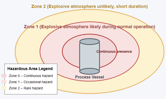
Hazardous area classification
Understanding Intrinsic Safety
IS is a protection concept for electrical circuits. The circuits are designed so they cannot release sufficient energy. The energy may be electrical or thermal. This prevents ignition of a hazardous atmosphere.
This condition must be met during normal operation. It must also be met under specified fault conditions. The key idea is energy limitation.
Voltage and current are controlled. Stored energy in inductors and capacitors is also controlled.
Even if a short circuit occurs, safety is maintained. Component failure can also occur. The energy available remains below the ignition threshold.
This applies to the surrounding atmosphere. Intrinsically safe devices are typically marked as “Ex i”.
They are further classified based on protection level. The most common levels are Ex ia and Ex ib. Ex ia equipment is safe with two independent faults. It is suitable for Zone 0. Ex ib equipment is safe with one fault. It is suitable for Zone 1.
The Ignition Triangle
To understand IS devices, one must look at the ignition triangle:
- Fuel: The flammable gas or dust in the environment.
- Oxygen: Present in the ambient air.
- Ignition Source: The heat or spark from an electrical device.
Intrinsically safe design removes the ignition source entirely. It ensures that any spark produced is too weak. The spark cannot ignite the fuel.
It also ensures that no surface overheats. The surface temperature remains below autoignition thresholds. This applies to surrounding gases.
Basic Principles of Intrinsic Safety
IS relies on fundamental electrical and thermal principles.
First, voltage and current must be limited.
This ensures that any spark has insufficient energy. The spark cannot ignite a flammable mixture.
Second, component temperatures must remain low. They must stay below the auto-ignition temperature.
This applies to the hazardous substance present. Capacitors and inductors receive special attention.
They can store energy. A charged capacitor can release energy suddenly during a fault. An inductor can generate high voltages.
This happens when the current is interrupted. Designers carefully limit component values. They may also use protective elements.
These measures control stored energy. Another principle is fault tolerance. Standards require circuits to remain safe.
This applies even if specific components fail. This requirement leads to conservative design margins.
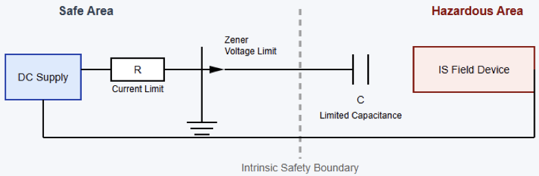
It also leads to redundant protection elements. The next figure illustrates a simplified IS circuit showing voltage and current limiting resistors. It also indicates Zener diodes and controlled capacitance.

Key Components in Intrinsically Safe Systems
An intrinsically safe system usually consists of three main parts. These parts are the field device. They also include the associated apparatus. Interconnecting wiring is the third part.
The field device is the instrument located in the hazardous area. Examples include a temperature sensor or a pressure transmitter.
A proximity switch may also be used. A handheld communicator is another example. This device is designed to operate with very low power.
The associated apparatus is typically located in a safe area. It may also be in a less hazardous zone.
Common examples include Zener barriers. Galvanic isolators are also common. These devices limit the energy transfer.
Energy flows from the safe area to the hazardous area. IS requirements must be complied with by the interconnecting wiring. Cable parameters such as capacitance are controlled. Inductance is also controlled.
These parameters contribute to stored energy. Cable length and type are often specified. This information appears in system documentation.
Zener Barriers and Galvanic Isolators
Zener barriers are widely used as an associated apparatus. They are common in intrinsically safe systems.
They use resistors and Zener diodes. These components clamp the voltage to a safe level. When the voltage exceeds a threshold, the diodes conduct.
Excess energy is diverted to the ground. Proper grounding is essential. It ensures Zener barriers function safely. Galvanic isolators also provide energy limitation. They offer electrical isolation as well.
This isolation is between safe and hazardous areas. They use transformers or optocouplers.
Capacitive coupling may also be used. These methods transmit signals without a direct connection. This approach improves noise immunity.
It eliminates the need for a high-integrity ground connection. Both methods are effective. The choice depends on system requirements. Grounding conditions must be considered. Cost considerations also influence the decision.
Design and Certification Standards
Intrinsic safety is governed by strict international standards. These standards ensure consistent protection. They also ensure reliable protection.
IEC 60079-11 is the most recognized standard that covers installation practices.
In North America, equivalent standards exist. They are published by ANSI, FM, and UL. Equipment must undergo rigorous testing.
Certification is performed by recognized bodies. This is required before use in hazardous areas.
Certification covers electrical parameters. It also covers fault conditions and temperature rise. Labeling is also included.
Each intrinsically safe device includes control drawings. These drawings specify allowable connections.
Cable parameters and associated apparatus are specified. Compliance with these standards is not optional.
Incorrect installation can invalidate intrinsic safety. Substitution of components can also invalidate safety. Such actions can create serious hazards.
Applications of Intrinsically Safe Devices
Intrinsically safe electrical devices are commonly used in measurement. They are also used in control and communication applications.
Typical examples include pressure transmitters. Temperature transmitters are also common.
These are used in oil and gas facilities. Other examples include level sensors. Flow meters are used in refineries.
Portable equipment also uses intrinsic safety frequently. Examples include gas detectors. Calibration tools are also used.
Handheld radios are common. These devices allow safe operation in hazardous areas. In modern industrial plants, intrinsically safe networks are used. They support digital communication protocols. This enables advanced diagnostics.
Remote monitoring is also enabled. Because intrinsic safety limits power, it suits low-energy devices. It is not suitable for large motors. High-power actuators are also unsuitable.
Advantages of Intrinsic Safety
One main advantage of intrinsic safety is its preventive nature. Instead of containing explosions, it eliminates the ignition possibility.
This approach significantly enhances personnel safety. Installation and maintenance are often simpler.
This is compared to explosion-proof equipment. Intrinsically safe circuits can be worked on while energized.
Proper procedures must be followed. This feature reduces downtime. It also improves operational efficiency.
Intrinsic safety allows lighter enclosures. Smaller enclosures are also possible. Flexible wiring methods can be used.
These benefits translate into lower installation costs. This is especially true for complex plants. Such plants have extensive sensor networks.
Limitations and Challenges
Despite its advantages, intrinsic safety has limitations. The most significant constraint is power. Because energy is intentionally limited, devices cannot drive high-power loads.
Motors usually require other protection methods. Heaters also require other methods. Large solenoids are included as well.
System design can be complex. Engineers must calculate loop parameters carefully. Cable characteristics must be considered, and compatibility must be ensured. This applies between field devices and associated apparatus.
Documentation must be followed precisely. Control drawings must also be followed. Cost can also be a factor. Certified intrinsically safe equipment may be expensive. Barriers may also be more expensive.
They often cost more than standard devices. However, these costs are often offset. Reduced installation complexity helps. Improved safety also offsets costs.
Comparison with Other Explosion Protection Methods
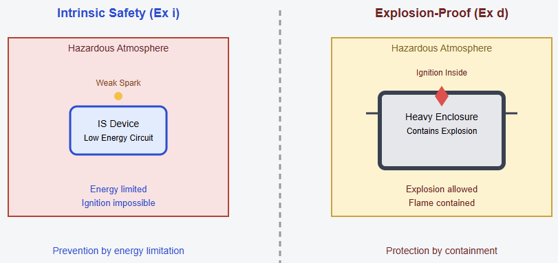
Intrinsic safety differs fundamentally from explosion-proof enclosures. It also differs from pressurization. Explosion-proof equipment allows ignition inside an enclosure.
The enclosure is robust. It prevents the flame from escaping. Pressurization keeps flammable atmospheres out. It does this by maintaining positive pressure.
In contrast, intrinsic safety prevents ignition by design. This makes it suitable for sensors. Communication devices also benefit.
In practice, industrial plants often use combinations. Multiple protection techniques are applied.
The most appropriate method is selected. This depends on equipment type. The diagram below shows a comparative illustration of intrinsic safety versus explosion-proof enclosure concepts.

Maintenance and Live Work
One of the greatest benefits of IS devices is live maintenance. Energy levels are very low. A technician can open a junction box safely. A sensor can be swapped without a shutdown. The entire plant remains operational.
This saves millions of dollars in downtime. The global energy sector benefits significantly. However, technicians must use certified IS tools. Tools must meet certification requirements. This avoids introducing high-energy sources.
Future Trends in Intrinsically Safe Technology
Advances in low-power electronics are expanding intrinsic safety. Wireless communication also contributes to this expansion.
Modern microcontrollers enable greater functionality. Energy-efficient sensors are also important.
Wireless protocols operate within strict power limits. Intrinsically safe wireless sensor networks are increasingly used. They support condition monitoring.
Predictive maintenance is also supported. Industrial Internet of Things applications are enabled.
These systems reduce cabling requirements. They maintain high safety standards. As digitalization continues, intrinsic safety will remain essential. It is a key enabling technology.
It supports safe industrial automation. Intelligent systems benefit from this approach. Hazardous environments remain protected.
Conclusion
Intrinsically safe electrical devices represent effective safety solutions. They are elegant solutions for hazardous areas.
Electrical and thermal energy are limited. Levels remain below ignition thresholds. This prevents explosions proactively.
Explosions are not controlled after occurring. This approach offers significant benefits. Personnel safety is improved.
System reliability is enhanced. Maintenance flexibility is increased. Intrinsic safety imposes power limitations.
Careful design and certification are required. Despite this, advantages remain clear. Intrinsic safety is indispensable for modern instrumentation.
Control systems rely on this protection. As industrial systems become smarter, maintaining safety is essential. Intrinsically safe devices combine innovation with uncompromising safety.
FAQ: Intrinsically Safe Electrical Devices
Definition of “intrinsically safe”?
Under normal or stated fault situations, it implies the electrical equipment and wiring are built to avoid releasing enough electrical or thermal energy to set a dangerous environment on fire.
In dangerous environments, why is intrinsic safety so vital?
Small sparks or hot surfaces in an explosive setting can lead to fires or explosions. Energy restriction lets IS stop ignition.
Does Intrinsic safety prevent explosions by means of its mechanism?
By restricting voltage, current, capacitance, and inductance so that any spark or heat generated is under the ignition energy of the gas or dust, there.
Which equipment uses intrinsic safety?
Certified for hazardous areas, low-power tools like transmitters, sensors, switches, and communication devices running on low energy