Automation projects require careful controller selection for success. Choosing incorrectly can increase costs and reduce reliability. Different processes demand different control strategies and architectures.
Engineers must evaluate performance, scalability, and integration requirements. Control objectives vary across industries and application types.
Some systems require simple logic-based decisions. Others demand advanced motion or process control.
Environmental conditions also influence controller hardware suitability. Budget constraints further affect feasible technology options. Safety standards may impose specific controller certifications.
Downtime and costly redesign are surely prevented by proper evaluation. This article studies controller types, selection criteria, and practical decision factors.
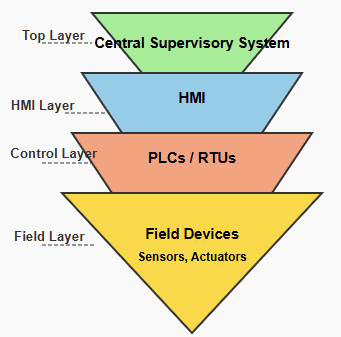
Understanding Control Requirements
Every automation project begins with defined control objectives. Clear objectives guide appropriate controller technology decisions.
Identify whether control is discrete or continuous. Discrete control handles on off logic operations.
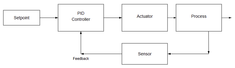
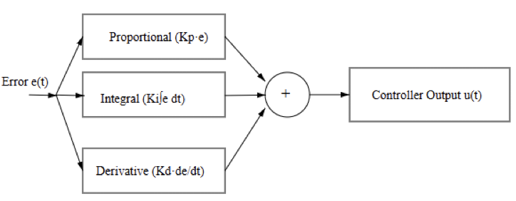
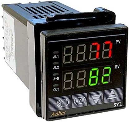
Continuous control manages variables like temperature and pressure. Motion control coordinates position, speed, and torque.
Batch processes require sequencing and timing coordination. Real-time response requirements must be clearly specified.
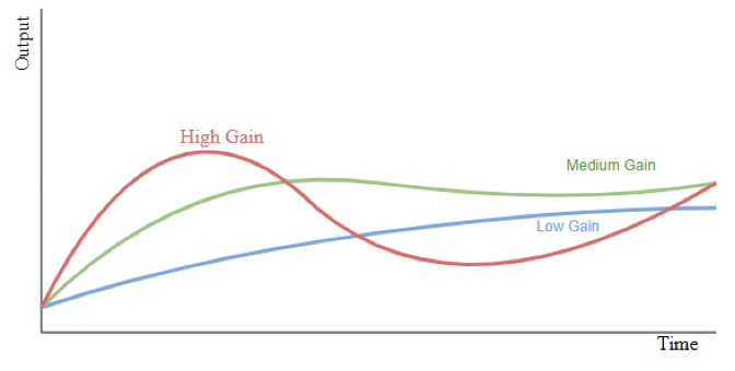
High-speed machines demand faster processing capabilities. Slower processes tolerate longer controller scan times.

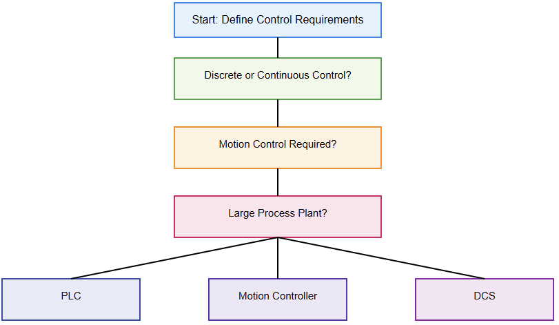
Decision Flowchart for Selecting an Automation Controller Type
Evaluating System Complexity
System complexity strongly influences controller type selection. Small machines may require limited input output capacity.
Large plants demand thousands of connected devices. Evaluate the number of sensors and actuators required.
Consider future expansion and modular upgrade possibilities. Complex systems benefit from scalable controller platforms.
Simple applications may use compact integrated controllers. Programming complexity also affects hardware performance requirements.
Advanced algorithms require greater memory and processing power. Complexity assessment prevents underpowered controller selection mistakes.
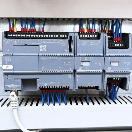
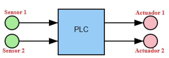
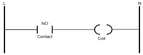
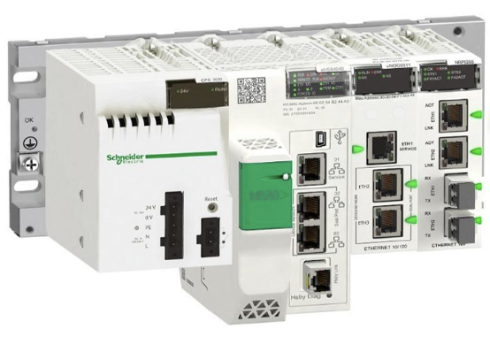
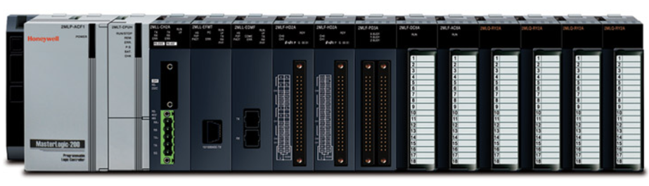
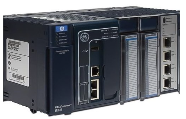
Programmable Logic Controllers
These are popularly known as PLCs; they do dominate industrial automation applications in all sectors.
PLCs excel in rugged industrial environments worldwide. They provide reliable, discrete, and sequential control.
Ladder logic programming simplifies maintenance and troubleshooting. Modular PLCs support expandable input output configurations. Communication modules enable networked distributed architectures.
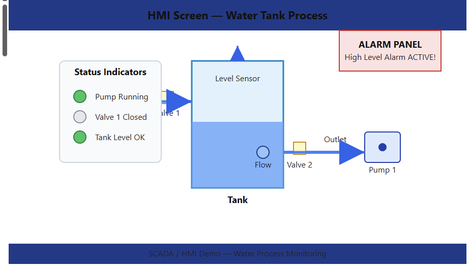
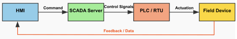
PLCs integrate easily with human-machine interfaces. They handle moderate motion and process tasks.
High-end PLCs offer advanced processing features. PLCs remain preferred for factory automation systems.
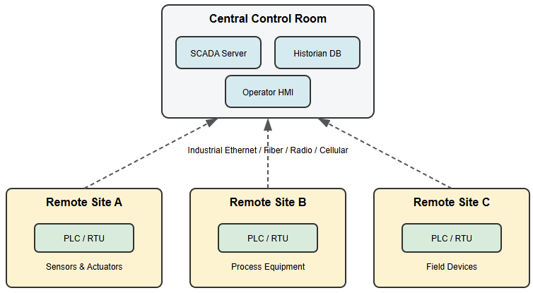
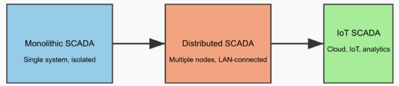
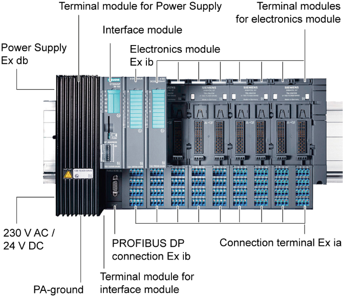
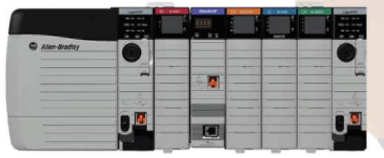
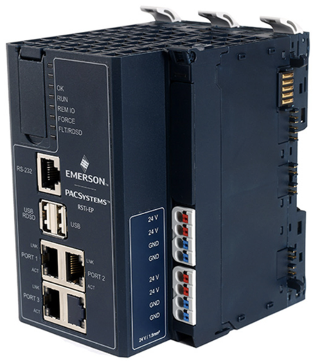
Distributed Control Systems
Distributed control systems suit large continuous processes. DCS platforms manage complex process industries effectively.
They provide centralized supervision with distributed controllers. Redundancy features enhance reliability and availability.
Process industries require precise analog control capabilities. DCS systems integrate advanced control strategies natively. Engineering tools support large-scale configuration management.
Lifecycle support remains strong for process facilities. DCS solutions involve higher initial investment costs. They suit refineries, power plants, and utilities.

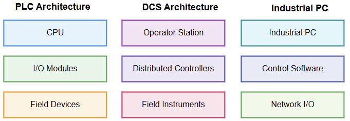
Structural Comparison of PLC, DCS, and Industrial PC Architectures
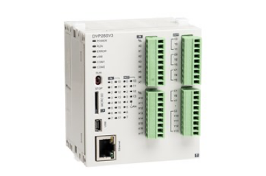
Industrial PCs and Soft Controllers
Industrial computers offer flexible control platform options. Soft controllers run automation software on PCs.
They support advanced data processing applications. Complex motion and robotics benefit from computing power.
Industrial PCs integrate vision and analytics functions. Open architecture allows customized software development.
Environmental protection must match industrial conditions. Maintenance requires information technology expertise.
Cybersecurity becomes critical in networked architectures. Industrial PCs suit data-intensive automation systems.
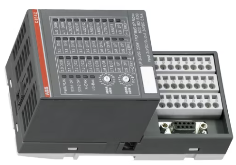
Microcontrollers and Embedded Systems
Embedded controllers serve compact, specialized automation devices. Microcontrollers provide cost-effective control solutions.
They integrate the processor, memory, and peripherals. Design flexibility supports customized hardware implementations.
Development requires deeper programming knowledge and testing. Embedded systems suit high-volume product manufacturing.
They offer low power consumption advantages. Real-time performance depends on firmware design.
Expansion capabilities remain limited compared to PLCs. Embedded options fit small dedicated machines.
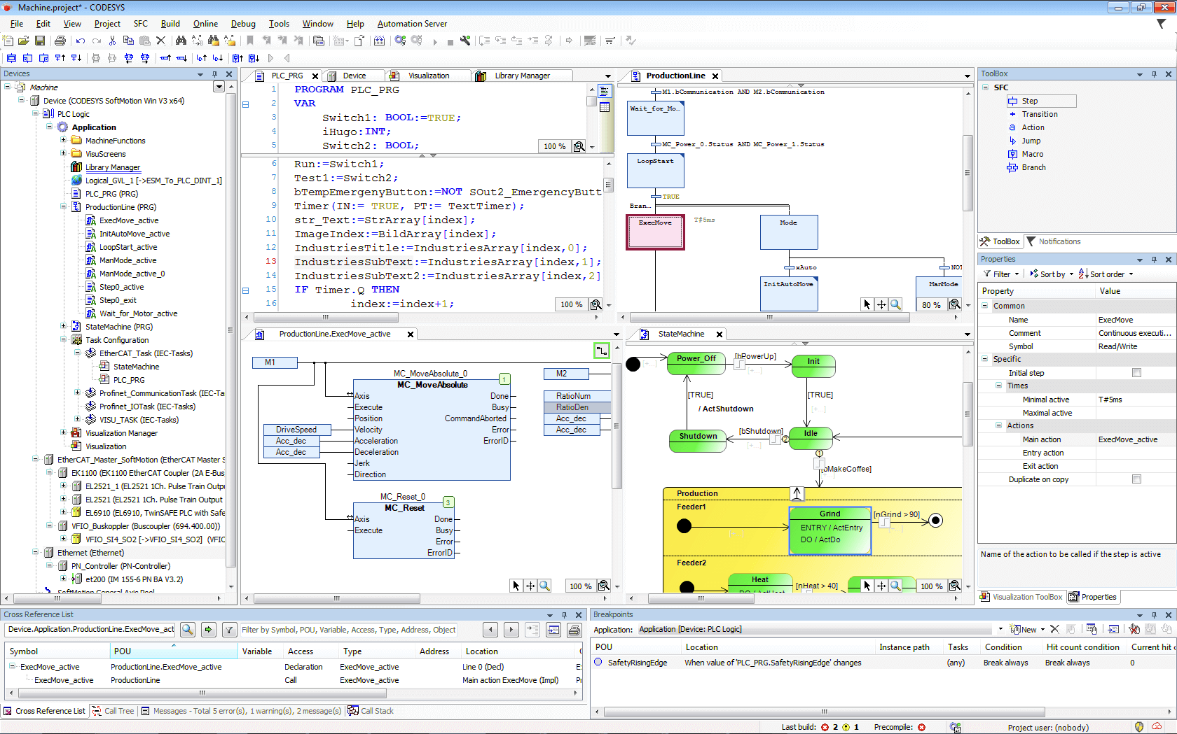
Motion Controllers
Motion control applications require specialized controller features. Precise positioning demands deterministic high-speed processing.
Multi-axis coordination requires synchronized control loops. Motion controllers manage servo and stepper drives.
Advanced interpolation supports complex trajectory generation. Packaging and robotics rely heavily on motion control.
Integration with safety systems remains essential. Communication latency affects motion performance significantly.
Some PLCs include integrated motion capabilities. Dedicated motion controllers suit demanding precision machines.
Safety Controllers
Safety requirements influence controller selection decisions. Certain applications require certified safety-rated controllers.
Safety PLCs meet international functional safety standards. They monitor emergency stops and protective devices.
Redundant architectures increase fault tolerance reliability. Programming environments support validated safety function blocks.
Integration with standard control simplifies system design. Certification reduces compliance documentation efforts significantly.
Safety controllers increase overall project investment costs. However, they ensure personnel and equipment protection.
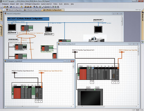
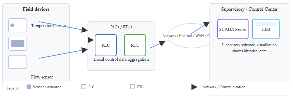
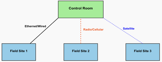
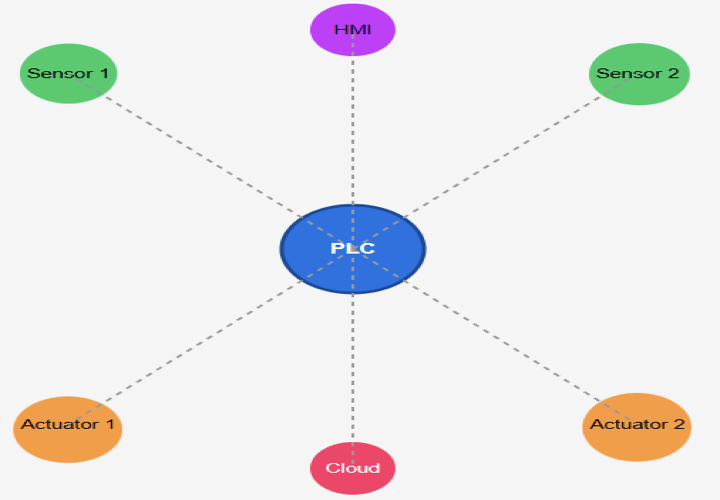
Communication and Networking Considerations
Modern automation depends on reliable communication networks. Controller compatibility with industrial protocols is essential.
Common protocols include Ethernet IP, and Modbus. Real-time networks support deterministic control performance.
Evaluate required data exchange rates carefully. Cloud connectivity may require advanced communication features. Cybersecurity protection must be considered during selection.
Network topology influences controller port requirements. Remote diagnostics require secure communication channels. Communication needs shape overall controller architecture decisions.
Environmental and Physical Constraints
In any industrial environment, challenging operating conditions are always present. Temperature extremes affect electronic component reliability. Vibration and shock require ruggedized hardware designs.
Dust and moisture demand appropriate enclosure ratings. Hazardous areas require explosion-proof certifications.
Panel space limitations influence controller form factor. Power supply availability affects hardware compatibility.
Cooling requirements impact cabinet design considerations. Environmental assessment prevents premature equipment failure. Physical constraints narrow suitable controller options.
Budget and Lifecycle Costs
Initial purchase price influences selection decisions. However, lifecycle costs require deeper evaluation.
Maintenance expenses vary across controller platforms. Spare part availability affects long-term sustainability. Vendor support quality influences downtime risks.
Training requirements add hidden project costs. Software licensing models impact operational budgets. Energy consumption contributes to total ownership costs.
Upgradability protects investment against technology obsolescence. Financial analysis ensures balanced controller investment decisions.

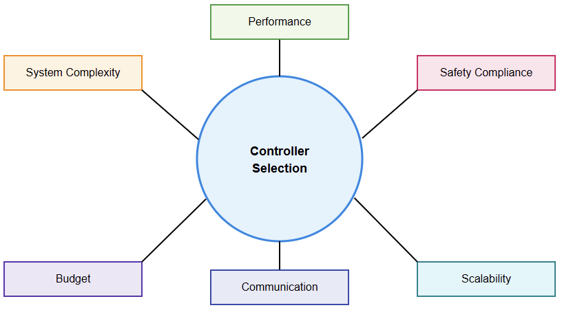
Key Technical and Factors (Operational) Influencing Controller Selection
Vendor Support and Ecosystem
Strong vendor ecosystems simplify integration tasks. Widely adopted platforms offer extensive documentation resources. Community knowledge accelerates troubleshooting and commissioning.
Availability of trained technicians reduces project risk. Local technical support improves service responsiveness.
Long-term product roadmaps protect investment confidence. Third-party modules expand system functionality.
Standardization across plants simplifies maintenance procedures. Proprietary platforms may limit future flexibility. Vendor evaluation remains critical for sustainable automation.
Future Scalability and Integration
Automation systems must accommodate future expansion needs. Select controllers supporting modular hardware growth.
Software scalability ensures additional feature integration. Data analytics integration may require open interfaces.
Industry four concepts demand connectivity readiness. Edge computing trends influence controller capabilities. Interoperability with existing equipment prevents replacement costs.
Standard communication protocols enhance long-term compatibility. Cloud integration may support predictive maintenance strategies. Future planning strengthens overall controller selection decisions.
Conclusion
This article highlighted controller types, evaluation criteria, and practical selection strategies.
Selecting the right controller requires systematic evaluation. Control objectives must align with hardware capabilities.
System complexity determines required processing performance. Environmental factors narrow feasible hardware options.
Budget analysis balances cost and long-term value. Communication requirements shape architectural decisions significantly. Safety considerations demand certified controller solutions.
Vendor support influences project sustainability outcomes. Scalability ensures adaptability to future demands.
Plus, if the careful selection is performed, it improves reliability and operational efficiency. Engineers benefit from structured decision-making approaches. Proper controller choice strengthens automation project success.
Frequently Asked Questions
What is the first step when selecting a controller?
The very first step is to segment your control requirements and objectives very well. You need to find out if the system will do discrete, continuous, or motion control, and also think of how the system will perform.
Why is understanding your current system important before choosing a controller?
Finding out if your system is new or existing will make sure that the hardware you decide to use will be compatible, and this will prevent you from running into integration problems, which, in the end, will save you time and money.
How do I/O requirements affect controller selection?
The choice of controller depends very much on the number and types of inputs and outputs the application will require, and this applies to both digital and analog devices; if a controller is equipped with a limited I/O capacity, it can be a limitation on system functions.
What role does the environment play in controller selection?
Conditions of the environment, such as temperature, humidity, presence of dust, and vibration, will make you consider whether the controller you choose should be one that is ruggedized or of industrial grade and able to withstand a harsh environment.
Do controllers differ in communication capabilities?
Yes, to be able to communicate effectively with other devices, especially when there are many devices in a network, or if there is integration to other systems, controllers must have the communication protocols (such as Ethernet/IP or Modbus) that are required.
What is the difference between PLC and DCS for automation?
PLCs are generally hardware simplified and optimized for discrete or modular machine controls that are more repetitive and determined, such as parts companions, while DCS are designed for the control of large continuous processes with complex analog control and distributed architecture needs.
How important is future scalability in selecting a controller?
Very important is selecting a platform that can be expanded with hardware or software features, allowing you to postpone the purchase of a new system and thus save money.
Should I consider training and support when choosing a controller?
Yes. Vendors with strong support, documentation, and training resources reduce project risks and improve long-term maintainability.
How do controller performance requirements influence the choice?
You should choose a controller with a higher processing power or CPU for working with high-speed machines and operations that require real-time, because these demands imply more utilization of the resources of the devices. A smaller, cheaper controller can be used for less complex applications.
Are safety requirements part of the selection process?
Definitely. To ensure the safety of people and equipment, it is necessary to use safety-rated controllers or architectures with redundancy for emergency shutdown and personnel protection systems.
Can I mix different controller types in one system?
Yes. To meet different parts of a system in the best possible ways, it is quite common that different types of controllers (PLC, PAC, DCS, etc.) are used together in many practical automation architectures.
Is cost the only factor that determines the right controller choice?
No. Cost definitely matters, but other aspects like maintenance, scalability, and performance in the long run are just as important when picking a sustainable controller.