In modern motion control systems, encoders play a critical role. This is because they provide precise feedback on direction, speed, and position. They are widely used in industrial automation, robotics, and CNC machines.
They are also essential in elevators and renewable energy systems. Generally, encoders convert mechanical motion into electrical signals. In this way, they enable controllers such as PLCs and drives to make accurate decisions.
They do the same to motion controllers. There is an existence of many encoder technologies available. But absolute encoders and incremental encoders are the most commonly used.
In general, both types serve the same fundamental purpose. They have significant differences in their operating principles. In addition, In their signal characteristics and application suitability.
It is important to select the right encoder for a specific system. So, engineers must understand these differences.
This article explains how absolute and incremental encoders work. It compares their features and examines typical applications for each.
Understanding an Encoder
An encoder is an electromechanical device that converts linear or rotary motion into electrical signals.
The signals convey information about direction, speed, and position. These signals are interpreted by control systems to monitor movement.
They can also be used to provide closed-loop feedback. Encoders are typically mounted on motor shafts and lead screws.
They can also be found in conveyor rollers or rotating machine elements. Encoders can be classified in several ways.
These ways could be rotary or linear, optical or magnetic, and contact or non-contact. However, there is another way of classification. This way is based on how position information is generated and retained.
This distinction leads to two main types, which are incremental encoders and absolute encoders.
The first one provides relative position information. The second one gives a unique position value at all times.
How do Incremental Encoders Work
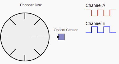
An incremental encoder generates a series of electrical pulses. This phenomenon can be caused by the shaft rotating or by moving linearly.
Each pulse corresponds to a small increment of movement. The controller determines position by counting these pulses.
The count should start from a known reference point. Most of the time, the reference is established during system startup or homing. Most incremental encoders produce two output signals. They are commonly called Channel A and Channel B.
These channels are offset by 90 electrical degrees. This quadrature arrangement allows the controller to determine the direction of rotation. It does so by comparing the phase relationship between the two signals.
Some incremental encoders also include a third signal, known as the index or Z channel. It provides a single pulse per revolution and is often used as a reference marker.

Characteristics of Incremental Encoders
Their simplicity and high resolution make incremental encoders widely used. The position is obtained through counting the number of pulses. Resolution is set by the number of pulses per revolution (PPR).
Higher PPR values allow for finer motion measurement. For this reason, incremental encoders are appropriate for high-precision speed and motion control.
Unlike absolute encoders, incremental encoders do not provide direct absolute position information.
The pulse count resets to zero once the power is lost. Plus, to re-establish the reference position, the system must then perform a homing routine.
Incremental encoders typically use simpler electronics. This results in lower cost and wider availability.
They are also capable of very high rotational speeds. For this reason, they are popular in motor feedback applications.
Applications of Incremental Encoders
Incremental encoders are widely used in applications where relative motion and speed measurement are the primary requirements.
Common examples include motor speed feedback and conveyor systems. Also, in packaging machines and basic CNC axis control.
They are particularly suitable for systems that perform a homing sequence at startup. Also, where the occasional loss of position data does not pose a significant risk.
They are so affordable and possess high performance. This makes them ideal for large-scale industrial installations where cost is a major factor.
How do Absolute Encoders Work
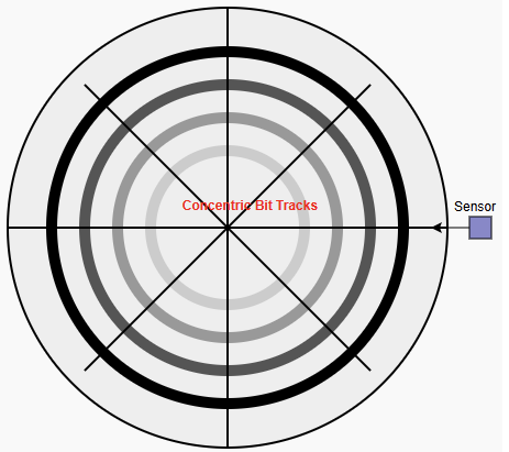
An absolute encoder provides a unique digital code for each shaft position. In this encoder, the output represents the actual position directly. Different from incremental encoders, which give changes in position.
This means that the position is known immediately when power is applied. Homing or referencing procedure is not required here. Absolute encoders achieve this by using a coded disk or magnetic pattern.
Each angular position corresponds to a distinct binary, gray code, or serial data value. The sensing elements read this code and transmit it to the controller. Absolute encoders can be categorized into single-turn or multi-turn.
In the first one, the position is tracked within one revolution. While in the second one, the number of full revolutions is also recorded

Characteristics of Absolute Encoders
The defining feature of absolute encoders is their ability to retain position information through power interruptions. The correct position is instantly reported as soon as the power is restored.
This capability is essential in vast applications. For instance, in those cases where unexpected movement or incorrect positioning could cause damage or safety hazards. Absolute encoders are often used in systems that require precise positioning without homing.
Common examples include robotic arms and wind turbine pitch control. They are also widely used in automated storage systems.
Multi-turn absolute encoders may use mechanical gearing to track revolutions. They can also rely on electronic counting with backup batteries.
In some designs, energy-harvesting technologies are used for this purpose. They are more complex sensing and signal processing. So, absolute encoders are generally more expensive than incremental encoders.
Serial protocols such as SSI, BiSS, CANopen, or EtherCAT can often be used to communicate. This simplifies the wiring process.
Applications of Absolute Encoders
In applications where position must always be known, absolute encoders are crucial. It does not matter even after a power failure.
These include cranes, elevators, and robotics. Without forgetting wind turbines and medical equipment.
They are also common in safety-critical systems. Because incorrect positioning could result in equipment damage or personal injury.
In such systems, the ability to know the exact position at all times significantly improves reliability and safety, but requires compatible controllers.
Comparison Between Incremental vs. Absolute
Incremental encoders typically output square-wave signals on multiple channels. These signals are processed by high-speed counters.
These counters may be in PLCs, drives, or motion controllers. The controller must continuously monitor the pulse stream to maintain accurate position information.
In contrast, absolute encoders output a digital word that directly represents position. The most general serial communication protocols or parallel form can be used to transmit the data.
Serial absolute encoders reduce the number of wires required. They also offer robust communication over longer distances.
Accuracy, Resolution, and Reliability
As mentioned above, resolution in incremental encoders is defined as PPR. In contrast, in absolute encoders, it is defined by the number of bits used to represent position.
For instance, 256 distinct positions per revolution are obtained from an 8-bit absolute encoder.
Nevertheless, for both encoder types, accuracy depends on mechanical alignment and sensor quality.
It also highly relies on signal processing. Actually, incremental encoders can achieve extremely high resolutions.
The main problem is their reliance on pulse counting. This makes them vulnerable to errors if pulses are missed due to noise or high speed.
Absolute encoders are inherently more reliable in environments where power interruptions or emergency stops are common. Since position is encoded directly, there is no cumulative error from missed pulses.
Cost and System Integration Considerations
When choosing between absolute and incremental encoders, cost must be considered. Incremental encoders are generally less expensive.
They are also easier to integrate into simple control systems. They require fewer specialized communication interfaces and are widely supported by standard PLC inputs.
Absolute encoders, while more costly, can reduce overall system complexity. Because of eliminating homing sensors, limit switches, and startup routines.
In complex automation systems, this reduction in auxiliary components can offset the higher initial cost of the encoder itself.
Conclusion
The present article details how absolute and incremental encoders work. It further compared their features and addressed typical applications for each.
Absolute and incremental encoders are essential in motion control and industrial automation.
However, they are designed for different requirements. Incremental encoders offer simplicity and high resolution.
Also, they are cost-effective. This makes them ideal for speed measurement and applications where homing is acceptable.
Absolute encoders, on the other hand, provide immediate and reliable position information.
This is offered even after power loss, which is critical for safety-sensitive and high-precision systems.
Selecting the right encoder requires careful consideration of system needs. It includes budget accuracy, startup behavior, and reliability.
Understanding the fundamental differences between absolute and incremental encoders is a must.
Because through it, engineers can design more robust motion control systems. Also, more efficient and reliable.
Frequently Asked Questions
What’s the main difference?
Absolute encoders provide a unique digital code for each shaft position, so the exact position is always known.
Incremental encoders generate pulses as the shaft moves, giving only relative position and direction.
What happens after a power loss?
Absolute encoders retain position information and report it immediately after power is restored.
Incremental encoders lose their count and require a homing routine to re-establish position.
Why do incremental encoders have A and B channels?
The A and B channels are quadrature signals offset by 90°, allowing the controller to detect both movement direction and speed. Some encoders also have a Z channel for a reference mark.
What output does an absolute encoder provide?
Absolute encoders output a digital code, often binary or Gray code, representing the exact position of the shaft. This can be transmitted via parallel lines or serial protocols like SSI, BiSS, or CANopen.
Is homing required at startup?
Absolute encoders do not require homing, as they inherently know the shaft position. Incremental encoders typically need a homing sequence or reference pulse after power-on.
Which type is more expensive?
Absolute encoders are generally more costly due to multiple bit tracks, sensors, and digital interfaces. Incremental encoders are simpler and usually less expensive.
Can incremental encoders give absolute position?
Not on their own. Absolute position can only be determined by homing, using an index pulse, or adding extra electronics.