Electrical systems often require controlled switching between different circuit paths. Single-pole double-throw switches satisfy this common electrical control requirement. They allow one input connection to alternate between two outputs.
This functionality makes SPDT devices widely useful in electrical applications. Engineers use SPDT switches for control, selection, and signal routing. Such switches appear in industrial panels, electronics, and automation systems.
If the operation SPDT is understood, this improves circuit design and troubleshooting accuracy.
The concept remains simple, yet applications range from basic to complex. A clear explanation helps learners grasp switching logic and practical usage. This article reviews the definition, construction, operation, and applications of SPDT.
What is SPDT?
SPDT stands for single-pole double-throw switching configuration. The term “single pole” refers to one common input terminal.
A double throw indicates two possible output connection terminals. Only one output connects to the input at any time.
SPDT switches alternate the common terminal between two throws. This configuration enables selection between two separate circuits.
SPDT devices can be manual, electromechanical, or electronic. They form a foundational concept in switching and control theory.
Understanding terminology prevents confusion with other switch types. SPDT functionality remains consistent across various physical implementations.
Basic Construction of SPDT Switch
One side of an SPDT switch is composed of one movable contact. The other side contains two fixed contacts.
The movable contact connects to the common pole terminal. Each fixed contact represents one throw connection path.
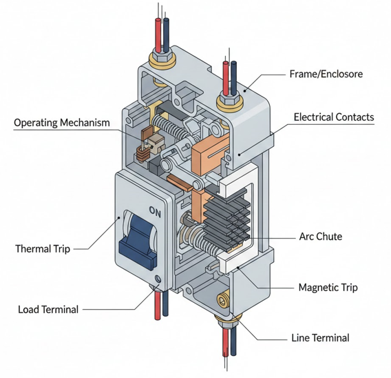
Mechanical actuation moves the movable contact between fixed contacts. The switch housing provides insulation and mechanical stability. Contact materials ensure reliable conduction and minimal resistance.
Springs provide contact pressure and stable switching action. The actuator may be a lever, button, or rotating knob.
Construction quality influences electrical performance and service life. Figure one can illustrate the basic SPDT internal contact arrangement. The following figure shows an SPDT.


Electrical Symbol of SPDT
Circuit diagrams represent SPDT switches using standardized electrical symbols. The symbol shows one common terminal connected to two alternatives.
A slanted line indicates the movable contact position. Only one throw connection appears closed at a time.
Symbols help engineers quickly identify switching functionality. Consistent representation avoids wiring and interpretation errors.
SPDT symbols remain similar across international standards organizations. They appear frequently in schematics for control circuits.
Learning symbols supports accurate reading of technical drawings. Figure two may show the SPDT symbol in schematic form.
Working Principle of SPDT
SPDT switches operate by redirecting current flow paths. Actuation moves the common contact between two output terminals.
Only one circuit path conducts electricity during operation. Switching action may be maintained or momentary, depending on the design.
Manual SPDT switches rely on physical user interaction. Relay-based SPDT switches use electromagnetic actuation principles.
Electronic SPDT functions may use semiconductor switching devices. The principle remains independent of voltage or current levels.
Reliable operation depends on proper contact alignment and force. This principle supports flexible control in electrical systems.
SPDT in Relay Applications
SPDT relays are widely used in industrial control systems. The relay coil energizes to change the contact connection state.
The deenergized state connects to a normally closed contact. An energized state connects to the normally open contact.
This arrangement enables automatic switching based on control signals. SPDT relays isolate control circuits from power circuits safely. They are essential for interlocking and logic implementation.
Relays provide electrical isolation and signal amplification benefits. Figure three can illustrate SPDT relay contact operation. SPDT relays remain fundamental components in automation panels.
SPDT Versus SPST
SPDT switches differ significantly from single-pole single-throw switches. SPST switches provide only simple on or off control.
SPDT switches provide selection between two output circuits. This difference increases functional flexibility significantly.
SPST designs require additional switches for similar control. SPDT designs reduce component count and wiring complexity.
Understanding this distinction aids proper switch selection. Both types share similar mechanical construction features.
Application requirements determine the appropriate switch choice. Figure four may compare SPDT and SPST symbols.
SPDT Versus DPDT
SPDT switches control one circuit path at a time. DPDT switches control two independent circuit paths simultaneously.
DPDT effectively combines two SPDT mechanisms mechanically. SPDT suits simpler control requirements and lower complexity.
DPDT suits reversing motors or polarity switching applications. Physical size and cost differ between these configurations.
Selection depends on the required switching complexity and isolation. Understanding differences prevents incorrect component specification.
SPDT remains more common for basic control tasks. Figure five can illustrate SPDT versus DPDT configurations.
Applications of SPDT Switches
SPDT switches are used in signal routing applications. They select between power sources or signal paths.
Audio systems use SPDT switches for channel selection. Control panels use them for mode selection functions.
Instrumentation uses SPDT switches for measurement range selection. Lighting circuits use SPDT switches for alternate control points.
Battery-powered systems use SPDT for power source switching. Automotive systems use SPDT switches for control logic.
Their versatility supports both low and high-power circuits. SPDT switches remain widely applied across many industries.
SPDT in Logic and Control Circuits
SPDT switches implement basic logic control functions. They can perform selection, inversion, or routing operations.
Control circuits use SPDT for manual override selection. They support fail-safe designs using default contact positions.
SPDT relays implement logical decisions in ladder diagrams. Their behavior aligns with Boolean logic switching concepts.
This makes SPDT valuable in educational control experiments. Logic reliability depends on proper wiring and contact rating.
SPDT elements remain relevant despite programmable controller usage. They provide simple hardware-based decision-making capability.

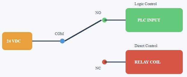
SPDT in the control circuit
Advantages of SPDT Switches
SPDT switches offer increased flexibility compared to simpler switches. They reduce wiring complexity in many control applications.
One device replaces multiple simpler switching components. They support both manual and automatic control methods.
SPDT switches are available in many voltage ratings. They support AC and DC electrical applications.
Their operation remains intuitive and easy to understand. Wide availability makes them cost-effective solutions.
They integrate easily into existing electrical designs. SPDT switches provide reliable long-term performance.
Limitations of SPDT Switches
SPDT switches inherently lack overload protection mechanisms. They cannot switch multiple poles simultaneously alone. Mechanical wear may affect long-term reliability. Contact arcing can occur under high load conditions.
Proper rating selection is necessary to prevent damage. They require careful wiring to avoid incorrect connections.
Electronic alternatives may offer faster switching speeds. As mentioned before, inherent overload protection features are a big issue for SPDTs.
Environmental conditions can influence performance and lifespan. Limitations must be considered during system design.
Conclusion
This article details the meaning, working principles, comparisons, and uses of SPDT.
SPDT switches represent an essential concept in electrical switching. They allow controlled selection between two circuit paths.
Understanding SPDT improves design accuracy and troubleshooting effectiveness. Construction, symbols, and principles were clearly explained.
Comparisons highlighted differences from other common switch types. Applications demonstrated versatility across many industries. Advantages and limitations were identified for informed selection.
SPDT remains relevant in modern electrical and control systems. Strong fundamentals support safe and efficient implementation.
If an SPDT concept is well acquired, engineers, technicians, and students will benefit greatly.
Frequently Asked Questions
SPDT stands for what?
Single Pole Double Throw is one input that can be linked to two potential outputs.
How does an SPDT switch work?
A commonly open (NO) or commonly closed (NC) terminal of the COM can route current to various circuits.
An SPDT switch has how many terminals?
You’ll usually find three terminals on an SPDT switch: one common, one NO, and one NC
Where are SPDT switches applied?
Like toggling signals or choosing modes, these are employed in circuits requiring a choice between two output routes.
How do SPST and SPDT vary?
SPDT gives you two output options to choose from; SPST just acts like a basic on/off switch.