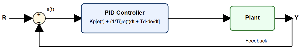
This is one of the very important terminologies in modern industrial automation. A PID controller is a control algorithm used to maintain a process variable, such as temperature, flow, pressure, or speed, at a desired setpoint.
A PID controller usually acts on the error signal. This means it continually measures the difference between the setpoint and the actual value (process variable).
It then adjusts the output to minimize that difference (error). They have the ability to adapt so easily to different processes.
This article is going to give a precise idea about of the PID controller. It explains the history, structure, types, working principle and the different type. It will also address the tuning methods, platforms advantages, and applications
What is a PID Controller?
The term PID stands for proportional integral derivative. It is a control algorithm (action) or mechanism used to control different process variables (PVs). The common PVs in industrial automation are pressure, flow, temperature and speed.
They work by measuring this feedback over time and adjusting the process’s input as needed to achieve a desired setpoint.
They are extremely popular in industrial settings and used to control, among other things, blowers, boilers, robotic arms and heaters. They can also be found in everyday applications, such as cruise control systems in cars.
Background (History)
In the year 1911, the first PID controller was developed by Elmer Sperry. Later on, Taylor Instrumental Company (TIC), the original name for a company founded in 185.
This company became a leading producer of control instruments. They implemented a former pneumatic controller with complete tunability in the year 1933.
The history of PID controllers goes back to early mechanical feedback systems. This was as early as in the 18th century. Instead, the first full PID controller was developed by Elmer Sperry for automated ship steering in 1911.
Then Nicolas Minorsky introduced the theoretical foundation in 1922, publishing the first mathematical analysis.
In the 1930s and 1940s, pneumatic versions were established. In addition, with the inauguration of Ziegler-Nichols tuning rules in 1942 .
They became practical for industrial use, became very useful and were widely adopted by the mid-1950s.
PID Controller Structure
Some manufacturers of PID controllers may arrange P, I, and D modes into one of three forms. These arrangements are known as the Interactive, Noninteractive, and Parallel.
So, in some cases, controller manufacturers allow a user to choose between these configuration options in the controller software.

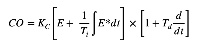
Interactive
The oldest arrangement of the P, I, and control modes is called the Interactive, Real, or Series form. The original pneumatic and electronic controllers had this form and is still found it in some controllers today.
In fact, the Ziegler-Nichols PID tuning rules were developed for this form. The mathematical presentation of interactive form can be presented as

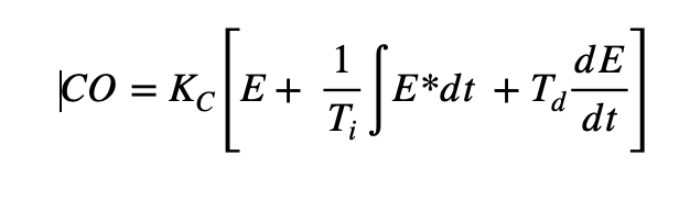
Noninteractive
The Noninteractive form is sometimes called the Standard, ISA algorithm or Ideal. Tuning rules such as the Cohen-Coon and Labda were designed for this form.
Notice that, if no derivative term is used (i.e. Td=0, ) the interactive and noninteractive are similar.
Mathematically, the noninteractive form can be shown as

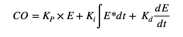
Parallel
Many academic textbooks discuss only the parallel form of PID, and don’t review the other forms. Most of the DCs also use the parallel form. This algorithm is simple to understand but not intuitive to tune.
The reason is that it does not contain a controller gain that would normally affect all three modes. Instead, it has a proportional that affects only the P-mode. This means regulating P-gain should be supplemented by adjusting the I and D simultaneously.
In mathematical form of the parallel form is indicated below

Working Principle
The main disadvantage of using of a low-cost simple ON/OFF controller is that only two control states are possible. These are states are fully ON or fully OFF that is why is used for a limited control application.
The simple ones, where these two control states are enough for the control objectives. However oscillating nature of this control limits its usage and hence it is being replaced by PID controllers.
PID controller maintains the output such that there is zero error between the process variable and setpoint. This is the desired achievement of any closed-loop operations. PID uses three basic control behaviors as explained below
- P – Action: Proportional or P- controller gives an output that is proportional to current error. It compares the desired or set point with the actual value or feedback process value. The resulting error is multiplied with a proportional constant to get the output. If the error value is close to zero, then this controller output is zero.
- I – Action: P-controller has a limitation, where there always exists an offset between the process variable and setpoint. This off-set is known as a steady-state error. Hence, I-controller is needed to provide necessary action to eliminate the steady-state error. It integrates the error over a period of time until the error value reaches zero.
- D-Controller: Although the I-controller is capable of bringing the steady-state error to zero. It lacks ability to predict the future behavior of the error. It reacts normally once the setpoint is changed. D-controller overcomes this problem by anticipating the future behavior of the error. Its output depends on the rate of change of error with respect to time. This is then multiplied by the derivative constant to give the kick-start for the output, thereby increasing system response.
Types of PID Controller
PID controllers can be classified into three types, such as ON/OFF, proportional, and standard-type controllers. Nevertheless, variations like PI and PD also exist. These controllers are used based on control objectives to be reached.
- ON/OFF Controller: The simplest type, it provides a binary output that is either fully on or fully.
- Proportional (P) Controller: This controller reduces cycling by adjusting the output proportionally to the error.
- Proportional-Integral (PI) Controller: This controller is essential for systems where zero steady-state error, is to be achieved.
- Proportional-Derivative (PD) Controller: This uses proportional and derivative terms to control the system, when integral action is not necessary.
- Proportional-Integral-Derivative (PID) Controller: This is the most thorough type because it uses all three control actions. The proportional term responds to the present error, and the integral term eliminates past errors. Plus, the derivative term anticipates future errors based on the current rate of change.
PID Controller Tuning
Control tuning, is the process of adjusting a control system’s parameters. This is done in order to achieve desired performance, including stability and responsiveness. Likewise, the PID controller must be tuned to suit the dynamics of the process to be controlled.
Manufacturers give the default values for P, I, and D terms. These values couldn’t give the desired performance and sometimes lead to instability and slow control performances. Now days, most of the control devices have capability of auto-tune.
However, different types of tuning methods are developed. They require much attention from the operator to select the best values of P, I, and d gains. Some of these are given below.
Trial and Error Method
This is the simplest method of PID controller tuning. In this method, we initially set Ki and Kd values to zero. In addition, we increase the proportional term (Kp) until the system reaches oscillating behavior.
Once in oscillation state, Ki is adjusted so that oscillations stop. Finally, regulate the D-term to get a fast response.
Process Reaction Curve Technique
This is an open-loop tuning technique used to produce a response when a step input is applied to the system. At first, control output must be manually applied to the system, proceeding to record the response curve.
Furthermore, the process relies on calculating dead time, the rise time of the curve, and slope. Finally, the obtained values are introduced to P, I, and D equations to get the gain values of PID terms.
Zeigler–Nichol’s method
Zeigler and Nichols introduced closed-loop techniques for tuning a PID controller. These include the continuous cycling method and the damped oscillation method. The steps for both approaches are identical, but the system’s oscillation response differs.
In this procedure, the proportional gain Kp is set to a chosen value while Ki and Kd remain at zero. The proportional gain is then gradually increased until the system begins to oscillate. These oscillations reach a steady and constant amplitude.
The gain at which these sustained oscillations occur is known as the ultimate gain (Ku). The oscillation period is called the ultimate period (Pc). After identifying Ku and Pc, the appropriate P, I, and D settings can be applied to the PID controller.
This is done by us using the Zeigler–Nichols tuning table (below), depending on whether a P, PI, or PID controller is being configured.

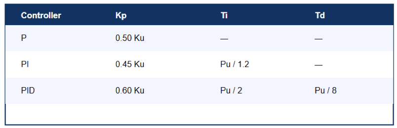
Zeigler–Nichols tuning table
Applications of PID Controllers
The PID controller applications include the following.
Temperature Control of Furnace
PID controller can precisely manages a furnace temperature by continuously calculating and minimizing the error. This error must be between the desired temperature (setpoint) and the actual measured temperature within the furnace.
PID is suitable in temperature control of a furnace because:
- Precision: Its capability of maintaining the temperature very close to the setpoint. This is critical for applications like material curing or metal heat treatment where specific thermal profiles (ramp and soak sequences) are required.
- Stability: Ability to prevent large temperature swings (overshoot and undershoot) comparing to the use of a local ON/OFF controllers.
- Automation: Most modern PID controllers feature an autotune function that automatically calculates the optimal P, I, and D terms. So, once properly tuned, it operates automatically without manual intervention This helps to reduce the risk of human error.
MPPT Charge Controller
The V-I characteristic of a photovoltaic cell mainly depends on the range of temperature as well as irradiance. Based on the weather conditions, the current and operating voltage will change constantly.
So, it is extremely significant to track the highest Power-Point for an efficient photovoltaic system. PID controller is used to finding MPPT by giving fixed voltage and current points to the PID controller.
Once the weather condition is changed then the tracker maintains current and voltage stable.
The Converter of Power Electronics
Converters are widely used in power electronics, such as in VFD applications. To achieve this, controllers such as PID are often applied. When a converter is connected to a system, any changes in load causes the converter’s output to vary.
For instance, when an inverter is connected to the load, high current will be drawn if the load increases. Thus, the current and voltage parameters tend to be unstable. In this case, this controller must generate adequate PWM signals. These signals will be employed to activate the IGBTs switches of the inverter.
Based on the change within the load, the response signal is provided to the PID controller so that it will produce the error. These signals are generated by relying on the of the error. Hence, this mechanism provides the changeable input and output through a similar inverter.
Why Use PID Controllers?
This chapter reviews some pros and cons of using PID controllers
Advantages
- P-part is proportional to the error, so it stabilizes the gain but produces a constant steady-state error.
- I-P is used to reduce and if possible, to eliminate the steady-state error.
- D Controller reduces the rate of change of error.
- As the PID controller works in three modes, error minimizing and data validation are easily possible.
- PID controllers offer a very high-efficiency steady-state controlled-variable (process-variable) than the normal on/off controllers.
Disadvantages
- The complexity of some PID controlling systems during the designing process. They also expensive comparing to the traditional ON/OFF controllers.
- Tuning methodology is another drawback of the PID controllers.
Key Takeaways: What is a PID Controller?
This article discussed an overview of the PID controller which includes history, structure, types, working principle and the different type. It also addressed tuning methods, platforms advantages, and applications.
So, from the above, we can dare to say that PID controller is a powerful tool. It is one of the back-bones to industrial automation.
As mentioned above, the power of this controller comes from the combination of modes. These modes are modes are proportional, integral and derivative.
The P-term gives response which proportional to errors. While the I-term eliminates and the D-term are for persistent steady-state errors and anticipates future errors, respectively. Together they provide accurately and stable control.
Finally, the PID controller is the sophisticated option when comes to solving complex control challenges efficiently.
The fact that the PID is still widely used shows how good it is. It will keep being a major part of control engineering especially in industrial automation.
FAQ: What is a PID Controller?
What does PID stand for in a PID controller?
PID stands for Proportional, Integral, and Derivative, representing the three control actions used in these types of controllers.
Can you briefly explain the function of a PID controller?
A PID controller is used in control systems to continuously adjust the output based on the error between the desired setpoint and the measured process variable.
It does this using three terms: proportional, integral, and derivative, each responding to present, accumulated past, and future trend of error, respectively.
What is the role of the Proportional component in a PID controller?
The Proportional component provides an output value that is proportional to the current error value. The proportional response can be adjusted by a factor known as the proportional gain.
Can you explain the Integral component of a PID controller?
The Integral component accounts for past values of the error and integrates them over time to produce the I output. This helps eliminate the residual steady-state error that occurs with a P-only controller.
What does the Derivative component do in a PID controller?
The Derivative component predicts the future trend of the error, based on its current rate of change. It helps in reducing the overshoot and settling time.
Why is tuning important in a PID controller?
Tuning a PID controller is crucial to ensure stability, minimize overshoot, and provide a fast response.
It involves adjusting the proportional, integral, and derivative gains to achieve the desired performance.
