Electric motors drive most industrial processes across modern facilities worldwide. They can support production, transport, pumping, and ventilation systems.
Their starting behavior significantly influences electrical stability and mechanical reliability throughout the installation.
Engineers must carefully choose appropriate motor starting methods to prevent unnecessary stress and operational disruptions.
Incorrect selection may cause voltage drops, excessive torque shocks, or premature equipment wear.
Two widely applied solutions are soft starters and variable frequency drives in modern industry.
Although both technologies manage motor startup, their objectives and capabilities differ substantially.
Many professionals assume a variable frequency drive always represents the superior technical solution.
However, this assumption often leads to unnecessary complexity and increased project cost.
A clear understanding of operational requirements ensures rational and economical equipment selection.
This article highlights the operating principles and practical criteria for selecting soft starters instead of variable-frequency drives.
What is a soft starter?
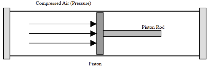
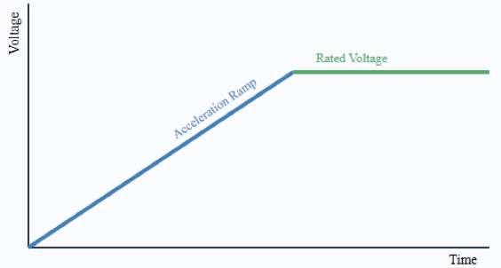
A soft starter is an electronic device designed specifically to control motor acceleration during startup.
It gradually increases the voltage applied to the motor terminals using controlled semiconductor switching devices.
By reducing the initial applied voltage, the motor draws lower inrush current from the electrical network.
This controlled current ramp significantly minimizes voltage dips affecting other connected equipment.
Reduced electrical stress improves the stability of transformers, generators, and upstream distribution components.
Soft starters commonly employ silicon-controlled rectifiers arranged in antiparallel configurations for each phase.
By adjusting the firing angle of these devices, the effective RMS voltage increases smoothly.
Once the motor reaches near rated speed, an internal bypass contactor typically engages.
This bypass action reduces thermal losses and improves the long-term efficiency of the equipment.
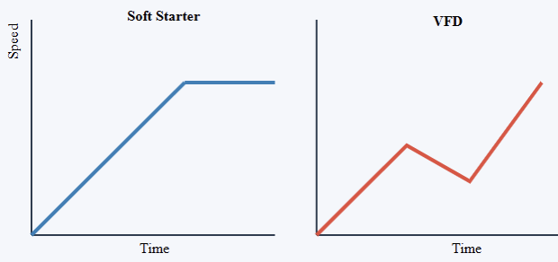
Importantly, a soft starter does not modify frequency during steady-state motor operation.
After startup completion, the motor operates directly at line frequency and rated speed. The primary objective remains limiting mechanical shock and electrical stress during acceleration and stopping.
Mechanical systems particularly benefit from the smooth torque buildup provided by soft starters.
Gearboxes and couplings experience significantly lower dynamic stress during motor engagement. This situation is also common in belts and shafts.
Gradual acceleration in pumping systems lowers hydraulic transients and lessens water-hammer effects. Installation complexity is still quite low relative to more sophisticated drive systems.
Usually, ramp time, initial voltage, and protection thresholds are set in parameter settings. For fixed-speed processes, this level of control often proves entirely sufficient.

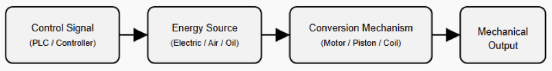
How a Variable Frequency Drive Operates
A variable frequency drive, often abbreviated as VFD, provides comprehensive control of motor speed and torque. Internally, it first rectifies incoming alternating current into a direct current link stage.
An inverter section then reconstructs alternating current at a variable frequency and voltage.
Because motor speed is proportional to supply frequency, changing frequency enables precise speed regulation.
Voltage modulation occurs simultaneously to maintain appropriate magnetic flux within the motor.
This coordinated control allows smooth acceleration. It also permits effortless deceleration and continuous speed adjustment.
VFDs continuously manage motor performance during the entire operation. This is not the case when soft taters are used.
They can implement programmable acceleration ramps, braking profiles, and torque limits.
Many modern drives incorporate communication interfaces for integration with industrial automation networks.
Advanced features may include internal PID controllers, diagnostics, and energy monitoring capabilities.
However, the switching nature of inverters introduces harmonic distortion into the electrical system.
Additional filtering or line reactors may therefore be required for compliance with standards.
Installation typically demands careful attention to proper grounding considerations. This also applies to appropriate shielding and cable length. Initial investment cost is usually higher compared with soft starter solutions.

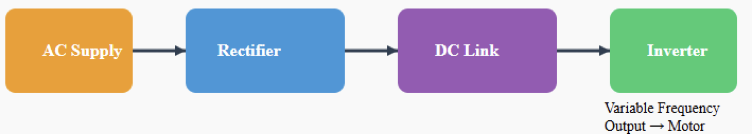
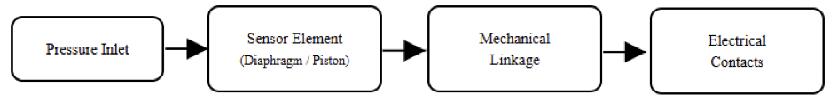
Basic Functional Blocks of a Variable Frequency Drive
Fundamental Differences Between the Two Technologies
The essential distinction between a soft starter and a VFD lies in speed control capability. A soft starter only manages voltage during startup and stopping sequences. A VFD continuously regulates frequency and voltage during steady-state operation.
Consequently, soft starters do not provide energy savings in constant torque processes. In contrast, VFDs can significantly reduce energy consumption in variable torque loads such as pumps and fans.
From a system perspective, soft starters generate minimal harmonic distortion during operation.
VFD installations may require harmonic studies and mitigation measures in sensitive networks.
Commissioning complexity also differs considerably between the two solutions. Soft starters generally require fewer parameters and shorter setup procedures.
VFDs demand more detailed configuration, especially when advanced control features are utilized.
Maintenance skill requirements often increase with drive complexity. Therefore, technology selection must align carefully with actual process needs. It should not be based solely on perceived sophistication.

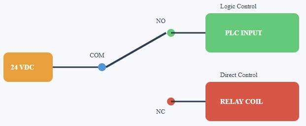
Soft Starter vs VFD: Operational Control Comparison
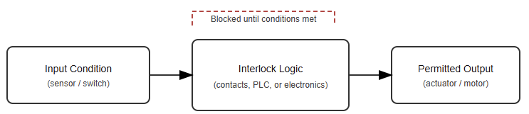
When to Use a Soft Starter Instead of a VFD
Soft starters are particularly appropriate for applications operating at constant rated speed. Conveyors transporting materials at fixed throughput represent a common example.
Centrifugal pumps running continuously at nominal flow without modulation also qualify. Large fans designed for steady ventilation loads similarly benefit from soft-starting methods. In these situations, speed variation does not provide meaningful process advantages.
High inertia loads often require controlled acceleration to prevent mechanical damage. Soft starters limit torque shocks and reduce stress on couplings and transmission components.
Electrical systems supplied by generators or weak grids benefit from reduced starting current.
Lower inrush current prevents excessive voltage drops affecting other critical loads. Water distribution systems experience fewer hydraulic transients when pumps start gradually.
Budget-constrained projects frequently favor soft starters due to lower capital cost. Facilities with limited technical support also appreciate their simpler architecture.
When operational flexibility is unnecessary, adding a VFD introduces avoidable complexity.
Situations Where a VFD Is More Suitable
Despite their advantages, soft starters cannot replace VFDs in dynamic process environments.
Applications requiring variable flow control depend on continuous speed adjustment capabilities.
HVAC systems achieve significant energy savings by modulating pump speeds. This also applies to fan speed.
Conveyor lines with changing production rates require flexible speed control. Processes demanding precise torque regulation at low speeds necessitate inverter technology. Regenerative braking or advanced motion control functions further justify VFD implementation.
In these contexts, the higher investment cost becomes economically defensible. Improvements in energy efficiency and better process control balance initial expenditures over time.
Advanced monitoring and predictive maintenance techniques also depend on integration with automation systems. Engineers, therefore, have to assess lifecycle advantages rather than just the buy price.
Practical Engineering Considerations
Correct equipment selection requires thorough analysis of load characteristics and operational objectives.
Motor insulation class and compatibility must be verified, particularly for inverter applications.
Cable lengths and electromagnetic compatibility considerations become critical in VFD installations.
Protection coordination must match the fault levels present in the distribution system. Environmental conditions such as dust and humidity influence enclosure selection. Also, ambient temperature impacts the aforementioned selection.
Correct equipment selection requires thorough analysis of load characteristics and operational objectives. Motor insulation class and compatibility must be verified, particularly for inverter applications.
Cable lengths and electromagnetic compatibility considerations become critical in VFD installations.
Protection coordination should align with available fault levels within the distribution system.
Environmental conditions such as dust, humidity, and ambient temperature influence enclosure selection.
Proper commissioning procedures ensure ramp times and protection parameters match application requirements. Oversizing equipment unnecessarily increases capital cost without technical benefit.
Under-sizing introduces overheating risks and potential operational instability. A balanced engineering approach evaluates performance, reliability, and economic constraints simultaneously.
Conclusion
This article introduced the functional distinctions and selection criteria for soft starters and variable frequency drives in industrial systems.
Soft starters provide controlled acceleration that reduces electrical and mechanical stress during motor startup.
They offer cost-effective solutions for constant speed applications without sacrificing reliability.
Variable frequency drives deliver continuous speed control, advanced functionality, and potential energy savings.
Their flexibility makes them indispensable in processes requiring dynamic adjustment and optimization.
Choosing between the two technologies depends on load behavior and performance objectives. Also, it relies on the infrastructure limitations of a certain project.
Avoiding unnecessary complexity improves long-term reliability and reduces lifecycle cost. Careful engineering evaluation ensures that each motor application receives the most appropriate and efficient solution.
FAQs: What is a soft starter?
Describe a soft starter
By slowly raising the voltage during starting, a soft starter is a device lowering motor inrush current.
Soft starters diverge from VFDs in their operational characteristics
While a VFD controls frequency and voltage for whole speed control, a soft starter only controls start-up voltage.
When should you install a soft starter?
Use a soft starter for applications with a fixed speed wherein smooth starts and lower electrical stress are most important.
When should a VFD be preferred?
When variable speed control, energy savings, or sophisticated motor control is needed, pick a VFD.
Do soft starters use power during operation?
No, soft starters cut current only at startup and do not provide continuous energy savings like VFDs.
Are VFDs more expensive and less complicated than soft starters?
Yes, VFDs often have less intricacy and lower initial cost than soft starters.