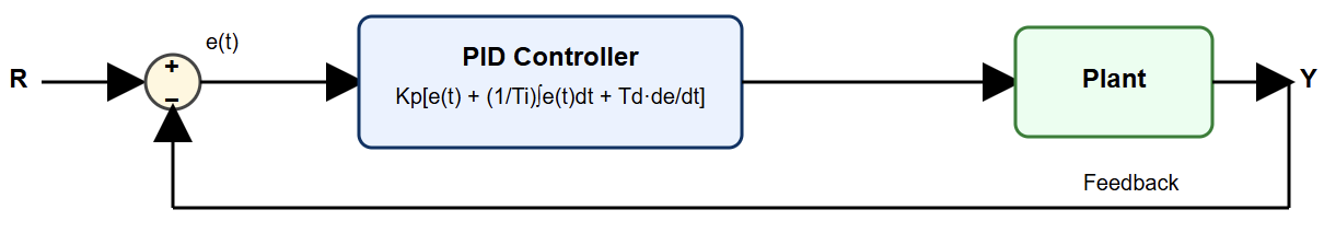
The Proportional–Integral–Derivative (PID) controller is important for industrial automation.
Apart from PID, there is the existence of more advanced control methods like model-based and adaptive controllers.
Nevertheless, PID loops are the most used controller in industrial processes globally. Their ability to regulate diverse systems, robustness and simplicity are what make them remain relevant.
Temperature, flow, speed, pressure, and level are just a few of the processes that can be controlled by the PID. To successfully explore the advantages of a PID controller, then good tuning is a must.
When a tuning process was incorrect, this could bring negative consequences. Some of these negative results are inefficient energy use, unnecessary wear on actuators, oscillations and process instability.
In contrast, properly tuned control loops provide quick stability, desired response times, minimal overshoot, and peak performance.
This article explores best practices for tuning PID loops. Furthermore, it combines engineering theory, real-world industrial knowledge, and proven field methods.
Understand the Process Before Tuning
It is important to know which kind of process is going to be controlled, because every loop behaves differently.
A flow loop changes immediately; instability may be present in chemical reaction, while a long delay is the characteristic of a temperature loop; a level tank might integrate endlessly.
This means that the process (tank) behaves as if it contains its own integral term. So, without understanding these dynamics first, even if the perfect tuning is achieved, this will be useless.
Hereunder we briefly explain things to take into account before starting the tuning process:
- Time constant: It is important to know once it reacts, how quickly the output reaches 63.2% of its final value.
- Dead time: The time it takes something to change after changing the output?
- Process gain: Check the sensitivity of the system?
- Disturbances: Their magnitude; How often they appear; Are hey periodically?
- Noise: How clean or noisy are our signals of interest?
- Equipment nonlinearity: Make actuators such as valves free of stiction or backlash.
It is recommended to spend a few minutes to study the process and understand it. This will help to save hours of trial and error.

Ensure the System is Safe and Stable Before Tuning
Make sure the process to be controlled works pretty well, safe and stably. This one sounds obvious, but most of the time tuning sessions fail because something in the system is broken or misconfigured.
As good practice, it is recommended that before starting the tuning process, you double-check:
- No mechanical sticking, deadband, or friction.
- Valves or actuators are free of stiction.
- The sensor is calibrated accordingly.
- The loop direction (direct or reverse) is correct.
- There are no remaining faults, no triggered alarms, or unstable process conditions.
Diving into tuning a loop with faulty equipment is like trying to fix your car alignment when the tire is flat. This will never work well.
Choose the Right PID Form
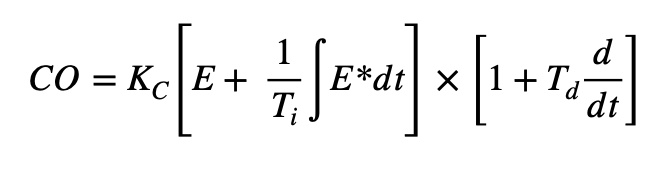
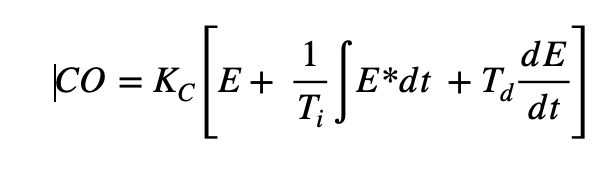
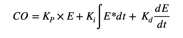
PID controller structure comes in three forms, known as the Interactive, Noninteractive, and Parallel:
- Interactive: The oldest arrangement of the P, I, and control modes is called the Interactive, Real, or Series form. The original pneumatic and electronic controllers had this form, and it is still found in some controllers today. In fact, the Ziegler-Nichols PID tuning rules were developed for this form.
- Noninteractive: The Noninteractive form is sometimes called the Standard, ISA algorithm or Ideal. Tuning rules such as the Cohen-Coon and Labda were designed for this form. Notice that, if no derivative term is used (i.e.,Td=0 ) the interactive and noninteractive are similar.
- Parallel: Many academic textbooks discuss only the parallel form of PID, and don’t review the other forms. Most of the DCs also use the parallel form. This algorithm is simple to understand but not intuitive to tune.
The reason is that it does not contain a controller gain that would normally affect all three modes. Instead, it has a proportional that affects only the P-mode. This means regulating P-gain should be supplemented by adjusting the I and D simultaneously.
So, not all PID controllers use the same equation. The same values of Kp, Ki, and Kd manifest differently across the above-mentioned forms.
Select an Appropriate Tuning Method
There is a large number of tuning procedures. This does not make them equally suitable for every process. It is critical to choose the right method. The most used and effective tuning methods include.
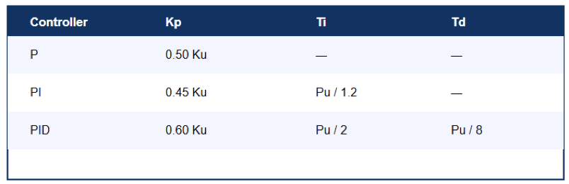
- Ziegler–Nichols (ZN): This method is suitable for used for rapid and aggressive tuning; Produces responsive loops with noticeable overshoot; Best for fast processes but not ideal for safety-critical or integrating processes.
- Process Reaction Curve: Step-based for testing the process; Useful for systems with long time constants where direct oscillation testing is risky.
- Cohen-Coon Method: Designed for processes with measurable dead time; Produces better performance than ZN for many slow loops.
- IMC (Internal Model Control)-Based Tuning: More robust and widely used in modern industries; It gives a balanced performance between speed and stability; Allows regulation (tuning) based on the desired closed-loop time constant.
- Relay Autotuning: Introduces controlled oscillations without pushing the system into instability; Modern PLCs and DCS platforms integrate relay-based autotune.
- Manual Tuning: Still used extensively by experienced engineers. The typical workflow:
- Increase Kp until the system starts to oscillate.
- Add Ki to mitigate the steady-state error.
- Introduce Kd to improve stability and decrease maximum overshoot.
The goal of each method is to reach acceptable settling time, robustness, balance overshoot and ease of application.
The best appropriate procedure depends on the process behaviors, safety requirements, and operational constraints.
So, the suggestion here is to choose the method that fits the process instead of the one you are used to.
Perform a Controlled Step Test
When a step test is performed accordingly, it discloses almost everything you need about the process. However, it has to be done correctly.
Best practices:
- Maintain the step significantly small not to disrupt production.
- Do not forget the recording of data at a good sampling rate.
- Before moving to the next step, give time for the process to settle.
- If your system is unsafe during step changes, then step tests should be avoided.
A clean, well-documented step test makes tuning much more predictable.
Tune for the Operating Objective, Not Just Stability
One of the common mistakes that appear during the tuning process is tuning the system just to avoid oscillations. This is not always the goal; there are other important factors, as explained below.
The main objectives to be fulfilled are.
- Settling time, i.e., do we desire a fast response (e.g., flow or pressure)?
- Is overshoot unacceptable (e.g., temperature in a reactor)?
- How about the stiction, is actuator wear a concern?
- Does energy-efficient necessary, smooth movement?
- Magnitudes of disturbances large and unpredictable?
Every loop has a control goal, so it is necessary to tune according this purpose
Use Derivative Action Carefully
Derivative control is proportional to the rate of the change of the error. This helps prevent overshoot and introduce damping to the system.
The effect of damping helps to eliminate oscillations. Although derivative control is powerful, its downside is it amplifies noise.
Hereunder are the good practices when it comes to the use of this control action:
- If your signal is being notably clean (noise-free), then feel free to use the derivative.
- Most of the controllers offer a filtering process, so check before applying filtering.
- In a slow process, if D is applied, it causes more harm than improvement.
- Large amount D value makes the actuator twitchy. It amplifies the small noise.
When a D term is applied in an adequate process, it makes a loop feel perfect, but when misused, it makes it jittery and loud.
Validate the Tuning with Real Disturbances
Once the numbers are set, the next step is to test the controller. The loops must be tested under real or simulated disturbances.
From the performed simulation, the following points must be observed:
- Does it recover smoothly?
- Is overshoot acceptable?
- Does the actuator avoid unnecessary movement (not chattering)?
- Is the process stable under different operating loads?
- Does the loop behave well at different setpoints?
Tuning isn’t successful until it works in real operating conditions.
Apply Anti-Windup Mechanisms
Integral windup is one of the most common causes of bad controller behavior. It happens when the actuator saturates. This means it hits the maximum or minimum values, and the integral term keeps accumulating error.
Once the actuator comes out of saturation, this causes the controller to slam the system trying to compensate.
Here are the tips on how to avoid this phenomenon:
- Use integrator clamping or an anti-windup solution.
- Use conditional integration.
- Limit the integral term.
- Use external reset feedback if the controller supports it.
Anti-windup has been shown to highly improve loop stability in different types of processes.
Documentation
This is one of the very important aspect not only during tuning, but also in engineering in general. It is one of the most overlooked best practices. Good documentation saves time keeping us up to date for the recently changes. It helps other engineers to track the past changes and provides a baseline for future work.
Before, during and even after the tuning process remember to record:
- The process conditions during tuning.
- The method used.
- The PID form and final values.
- Step test graphs.
- Observations before and after.
- Any special notes (nonlinearity, delays, disturbances, noise).
In the next sixth month, is difficult to recall the changes (modifications) you made today. So, to generates habit of documenting everything is a perfect best practice.
Key takeaways: PID Loop Tuning Best Practices
The tuning of the PID loop is crucial for optimal performance and system stability. The key importance here is to understand the role of proportional, integral and derivative terms.
Plus, to follow the systematic tuning techniques, will allow you to tune PID controllers effectively for different applications. This results to the control system that is more reliable and efficient.
In addition, even if the tuning process was successively achieved, it is recommended that the PID gains are continuously monitored and adjusted for safety, profit and energy efficiency.
FAQ: PID Loop Tuning Best Practices
What should I check before tuning?
Make sure sensors, actuators, and wiring work properly. Understand if the process is fast, slow, or has dead-time.
What is the simplest tuning approach?
Start with P-only, adjust until stable, then add I, and finally D only if needed.
Is Ziegler–Nichols still useful?
Yes, but only as a starting point. It often produces aggressive settings.
When should I avoid using derivative (D)?
Avoid D if the signal is noisy or the process is very fast.
How do I know a loop is over-tuned?
Oscillation, overshoot, or actuator “hunting” (constant movement).
How do I know a loop is under-tuned?
Slow response to setpoint or disturbances.
Should I tune loops one by one?
Yes. Interacting loops can confuse the results.
When should I retune?
If process conditions change, equipment ages, or the response becomes sluggish or unstable.
Do auto-tune features help?
They provide a good baseline, but manual adjustment is usually required.
When should I use advanced control methods?
If the process has dead-time, high interaction, or nonlinear behavior (cascade, feedforward, gain scheduling, etc.).