Becoming an engineer, specifically an industrial automation engineer, as in this case, requires a specific path.
The career is growing fast. It combines engineering principles with modern technology. This field focuses on automating industrial processes. In simple terms, it helps machines work on their own.
It allows factories and facilities to operate efficiently and safely. A formal education is essential.
Practical experience is just as important. You must also be willing to continue learning. This is one of the field its technology changes almost every day.
Continuous learning is a core requirement of this job. Take the following steps to enter this rewarding career. This article details a clear and practical overview of an industrial and automation engineer and how to become one.
Educational Foundations
The first step is education. This step builds your base knowledge. A strong academic foundation is critical.
It helps you understand how systems work. You must pursue a relevant degree program. This curriculum prepares you for real industrial challenges.
Right Degree
The minimum requirement is a Bachelor of Science (BSc) degree. This is usually expected by employers, and this degree should be in a related engineering field. Common choices include:
• Electrical Engineering (EE)
• Mechanical Engineering (ME)
• Chemical Engineering (ChE)
• Computer Engineering
• Industrial Engineering
Some universities offer dedicated degrees. These programs focus more on automation topics.
They might be in Automation Engineering or Control Systems Engineering to ensure the program is accredited.
Accreditation confirms the quality of the education and is very important for future job opportunities.
It also helps in understanding the functioning of real-world industries like aviation and plants.
The following figure indicates a diagram of recommended degree paths (EE, ME, ChE) leading to the Industrial Automation Engineer role.


Coursework and Focus
Focus on specific coursework during your studies. The field uses these subjects daily. Key subjects include:
• Control systems theory
• Instrumentation and measurement
• Programming languages such as Ladder Logic (LD), Python, and C++ are a must
• Robotics and fluid power
• Data acquisition and analysis
• Process control fundamentals
These courses build core knowledge. They explain how machines and systems behave. They provide a theoretical understanding. This theory supports effective design and troubleshooting.
Gaining Practical Experience
Theory is not enough. You must apply what you learn. Real systems behave differently from textbooks.
Practical application is vital in automation in order to have hands-on experience. Employers value experience very highly.
Internships and Co-ops
Seek internships enthusiastically. Usually, internships provide real-world exposure, so they should be applied for early and often. They show how factories actually operate. They allow you to apply classroom knowledge.
A co-op program is even better. Co-ops involve longer, structured work periods. They offer deeper immersion in the industry.
Target manufacturing firms, system integrators, or large industrial companies. These environments provide strong learning opportunities.
Personal Projects
Start personal projects. This shows motivation and curiosity. Build small automation systems at home.
Platforms like Arduino or Raspberry Pi are affordable and easy to learn, plus with programmable logic controllers (PLCs) if possible.
In the online market, used or old PLCs can be purchased. These projects demonstrate initiative. They also build valuable, practical skills. They look very good on a resume.
Technical Skills Acquisition
Master key technologies used in the field. Automation engineers use these tools daily. Proficiency in these tools is mandatory. Indeed, job opportunities always increase when you know more tools.
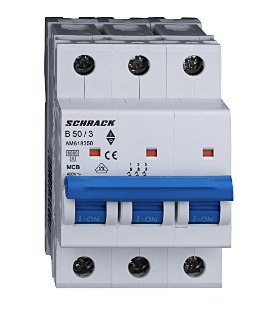
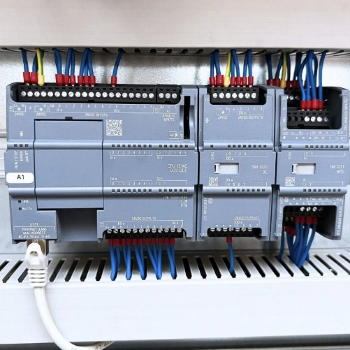
Programmable Logic Controllers (PLCs)
Always, the brains of automation systems are programmable controllers, especially PLCs. They control machines and processes. You must understand how to program them. Learn different programming languages.
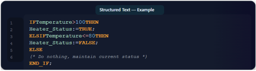
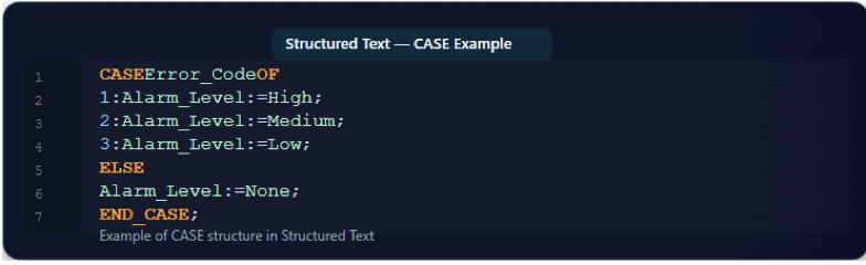
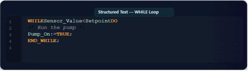
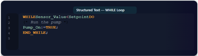
In this case, Ladder Logic (LD) is a place to start. Then you can proceed with Function Block Diagram (FBD) and Structured Text (ST). Depending on how big the project is, you can use Sequential Function Charts (SFC) and Instruction Lists (IL).
Allen-Bradley of Rockwell Automation, Siemens, and Mitsubishi are the common brands. Familiarity with their software suites is a major asset because it facilitates quick adaptation on the job.
Human-Machine Interfaces (HMIs) and SCADA
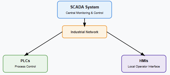
HMIs provide operator control. They allow humans to interact with machines. SCADA systems oversee entire processes. They collect and display data. You need to configure these systems. Learn to design effective screen layouts.
Clear screens reduce operator errors. Understand data visualization principles. These abilities are crucial for system safety and usability.
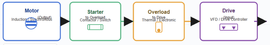
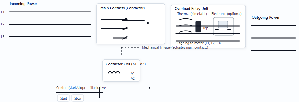
The next figure shows a diagram illustrating the interconnection between PLCs, HMIs, and the SCADA system in an automated plant.

Instrumentation and Field Devices
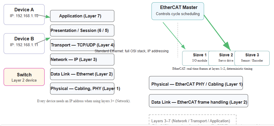
Understand sensors and actuators. These devices connect the physical world to control systems. Learn how they communicate with control systems. Plus, it is essential to practice with communication protocols.
These can include Profibus and Modbus. Furthermore, OPC UA and Ethernet/IP are essential. You must know how to select devices. You must also know how to troubleshoot wiring and signals.
Professional Certifications
Certifications enhance your credibility. They show commitment and knowledge. They validate your expertise. Employers often value certified professionals. Consider several options as you grow.
Industry Certifications
The standards for education are provided by the organization called The International Society of Automation (ISA). Additionally, it advances technology and enhances the expertise of automation professionals worldwide.
It is well respected worldwide. They offer valuable certifications. The Certified Automation Professional (CAP) is highly regarded.
It proves broad knowledge of automation systems. There are also certifications for specific vendors. Examples include Rockwell Automation certificates. These show expertise in particular product lines.
Professional Engineering License
It is also known as a PE license. This license is important for senior roles. It is required for signing off on official engineering designs. One should pass a Fundamental of Engineering (FE) exam to become a PE. Therefore, becoming a PE requires significant time and effort.
This procedure usually happens after graduation. Then, you should gain four years of experience working under a Professional Engineer (PE).
As the last step, taking and passing the Principles and Practice of Engineering (PE) exam is also important. This license signifies professional competence and ethics. It also increases career opportunities.
Job Search Process
Finding your first job requires strategy, and persistence and patience must be taken during this process. Focus your search efforts effectively. A planned approach improves success.
Networking
Networking is powerful. Many jobs are never advertised. Attend industry conferences. Join local ISA chapters.
Professionals can connect through platforms like LinkedIn, as personal connections often lead to a large number of jobs. Reaching out is essential because most professionals are willing to help.
Resume Building
Tailor your resume carefully. Avoid using a generic resume. Highlight relevant skills and projects. Show what you actually did.
Quantify achievements where possible. For example, “Reduced downtime by 15%.” Use keywords found in job descriptions. This helps with applicant tracking systems (ATS).
Interview Preparation
You should be ready for technical questions like PLCs. Also, about sensors and control loops. Review basic concepts before the interview.
Additionally, be ready for behavioral questions, as they can evaluate your teamwork skills and problem-solving abilities. Confidence can be improved by practicing the answers correctly beforehand.
Career Growth as well as Specialization
Your learning never stops because automation technology changes quickly. The field evolves rapidly, so embrace lifelong learning. Growth leads to better roles and pay.
Continuing Education
Nowadays, there is Industry 4.0 and IIoT. These two technologies must be learned. Without forgetting, consider learning about and understanding artificial intelligence (AI) and machine learning.
Without a doubt, these technologies shape the future of automation. Engage in online courses and participate in workshops and webinars, as they provide valuable insights. Always read industry publications. Small learning steps add up over time.
Specialization Areas
You can specialize as you gain experience. Specialization helps define your career path. Options include:
• Robotics engineering
• Process control
• Discrete manufacturing automation
• Building automation
• Cybersecurity for control systems
Specialization makes you an expert. Experts are in high demand. It opens up new opportunities and leadership roles.
Key takeaways: How to become an Industrial Automation Engineer
Becoming an industrial automation engineer is challenging. It requires dedication and hard work.
Learning never truly ends. But the career is rewarding. You solve complex problems daily to help machines work better.
You make industries safer and more efficient. The demand for these skills is high worldwide.
You will have strong job security. Follow this path with patience and effort. You can achieve this goal.
FAQ: How to become an Industrial Automation Engineer
What does an Industrial Automation Engineer do?
They design and maintain automated industrial systems.
What degree is required?
A bachelor’s degree in EE, ME, ChE, or a related field is required.
Is programming required?
Yes. PLC programming is essential.
Which PLC skills are important?
Ladder Logic, Structured Text, and troubleshooting.
Is hands-on experience necessary?
Yes. Practical experience is highly valued.
Are certifications mandatory?
No, but they improve job opportunities.
Can I enter without an engineering degree?
It’s possible, but the process is more challenging.
What industries hire automation engineers?
Manufacturing, energy, food, pharma, and automotive.
What software should I learn?
You should focus on learning about PLC, HMI, and SCADA platforms.
How long does it take to become one?
Typically, it takes 4–6 years, including experience.