If you walk into any industrial facility today, like a manufacturing plant, a water treatment station, or a commercial building’s mechanical room, you’ll find devices talking to each other over at least one of four protocols: Modbus, Profibus, EtherNet/IP, or BACnet.
The problem is that these protocols don’t speak the same language and weren’t designed for the same jobs, and choosing the wrong one for your application can lock you into years of integration headaches and unnecessary gateway hardware.
I work as an industrial automation engineer, and a large part of my job involves integrating gas detection controllers, PLCs, and building systems that were never designed to talk to each other.
I’ve commissioned Modbus RTU networks that ran flawlessly for years on a single twisted pair, and I’ve also spent long afternoons troubleshooting a Profibus segment because someone forgot a termination resistor.
This guide is the comparison I wish I’d had when I started: what each protocol actually is, where it wins, where it struggles, and how to choose between them.
Let’s start with the side-by-side view, then go deep on each one.
Quick Comparison Table: Modbus vs Profibus vs EtherNet/IP vs BACnet
| Feature | Modbus | Profibus | EtherNet/IP | BACnet |
|---|---|---|---|---|
| Year introduced | 1979 (Modicon) | 1989 (Germany) | 2001 (ODVA) | 1995 (ASHRAE) |
| Primary domain | General industrial, SCADA, energy | Factory & process automation | Discrete manufacturing, motion | Building automation (HVAC, lighting) |
| Physical layer | RS-485/RS-232 (RTU), Ethernet (TCP) | RS-485 (DP), MBP (PA), fiber | Standard Ethernet | MS/TP (RS-485), Ethernet (BACnet/IP) |
| Typical speed | 9.6–115.2 kbps (RTU); 100 Mbps+ (TCP) | 9.6 kbps – 12 Mbps (DP) | 100 Mbps – 1 Gbps | 9.6–115.2 kbps (MS/TP); 100 Mbps+ (IP) |
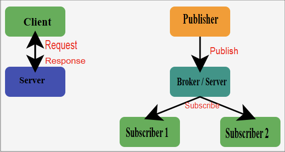
| Communication model | Master/slave (client/server) | Master/slave with token passing | Producer/consumer (CIP) | Peer-to-peer, client/server |
| Max devices per segment | 32 (RS-485, without repeaters) | 32 per segment, 126 per network | Limited by IP addressing | 32 per MS/TP segment (typical) |
| Data model | Registers and coils (raw) | Cyclic I/O data + parameters | Objects (CIP) | Standardized objects & properties |
| Determinism | Low | High (DP-V2 supports isochronous) | Moderate–high (with CIP Sync/Motion) | Low |
| Licensing cost | Free, open spec | Membership/certification fees | ODVA membership for vendors | Free, ASHRAE/ISO standard |
| Ease of implementation | Very easy | Moderate–complex | Moderate | Moderate |
| Best for | Simple, cheap, universal integration | High-speed factory I/O, process (PA) | Rockwell/Allen-Bradley ecosystems | Commercial building systems |
Bookmark that table but don’t choose a protocol from a table alone. Context is everything, so let’s look at each protocol the way you’d actually encounter it in the field.
What Is an Industrial Communication Protocol?
An industrial communication protocol is a standardized set of rules that lets controllers, sensors, actuators, drives, and supervisory systems exchange data reliably in harsh, time-sensitive environments. Unlike office networking, industrial protocols must handle the following.
- Determinism: a drive command that arrives 200 ms late can scrap product or damage equipment.
- Electrical noise: motors, VFDs, and welders create interference that would cripple consumer-grade communication.
- Long distances: cable runs of hundreds of meters across a plant floor or building riser.
- Decades-long lifecycles: industrial equipment installed in 1998 may still need to communicate today.
That last point explains why a protocol from 1979 (Modbus) is still everywhere in 2026. Industrial networks evolve slowly and coexist messily, which is exactly why understanding all four major protocols matters.
Modbus: The Universal Translator of Industry
What It Is
Modbus was created by Modicon (now Schneider Electric) in 1979 for use with its PLCs, and it became the de facto standard for industrial serial communication largely because Modicon published the specification openly. Anyone could implement it without paying royalties, and nearly everyone did.
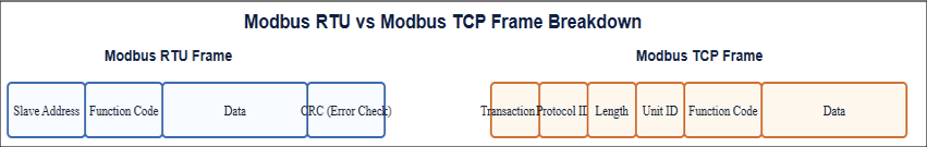
Modbus comes in three main flavors.
- Modbus RTU: binary encoding over RS-485 or RS-232 serial lines. The workhorse variant.
- Modbus ASCII: human-readable encoding over serial. Rare today.
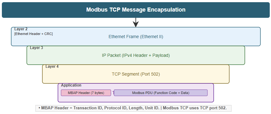
- Modbus TCP/IP: the same register-based data model wrapped in standard Ethernet TCP frames.
How It Works
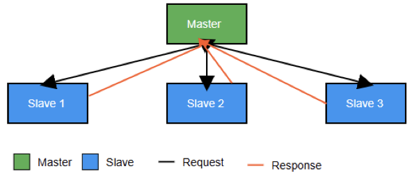
Modbus uses a strict master/slave (now officially “client/server”) architecture. The master polls each slave device by address, requesting or writing data organized into four simple data types: coils (read/write bits), discrete inputs (read-only bits), holding registers (read/write 16-bit words), and input registers (read-only 16-bit words).
That simplicity is both Modbus’s superpower and its biggest limitation. There is no standardized meaning for any register; register 40001 might be temperature on one device and pump speed on another. You must have the vendor’s register map to integrate anything.
Where I See Modbus in the Field
In my work with gas detection systems, Modbus RTU is everywhere. Fixed gas controllers almost universally offer a Modbus RTU output so a PLC or SCADA system can read gas concentrations, alarm states, and fault conditions. It’s the lowest-common-denominator integration path: if two industrial devices need to exchange a handful of values and cost matters, Modbus is usually the answer.
Strengths
- Free and open: no licensing, no certification required.
- Trivially simple: An engineer can implement a Modbus driver in an afternoon; virtually every SCADA, HMI, and PLC platform supports it natively.
- Ubiquitous: power meters, VFDs, gas detectors, flow meters, solar inverters, generators… if it’s industrial, it probably speaks Modbus.
- Modbus TCP scales: moving to Ethernet removes the serial speed ceiling while keeping the same data model.
Weaknesses
- No device interoperability standard: every integration requires a register map.
- Master/slave polling only: slaves cannot initiate communication (no unsolicited alarms in standard Modbus).
- Slow on serial:32 devices polled at 9,600 baud gets sluggish fast.
- No built-in security: Modbus TCP has no native authentication or encryption (Modbus Security, using TLS, exists but adoption remains limited).
Best Use Cases
Energy monitoring, SCADA telemetry, gas detection integration, solar and generator monitoring, and any “just get the data from device A to system B” project on a budget.
Profibus: The European Factory Powerhouse
What It Is
Profibus (PROcess FIeld BUS) emerged from a German government-backed project in 1989 and became the dominant fieldbus in European manufacturing, heavily championed by Siemens.
It’s a true fieldbus: designed from the ground up for fast, deterministic, cyclic exchange of I/O data between controllers and field devices.
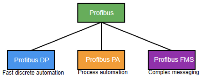
Two variants matter
- Profibus DP (Decentralized Peripherals): high-speed RS-485 communication (up to 12 Mbps) for factory automation: remote I/O, drives, and valves.
- Profibus PA (Process Automation): designed for process industries, using MBP transmission that delivers power and data on the same pair and supports intrinsically safe installations in hazardous areas.
How It Works
Profibus uses a hybrid token-passing and master/slave scheme. Multiple masters can exist on one network; a token circulates among masters, and whichever master holds the token polls its assigned slaves.
Data exchange is cyclic and deterministic; each slave is guaranteed a communication slot every bus cycle, which is exactly what fast machinery requires.
Device integration is standardized through GSD files, which describe a device’s capabilities to the engineering tool. This is a significant step up from Modbus’s “read the manual and hope” approach.
Strengths
- Deterministic and fast: 12 Mbps with guaranteed cycle times; DP-V2 adds isochronous mode for motion control.
- Massive installed base: hundreds of millions of nodes worldwide, especially in European plants and anywhere Siemens PLCs dominate.
- Profibus PA solves process problems: bus-powered instruments and intrinsic safety for Zone 1 hazardous areas, which matters enormously in oil & gas and chemical plants.
- Robust diagnostics: devices report standardized diagnostic data, speeding up troubleshooting.
Weaknesses
- Wiring discipline required: termination, stub lengths, and segment design must be correct, or you’ll chase intermittent faults. (I’ve been there. Check your terminators first.)
- Declining trajectory: Profinet, its Ethernet-based successor, is where Siemens and the PI organization now invest. New greenfield projects increasingly skip Profibus DP.
- Cost and complexity: special connectors, repeaters, and engineering tools add up.
- Not a building or IT protocol: it lives and dies on the plant floor.
Best Use Cases
Existing Siemens-centric factories, process plants needing intrinsically safe instrument networks (PA), and high-speed remote I/O where deterministic cycles are non-negotiable.
EtherNet/IP: Industrial Ethernet, American Style
What It Is
EtherNet/IP (the “IP” stands for Industrial Protocol, not Internet Protocol, a naming decision that has confused engineers for two decades) was introduced in 2001 and is managed by the ODVA.
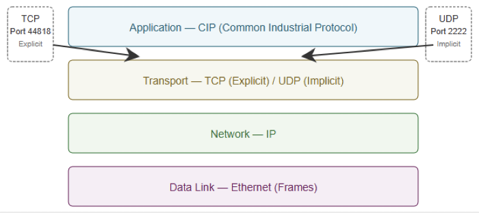
It adapts the Common Industrial Protocol (CIP), the same object-oriented application layer used by DeviceNet and ControlNet, to run over standard Ethernet and TCP/UDP.
It is the flagship protocol of the Rockwell Automation / Allen-Bradley ecosystem and one of the most widely used industrial Ethernet protocols in North America.
How It Works
EtherNet/IP uses a producer/consumer model rather than pure polling. Two message classes do the work:
- Explicit messaging (TCP): request/response transactions for configuration, diagnostics, and non-time-critical data.
- Implicit messaging (UDP): cyclic, real-time I/O data multicast or unicast from producers to consumers at configured RPIs (requested packet intervals).
Because CIP defines standardized object models for device types (a drive object, a valve object, and an analog input object), devices from different vendors expose data in predictable structures, a genuine interoperability advantage over Modbus.
Extensions like CIP Safety (functional safety over the same wire), CIP Sync (IEEE 1588 time synchronization), and CIP Motion (coordinated servo control) let one network handle standard I/O, safety, and motion simultaneously.
Strengths
- Standard Ethernet infrastructure: commercial switches, familiar IT tools, easy integration with MES/ERP layers.
- High performance: 100 Mbps to gigabit speeds with real-time I/O via UDP.
- Rich object model: standardized device profiles reduce integration guesswork.
- Safety and motion on one network: CIP Safety and CIP Motion eliminate separate, dedicated networks.
- Deep Rockwell integration: if your plant runs ControlLogix or CompactLogix PLCs, EtherNet/IP is the path of least resistance.
Weaknesses
- Network engineering matters: implicit messaging multicast traffic demands managed switches with IGMP snooping; a flat, unmanaged network can melt down.
- Vendor gravity: While open, the ecosystem orbits Rockwell; in Siemens territory, you’ll fight the current (Profinet dominates there).
- Cost: EtherNet/IP-native field devices typically cost more than their Modbus equivalents.
- Security surface: being standard Ethernet means it inherits every IT attack vector; CIP security exists but requires deliberate deployment.
Best Use Cases
Discrete manufacturing (automotive, packaging, food & beverage) in Rockwell-based plants, integrated safety systems, coordinated motion applications, and any architecture where plant-floor data must flow up to IT systems.
BACnet: The Language of Buildings
What It Is
BACnet (Building Automation and Control Network) was developed by ASHRAE beginning in 1987 and published in 1995, later becoming ISO standard 16484-5. Unlike the other three protocols, BACnet wasn’t built for factories.
It was built for buildings: HVAC, lighting, access control, fire alarm interfaces, and energy management.
The two variants you’ll actually encounter:
- BACnet MS/TP token-passing over RS-485, used at the field level for VAV boxes, thermostats, and unitary controllers.
- BACnet/IP: BACnet messages over UDP/IP Ethernet, used at the automation and supervisory levels.
If you want to go deeper on the BACnet family, I’ve written a dedicated guide to the BACnet protocol and a full comparison of BACnet/IP vs BACnet MS/TP
How It Works
BACnet’s defining feature is its standardized object model. Every BACnet device exposes its data as objects: Analog Input, Binary Output, Schedule, Trend Log, and Alarm, and each object has standardized properties (Present_Value, Units, and Status_Flags).
A supervisory workstation can discover devices on the network, browse their objects, and understand what the data means without a register map.
That’s the fundamental philosophical difference from Modbus: BACnet standardizes meaning, not just transport. Services like Who-Is/I-Am (discovery), COV (change-of-value subscriptions instead of constant polling), scheduling, trending, and alarming are all part of the standard itself.
Strengths
- True interoperability: mix chillers, air handlers, and lighting controllers from different vendors under one front-end.
- Built-in building services: scheduling, trending, and alarm management are native, not bolted on.
- Free, open ISO standard: no licensing barriers.
- Dominant in its domain: BACnet is the overwhelming standard for commercial HVAC and building management systems worldwide.
Weaknesses
- Not deterministic: BACnet has no place controlling a servo axis or a high-speed line; buildings change in seconds and minutes, not milliseconds.
- MS/TP speed limits: token passing over RS-485 tops out at 115.2 kbps, and poorly designed segments get slow.
- “Standard” doesn’t mean identical: vendors implement different BIBBs (BACnet Interoperability Building Blocks); always check the device’s PICS document before assuming compatibility.
- Security history: legacy BACnet had essentially no security; BACnet Secure Connect (BACnet/SC) adds TLS-based security, but retrofitting existing buildings takes time.
Best Use Cases
Commercial building automation, HVAC control, campus energy management, smart building integrations, and any project where multi-vendor building equipment must operate under a single management system.
Head-to-Head: How the Four Protocols Really Differ
Speed and Determinism
For raw speed and guaranteed timing, the ranking is clear: EtherNet/IP and Profibus DP lead, Modbus TCP is fast but non-deterministic, and Modbus RTU and BACnet MS/TP trail far behind on serial links.
If your application involves motion control or fast interlocking, Modbus and BACnet are out of the conversation entirely.
Data Philosophy: Raw Registers vs Standardized Objects
This is the comparison most guides miss, and it matters more than baud rates:
| Protocol | Data philosophy | Integration effort |
|---|---|---|
| Modbus | Raw registers, no standardized meaning | High need for vendor register maps |
| Profibus | Cyclic I/O defined by GSD files | Moderate GSD standardizes structure |
| EtherNet/IP | CIP objects with device profiles | Moderate-to-low profiles standardize common devices |
| BACnet | Fully standardized objects & services | Low (within building domain) discovery built in |
Modbus makes the protocol easy and the integration hard. BACnet and EtherNet/IP invert that: more protocol complexity, less guesswork per device.
Topology and Physical Layer
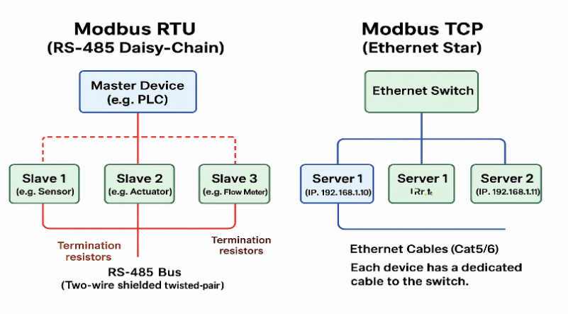
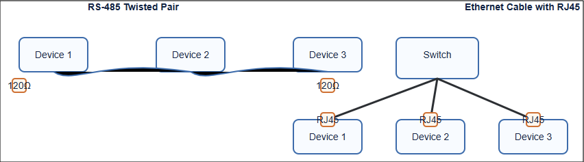
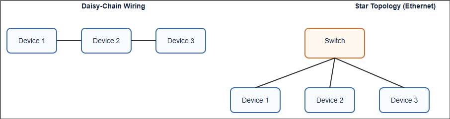
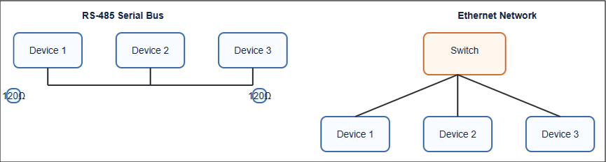
Modbus RTU, Profibus DP, and BACnet MS/TP all commonly ride on RS-485 twisted-pair, daisy-chained, with termination at both ends, with roughly 32 devices per segment before repeaters.
If you’ve wired one, the physical discipline transfers to the others (and most of the “protocol problems” I get called about turn out to be wiring problems: missing terminators, star topologies, or grounding issues).
Modbus TCP, EtherNet/IP, and BACnet/IP all use standard Ethernet, which means switches, VLANs, and star topologies plus the responsibility of proper network design and segmentation.
Cost of Ownership
From cheapest to most expensive in typical deployments: Modbus RTU → BACnet MS/TP → Modbus TCP/BACnet/IP → Profibus → EtherNet/IP.
The Ethernet protocols cost more per device but often less per data point at scale, because engineering time and integration effort dominate real project budgets.
Industry Alignment
- Modbus: energy, utilities, OEM devices, SCADA, gas detection, solar.
- Profibus: European manufacturing, process industries, Siemens installations.
- EtherNet/IP: North American discrete manufacturing, Rockwell installations.
- BACnet: commercial buildings, HVAC, campus facilities.
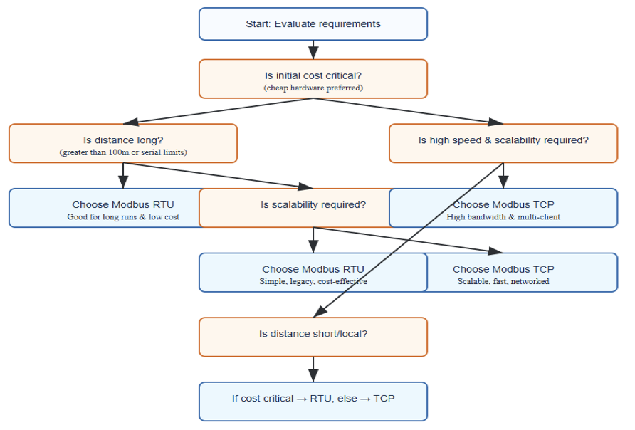
How to Choose: A Practical Decision Framework
After years of integration work, here’s the decision process I actually use.
What does your controller ecosystem already speak?
If the plant runs Allen-Bradley, EtherNet/IP is the default. Siemens shop? Profibus (or more likely Profinet for new work). Building management system? BACnet. Fighting your installed base is expensive.
What do your field devices offer?
Check the spec sheets. A device that only offers Modbus RTU decides for you or adds a gateway to your bill of materials.
How fast does the data need to be?
Millisecond interlocks and motion → EtherNet/IP or Profibus DP. Seconds-scale monitoring → Modbus or BACnet is fine and cheaper.
Is this a building or a process?
HVAC, lighting, and energy in a commercial building → BACnet, full stop. Trying to run a building on EtherNet/IP or a factory on BACnet means swimming upstream against every vendor’s product catalog.
Who maintains it for the next 15 years?
Choose the protocol your local technicians and integrators actually know. The “best” protocol nobody on site can troubleshoot is the worst protocol.
When in doubt for simple monitoring, choose Modbus
It’s the protocol equivalent of a universal adapter, imperfect, but it always gets the data through.
Mixing Protocols: Gateways and the Real World
Here’s the truth no protocol comparison tells you: you will rarely work with just one. A typical facility I encounter has a Rockwell PLC on EtherNet/IP, gas detection controllers on Modbus RTU, and the building’s air handling on BACnet all needing to appear on one dashboard.
Protocol gateways make this work. Devices from vendors like HMS (Anybus), MOXA, Red Lion, and ProSoft translate between virtually any pair of these protocols.
A Modbus-to-BACnet gateway, for example, lets a building management system read a gas controller’s Modbus registers as native BACnet objects.
When specifying a gateway, watch three things: point capacity (how many data values it can map), update rate under full load, and configuration software quality, because you’ll live inside that mapping tool during commissioning.
Future-Proofing: Where Industrial Communication Is Heading
The four protocols in this guide aren’t going anywhere soon — the installed base is simply too vast. But three trends are reshaping the landscape:
Ethernet everywhere
Serial fieldbuses are in slow decline for new projects: Profibus is giving way to Profinet, Modbus RTU to Modbus TCP, and BACnet MS/TP to BACnet/IP.
Ethernet-APL is even bringing two-wire, hazardous-area Ethernet to process instruments.
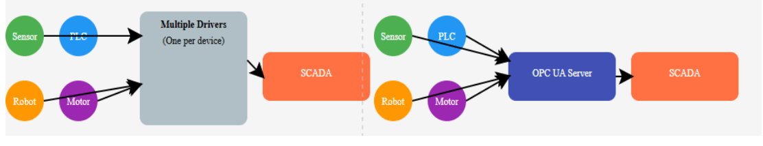
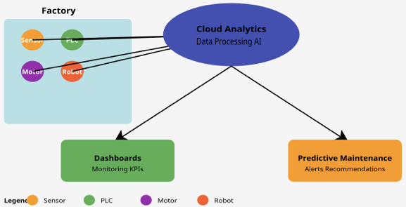
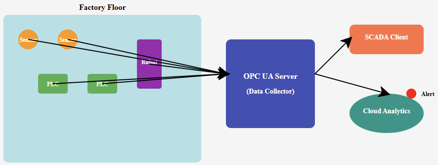
OPC UA and MQTT for the IT layer
Rather than replacing fieldbuses, protocols like OPC UA and MQTT (with Sparkplug B) increasingly sit above them, moving contextualized data to historians, clouds, and analytics platforms. I’ve covered MQTT in depth in a separate guide here on Control Circuitry.
Security by design
Modbus Security, CIP Security, and BACnet/SC all bring TLS-based protection to protocols born in a more trusting era. Expect security requirements, not speed, to drive the next wave of upgrades.
The engineer’s takeaway: learn the four classics in this guide and one northbound protocol (OPC UA or MQTT), and you’ll be equipped for both today’s brownfield plants and tomorrow’s connected ones.
Frequently Asked Questions
Which industrial communication protocol is the most widely used?
Measured by sheer number of devices, Modbus is generally considered the most widely deployed industrial protocol in the world, thanks to nearly five decades of royalty-free availability across every industrial sector.
Within specific domains, however, EtherNet/IP and Profinet lead industrial Ethernet in manufacturing.
Profibus retains an enormous installed base in process industries, and BACnet dominates commercial buildings.
Is Modbus TCP the same as EtherNet/IP?
No. Both run over standard Ethernet, but they are entirely different protocols. Modbus TCP wraps the simple Modbus register model in TCP frames, while EtherNet/IP implements the object-oriented CIP application layer with producer/consumer real-time messaging.
A Modbus TCP device and an EtherNet/IP device cannot communicate directly without a gateway or a controller that supports both.
Can BACnet be used in factories or Modbus in buildings?
Technically yes, and it happens all the time in small ways. Modbus power meters inside buildings are extremely common, and BACnet interfaces appear on factory HVAC.
But each protocol’s ecosystem (device availability, engineering tools, integrator expertise) is optimized for its home domain.
Use BACnet for building systems, industrial protocols for machines, and gateways where the two worlds meet.
What replaced Profibus?
Profinet, the Ethernet-based successor promoted by the same organization (PI) and by Siemens, is the standard choice for new Siemens-centric projects.
Profibus DP remains fully supported and hugely installed, and Profibus PA continues to serve hazardous-area process instrumentation, but new development investment has clearly shifted to Profinet.
Do I need special cables for these protocols?
For the serial variants (Modbus RTU, Profibus DP, BACnet MS/TP), yes, use shielded twisted-pair cable rated for RS-485 with the correct characteristic impedance, proper termination resistors at both ends of the trunk, and daisy-chain topology.
Profibus specifies its own cable types (typically purple-jacketed Type A). Ethernet-based variants use standard industrial Ethernet cable (Cat5e/Cat6), ideally shielded in electrically noisy environments.
Which protocol should a new automation engineer learn first?
Start with Modbus. It’s simple enough to fully understand in days; it teaches the fundamentals of registers, polling, and serial communication, and you will encounter it constantly regardless of industry.
Then learn the Ethernet protocol dominant in your region or employer’s ecosystem: EtherNet/IP in Rockwell territory, Profinet in Siemens territory, and add BACnet if you touch building systems.
Final Thoughts
There is no “best” industrial communication protocol; there is only the best fit for your devices, your ecosystem, your speed requirements, and your maintenance team.
Modbus wins on simplicity and universality, Profibus on deterministic fieldbus performance in process and factory settings, EtherNet/IP on integrated high-performance manufacturing networks, and BACnet on multi-vendor building interoperability.
In practice, the most valuable skill isn’t picking one protocol. It’s understanding how all four think so you can make them cooperate. That’s what modern industrial integration actually looks like.
Have a protocol integration question or a war story about a missing termination resistor? Drop it in the comments. I read every one.