In the world of industrial automation and control systems, machines must constantly exchange information to ensure smooth, safe, and efficient operation. The way they “talk” to each other is through signals.
These signals transmit information about measurements such as temperature, so that a central controller like a PLC (Programmable Logic Controller) or DCS (Distributed Control System), can understand what is happening in the process and take corrective action if needed.
Two of the most widely used methods of transmitting these measurements are the analog signal of 0–10V voltage signal and the 4–20 mA current loop.
This article explores these two signal standards in depth. We will examine how they work, their advantages and disadvantages, and the scenarios where one is better suited than the other.
The Voltage Signal (0 – 10V)
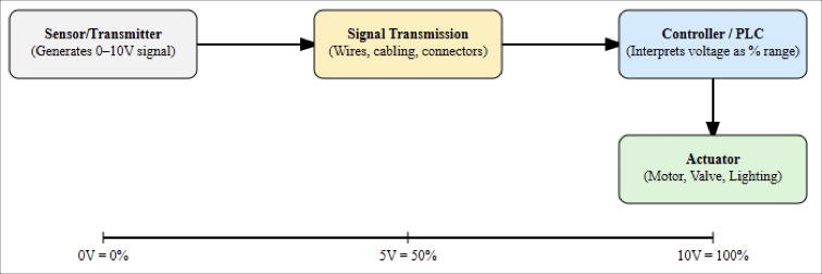
The 0–10V analog signal is a method where a sensor, transmitter, or field device generates a voltage that varies between 0 volts and 10 volts. This voltage represents a measurement in the physical world.
For instance:
- 0V might represent 0% of the measured range (e.g., 0 liters/min of flow).
- 10V might represent 100% of the measured range (e.g., 100 liters/min of flow).
The receiving controller interprets this voltage proportionally. If the signal reads 5V, the system understands this as 50% of the measurement range.
How a 0–10V Signal Works
The principle is straightforward: the transmitter outputs a voltage corresponding to the measurement, and the receiving device reads that voltage. The relationship is usually linear, which can be mathematically expressed as:


For example, if the sensor range is 0–200 °C and the output is 0–10V, then at 7.5V the controller interprets:

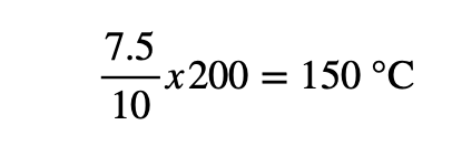
The wiring typically involves three wires:
- Positive power supply
- Ground
- Signal wire carrying the 0–10V output

Advantages of 0–10V
Simplicity and low cost
The 0–10V approach is easy to understand, implement, and troubleshoot. Devices that use this method are usually less expensive, making it attractive for cost-sensitive projects.
Widespread compatibility
Many HVAC systems, building automation devices, and older controllers support 0–10V directly, ensuring plug-and-play operation.
Parallel measurement
A technician can measure the signal with a multimeter without interrupting the circuit, which is helpful for maintenance and diagnostics.
Disadvantages of 0–10V
Susceptibility to electrical noise
Voltage signals can be corrupted by electromagnetic interference (EMI). Nearby motors, inverters, or power transformers may induce unwanted voltages that distort the reading.
Voltage drop over distance
As the signal travels along long cables, resistance causes voltage loss. For example, over 100 meters of cable, the measured voltage may drop enough to introduce noticeable errors.
Fault detection difficulties
If the controller sees 0V, it cannot distinguish whether the measurement is truly zero or if there is a wiring fault or sensor power failure.
Separate power supply requirement
The sensor often requires its own power lines in addition to the signal line, leading to more complex wiring.
The Current Loop (4–20 mA)
The 4–20mA standard is one of the most enduring and reliable methods for transmitting process signals in industry.
Instead of sending voltage, the transmitter regulates a current that flows in a closed loop.
- 4mA represents the minimum process value (not zero).
- 20mA represents the maximum process value.
- Any reading below 4mA indicates a fault condition, such as a broken wire.
This feature is called the “live zero.”
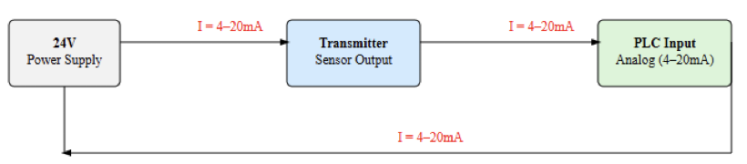
How a 4–20mA signal works
A 4–20mA loop typically consists of three components:
- Power source (usually 24V DC)
- Transmitter (sensor device)
- Receiver (PLC input or monitoring system)
All these components are connected in series so that the same current flows through each. Mathematically:

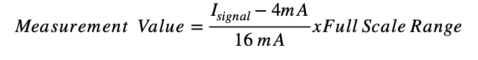
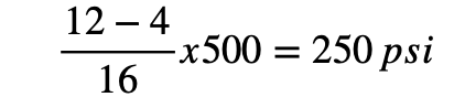
Example: If the measured range is 0–500 psi and the signal is 12mA, then:


Advantages of 4–20mA
High noise immunity
Current loops are much less affected by EMI than voltage signals, which makes them ideal for heavy industrial environments.
No signal degradation with distance
Unlike voltage, current does not drop across long cable runs. A 4–20mA loop can run hundreds of meters without losing accuracy.
Built-in fault detection
The live zero (4mA) ensures that a 0mA reading always indicates a problem, allowing quick troubleshooting.
Two-wire simplicity
Many transmitters are loop-powered, meaning the same two wires provide both power and signal, reducing installation costs.
Intrinsically safe
Because of the low power involved, 4–20mA devices can be used safely in hazardous areas such as oil refineries, chemical plants, or gas pipelines.
Disadvantages of 4–20 mA
Higher cost and complexity
Devices and transmitters that support current loops are typically more expensive and use more sophisticated electronics.
Measurement requires breaking the loop
To insert a multimeter and measure current, the loop must be opened, which interrupts operation. Specialized tools like loop calibrators are often used instead.
Limited to one signal per loop
Each 4–20mA loop transmits a single process variable. If multiple measurements are needed, additional loops (and wiring) are required.
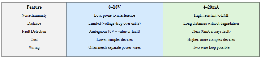
Comparing 0–10V and 4–20mA
The main differences between the two standards can be summarized as follows:

Choosing the Right Signal for Your Application
The decision between 0–10V and 4–20mA is application-specific.
Choose 0–10V when:
- The sensor is physically close to the controller (short cable runs).
- The environment is electrically quiet, with minimal interference.
- The project budget is limited, and cost efficiency is the priority.
- The system requires straightforward installation.
- Typical examples: HVAC systems, lighting controls, small building automation setups.
Choose 4–20mA when:
- The signal must travel long distances without accuracy loss.
- The environment contains heavy electrical noise.
- Built-in fault detection is critical for safety and reliability.
- Simplified wiring is preferred, especially with loop-powered devices.
- The system must comply with safety regulations in hazardous industries.
- Typical examples: chemical plants, refineries, power plants, water treatment facilities.
Key Takeaways: What Is The Difference between 0–10V and 4–20mA
This present article explained about two signal standards in depth, 0–10V and 4–20 mA.
It detailed how these signals they work, their advantagesanddisadvantages, and the scenarios where one is better suited than the other.
From this discussion, we are able to say that both 0–10V and 4–20mA have served industry reliably for decades, and each continues to play an important role in automation today.
So, the 0–10V standard provides simplicity, affordability, and compatibility with legacy systems.
It is best suited for short distances and environments with minimal electrical interference.
On the other hand, the 4–20 mA current loop is considered the workhorse of industrial measurement.
Its robustness against noise, ability to travel long distances without loss, and built-in fault detection make it indispensable in harsh industrial environments.
Even though modern plants are increasingly adopting digital communication protocols such as Ethernet/IP, HART, and Foundation Fieldbus, analog signals will remain valuable because of their simplicity, reliability, and low infrastructure needs.
Ultimately, the choice between 0–10V and 4–20mA can be summarized as: choose 0–10V when cost and simplicity matter most, and finally, choose 4–20mA when reliability, distance, and robustness are critical.
FAQ: What Is The Difference between 0–10V and 4–20mA
Why is 4-20 mA often preferred over 0-10 V in industrial analog signaling?
There are several reasons:
- Live zero / Fault detection: Because 4 mA represents the lowest valid measurement, any reading below that (e.g. 0 mA) signals a fault (broken wire, power failure, etc.). With 0-10 V, 0 V can mean either a valid zero or a problem.
- Better for long wiring runs: The current loop is less affected by voltage drop in long cables; voltage signals are more subject to losses over long wires.
- Less susceptible to electrical noise (EMI): Since noise tends to introduce undesired voltages, a current loop is more robust against such interference.
- Simplified wiring / loop powering: With the 4-20 mA loop, the same two wires can often supply power and carry the signal. This can reduce wiring complexity and cost in some installations.
What are the disadvantages or trade-offs of using 4-20 mA compared to 0-10 V?
Yes, while 4-20 mA has many advantages, there are trade-offs:
- Cost / hardware complexity: Devices that generate or receive 4-20 mA signals often require more complex electronics, which can make them more expensive.
- Measurement is less convenient: To measure the current in the loop, one often needs to break the loop (insert an ammeter in series), which disrupts the signal. With 0-10 V, one can often measure in parallel without interrupting the loop.
- Signal per loop limit: Each 4-20 mA loop typically carries one process variable; if multiple signals are needed, multiple loops are required. Wiring and component count can increase.
When is 0-10 V still a good choice over 4-20 mA?
Situations where 0-10 V may be perfectly adequate:
- Short cable runs and low electrical noise environments. In such cases, voltage drop and interference are less of an issue.
- When cost is a key constraint and simpler / less expensive components are needed. Some sensors and controllers may support 0-10 V outputs more cheaply.
- When existing equipment or controllers already use or expect 0-10 V inputs/outputs. Integration simplicity matters.
How easily can a 0-10 V system detect faults compared to a 4-20 mA system?
Fault detection is stronger in 4-20 mA systems:
- If the loop current drops to 0 mA, that’s a clear fault.
- In 0-10 V, a reading of 0 V could mean “zero value” or “no signal / broken wire / power off.” The system cannot reliably distinguish without additional diagnostics.
What about environmental factors such as noise and resistance? How do they affect each signal type?
Environmental factors play a big role:
- Electrical noise (EMI): Voltage signals (0-10 V) are more prone to being perturbed by induced voltages from nearby equipment. In contrast, current loops (4-20 mA) are more immune.
- Wire resistance and length: Long cables have resistance, which causes voltage drop in voltage-based signals. Current signals are less affected because the same current flows. However, there’s still some drop due to wire resistance affecting the power supply side, but signal loss is much less.
Are there applications where 4-20 mA is essentially mandatory?
Yes, particularly in industrial, harsh, or safety-critical applications:
- In process control (chemical plants, refineries, oil & gas) where distances are long, and environment is electrically noisy.
- Where intrinsically safe instrumentation is required (i.e. in hazardous areas where spark risks must be minimized). Because current loops can be designed in safer ways.
- When fault detection is critical for safety or maintenance. Continuous monitoring and early detection of failures are more reliable with 4-20 mA loops.
Does the cost difference between sensors/devices for 0-10 V vs 4-20 mA remain large?
The gap is narrowing, but some difference remains:
- Historically, 4-20 mA sensors and transmitters were more expensive because of the extra electronics needed (current regulation, loop interface, etc.)
- But as more devices support both kinds of outputs, and manufacturing advances, the price differential is lessening. For many applications, the extra cost is justified by the robustness and fault-tolerance of the 4-20 mA approach.
Are there situations where 0-10 V is not suitable at all?
Yes, especially when any of these conditions apply:
- The wiring distance is long enough that voltage drop would degrade the accuracy significantly.
- The environment has high electromagnetic interference (motors, welding, large currents nearby).
- Fault detection is required (you need to reliably know when something is wrong).
- Power needs to be delivered over the same lines (“loop powered” scenario). If a sensor has to draw power plus send a voltage signal, then separate wiring or power supply may complicate things.
