Modern industrial systems need sensors to track, control, and so improve processes. Sensors serve as the main interaction between control systems and the physical world. From chemical plants and smart factories to power plants and manufacturing lines.
They convert physical elements like pressure and flow into valuable electrical signals. They do so to temperature as well as position. Without reliable sensors, automation, safety, and efficiency would not be achievable.
Sensor technology is always growing in accuracy and dependability. Also, networking industries embrace more and more degrees of digitization. Plus, Industrial Internet of Things (IIoT).
Engineers, technicians, and decision makers are engaged in industrial automation. In order to know the several kinds of industrial sensors and how they operate.
The main kinds of industrial sensors are examined in this article. Also clarifies their functioning principles and covers their frequent uses.
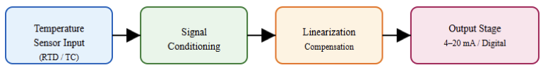
Temperature Sensors
Among the most frequently measured parameters in industrial procedures is temperature.
Applications include chemical reactors and food processing. It may include HVAC systems and boilers.
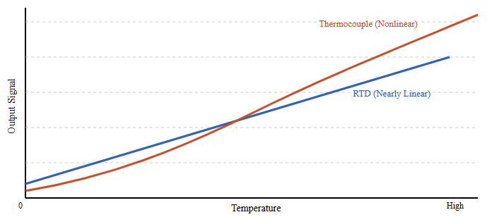
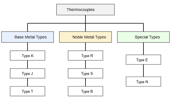
Without forgetting, furnaces also employ temperature sensors. Thermocouples and resistance temperature sensors (RTDs) are among the most commonly used industrial temperature sensors. Also, without forgetting the thermistors.
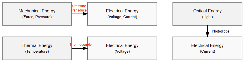
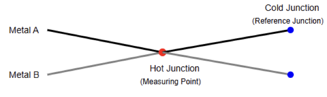
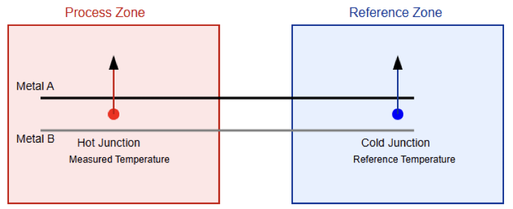
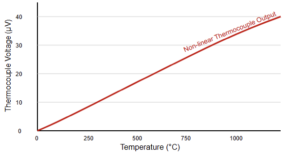
Working on the Seebeck effect, thermocouples produce a voltage. This phenomenon occurs when two different metals are linked.
Then, both were introduced to a temperature differential. Suitable for demanding industrial conditions, they are strong, cheap, and able to measure very high temperatures.
Usually consisting of platinum, RTDs measure temperature by relating resistance variations to temperature.
Often employed in precise industrial uses, they provide great accuracy and long-term stability.
Usually employed where quick reaction is needed. Thermistors have excellent sensitivity over a small temperature range.
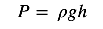
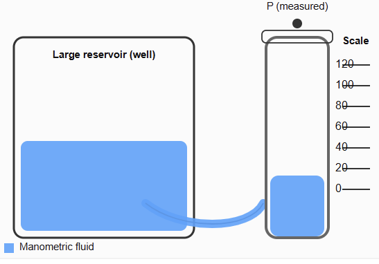
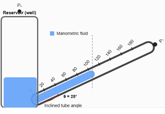
Pressure Sensors
Critical in sectors including oil and gas and power production, pressure sensors have an important function.
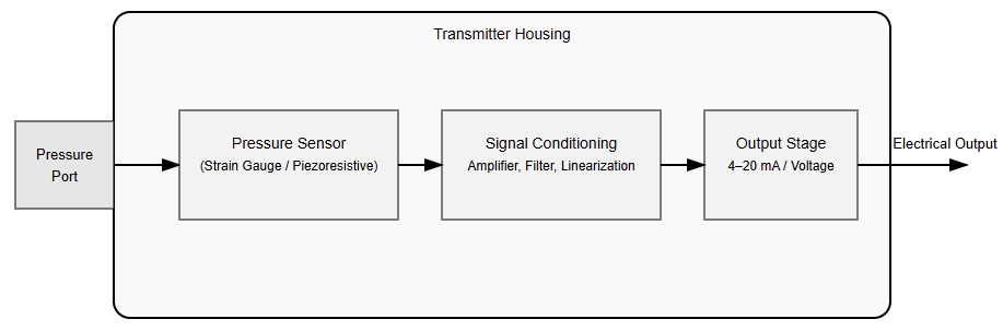
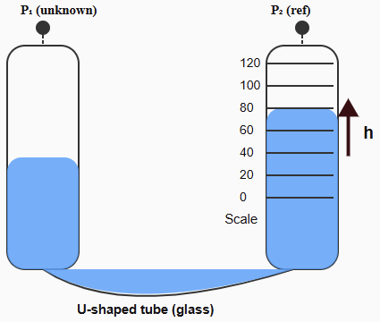
Include in hydraulics and process manufacturing. These detectors translate the force applied by a liquid or gas into an electrical signal. Piezoresistive, capacitive, and strain-gauge-based sensors are among the most used.
Piezoresistive pressure sensors depend on the shift in electrical resistance of a semiconductor material under mechanical stress. Their small size and great sensitivity make them quite popular.
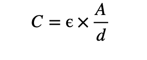
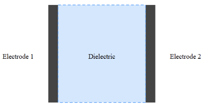
Particularly well-suited for low-pressure measurements. These sensors record variations in capacitance brought on by diaphragm deflection under pressure.
Strain-gauge pressure sensors provide dependability and robustness in industrial applications.
They achieve this by detecting deformation using bonded or deposited strain gauges on the diaphragm.
Flow Sensors
Monitoring fluids and gases in pipelines totally depends on flow sensors. Also, inspecting cooling systems and chemical reactions.
They guarantee safety, energy efficiency, and appropriate material distribution. Differential pressure flow meters and turbine flow meters are among industrial flow sensors. Also, it includes electromagnetic flow meters and ultrasonic flow meters.
Differential pressure flow meters, like venturi tubes and orifice plates deduce flow rate from pressure variations over a barrier.
Based on the rotational speed of a turbine positioned in the fluid stream, turbine flow meters determine flow.
Operating according to Faraday’s law of electromagnetic induction. This makes electromagnetic flow meters best suited for conductive liquids.
Without physical touch with the fluid, ultrasonic flow meters measure flow velocity using sound waves. Therefore, fit in corrosive or hygienic uses.
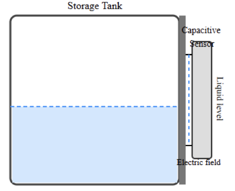
Level Sensors
Level sensors register the height or volume of solids and fluids in reservoirs, silos, and tanks.
They find application in the mining sector as well as in chemical storage. Also in food processing and water purification. Contact or non-contact forms of level sensors exist.
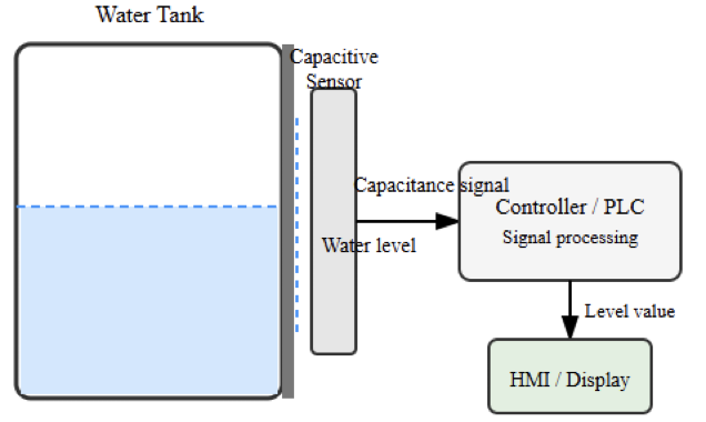
Float switches and capacitive probes, which physically contact the substance being measured, are among contact-level sensors.
Wave reflection methods let non-contact level sensors, like radar and ultrasonic sensors, measure distance.
Because of their capacity to function precisely under harsh temperature, pressure, and vapor circumstances, radar level sensors are rather well-known in current industrial factories.
Material type, tank shape, and environmental conditions all influence the selection of the right level sensor.
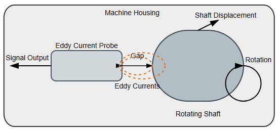
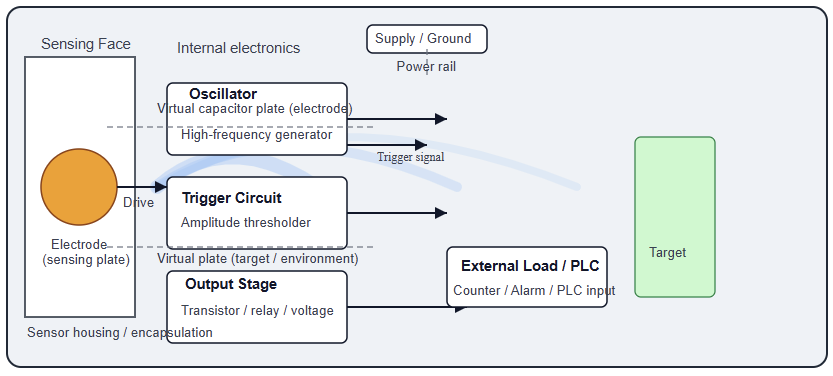
Proximity and Position Sensors
Detecting the presence or absence or position of objects in industrial automation systems depends on these types of sensors.
Conveyor systems and robotic arms all depend on them. Plus, as machine tools and packaging equipment.
In addition, inductive and capacitive are among the most used. Last but not least, photoelectric and ultrasonic sensors are in the list.
Utilizing electromagnetic fields, inductive proximity sensors identify metallic objects. These sensors are very resistant to vibration.
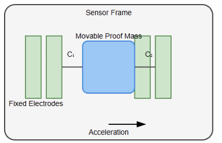
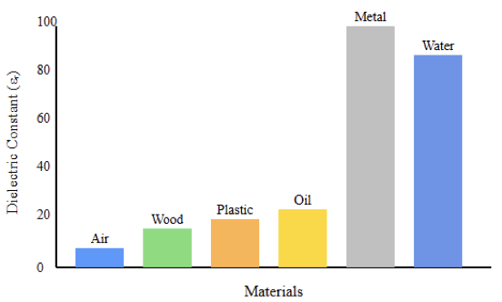
They do so with dust and oil as well. Capacitive proximity sensors can detect both metallic and non-metallic objects. It may include liquids and plastics
Long sensing ranges and quick reaction times characterize photoelectric sensors. They do so by using light beams to detect object presence.
In motion control systems, position sensors offer exact displacement readings. A good example is linear variable differential transformers (LVDTs).
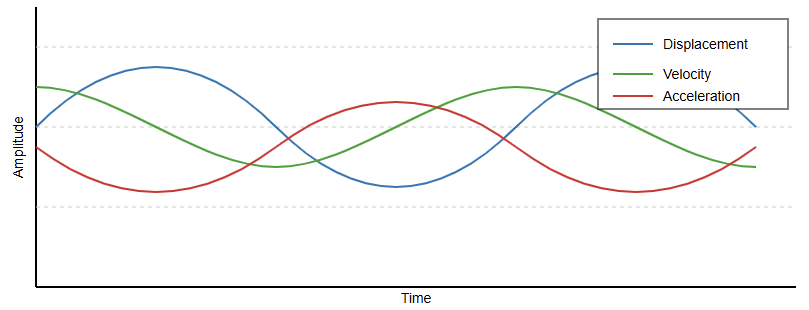
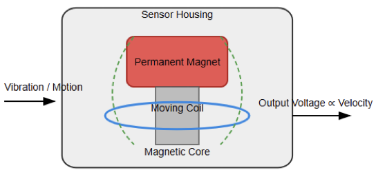
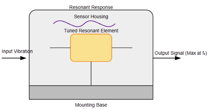
Velocity and Motion Sensors
Rotational or linear motion in motors, conveyors, and spinning equipment is tracked by speed and motion sensors.
Feedback control, predictive maintenance, and safety systems all depend on these sensors.
Most often found speed sensors in industrial situations are encoders and tachometers. High-resolution location and speed information from optical encoders results from light patterns that produce pulses mirroring movement.
Magnetic encoders resist difficult situations and pollution more so than their counterparts.
Often used in motor control applications, tachometers measure rotational speed directly. Motion sensors allow for early intervention by detecting aberrant operating conditions like overspeed or mechanical wear.
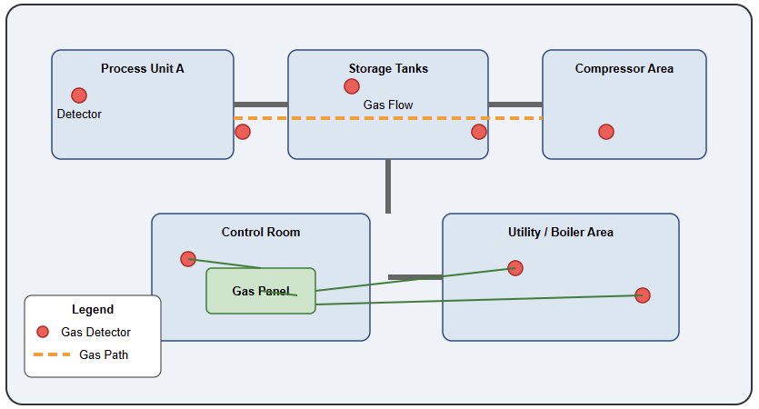
Gas and Chemical Sensors
The procedure of ensuring process control and environmental compliance depends on gas and chemical sensors.
Plus, ensuring the safety of professional personnel. Plants like chemical plants and laboratories use them extensively.
Also, mining projects depend on these sensors. Common gases like oxygen and carbon monoxide are detected by these sensors. Without forgetting hydrogen sulfide, volatile organic chemicals are in the list.
Offering great sensitivity and selectivity, electrochemical gas sensors produce a current depending on gas concentration.
Frequently used for hydrocarbon detection, infrared gas sensors measure the gas absorption of infrared light.
When exposed to particular gases, semiconductor gas sensors alter their electrical resistance.
The target gas kind, concentration range, and environmental conditions determine the choice of the right gas sensor.

Vision and Optical Sensors
For inspection, identification, and quality control, modern industrial automation is progressively employing vision and optical sensors.
Industrial cameras, laser sensors, and color sensors all fall under these. They allow dimensional measurement, barcode reading, and defect detection, among other operations.
High-speed analysis of goods using machine vision systems involves cameras, illumination, and picture processing programs.
Laser sensors provide exact distance and thickness readings even for little or fast-moving items.
Improved product quality and less waste in automated manufacturing lines depend mostly on optical sensors.

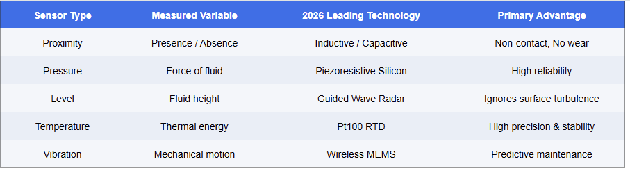
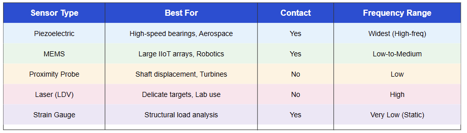
Sensor Comparison Table
This table sorts conventional industrial sensors by the measured variable, dominating technology, and primary advantage.
It underlines how every sensor type is designed for certain uses to increase dependability, accuracy, and predictive maintenance in industrial systems: non-contact detection, precise pressure measuring, steady temperature sensing, or vibration monitoring, for instance.
Rise of IO-Link and Wireless Sensing
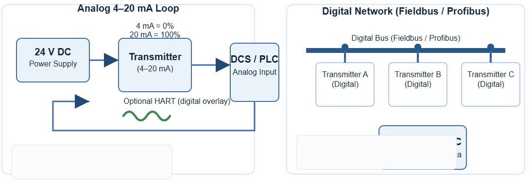
The movement from basic analog signals (4-20mA) toward IO-Link communication is a major trend now.
This digital protocol lets sensors share diagnostic data internal temperature and operating hours in addition to a measurement.
Moreover, wireless sensors have reduced the requirement for costly cabling in big projects. It enables the quick deployment of “smart nodes” in previously inaccessible locations.
Conclusion
The categorization of industrial sensors and their measurement techniques was discussed in this study.
Furthermore, the article details their real-world applications in several industrial contexts. Modern automation and control systems rely on industrial sensors. This lets machines and operations run safely, effectively, and intelligently.
Sensors offer important information for decision-making and control. From gauging fundamental factors like pressure and temperature to facilitating sophisticated vision-based inspection.
Sensor technologies keep developing in accuracy, lifetime, and communication features as data-driven industrial settings become more connected. Right sensor selection and use directly affect system performance, reliability, and operating expense.
FAQs
What are industrial sensors?
Devices that sense physical or chemical conditions like presence and temperature, and translate them into electrical signals for control or monitoring. It also deals with pressure.
What major sensor types are there?
Common examples include visual sensors and vibrations. It also includes flow, pressure, temperature, and proximity.
How does a proximity sensor operate?
Usually employing inductive or capacitive technology, detects object presence or lack without bodily contact.
How in business do temperature sensors operate?
They determine heat levels using thermocouples. RTDs and infrared sensors are also employed.
Why should pressure sensors be utilized?
To keep an eye on the force applied by gases or liquids in systems such as pneumatics or hydraulics.
For what purpose are flow sensors utilized?
They determine how fast liquids or gases flow through pipes.
For what is a vibration sensor for?
Finds mechanical vibrations to help to maintain and monitor the condition.
What are vision sensors?
For inspection, barcode reading, and component guiding, they employ image processing and cameras.
Why should one select non-contact sensors?
They help to cut down on wear and shield from interference from hostile surroundings.
Can sensors measure multiple materials?
Yes, inductive sensors, for example, detect metals; capacitive sensors detect both metals and non- metals.