If you’re just starting with PLC programming, one of the most frustrating moments is when you load your ladder logic and nothing happens.
The motor doesn’t start, the light doesn’t switch on, and the process refuses to move. Instead, there’s only silence—the output is dead.
This experience is common for engineers, technicians, and students alike. Ladder logic may look straightforward in theory, but in real applications, even small mistakes can bring an entire system to a stop.
In this article, we’ll go through the most common reasons why ladder logic fails and explain practical ways to solve these issues.
Ladder Logic Not Working-Common Errors
This section explains some of the common errors (mistakes) that could lead ladder logic not working
Missing latching logic
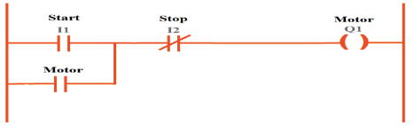
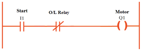
One common mistake is forgetting to latch outputs. Take a start/stop motor circuit.
You press Start, the motor runs. You release Start, the motor should keep running. If you forget the latch, the motor stops immediately when you release the button.

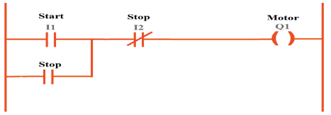
This is not a wiring or hardware problem. It is pure ladder logic. The fix is simple: add a sealing contact (the motor output itself) in parallel with the start button.

Scan cycle misunderstandings
A PLC reads inputs, executes logic, and then updates outputs. This cycle repeats many times per second. If you misunderstand this, you may create rungs that never execute as expected.
For example, if you use a “one-shot” instruction but the input changes faster than the scan cycle, you may miss the pulse.
Or, if you put logic in the wrong program block (like an initialization block that runs once), the rung will never run again.
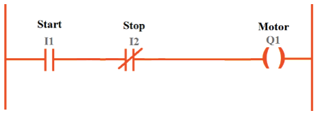
Misuse of normally open vs. normally closed
In ladder logic, you can use NO (normally open) and NC (normally closed) contacts. If you confuse them, your logic may always stay false or always stay true. This happens often with push buttons.

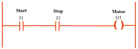
Many stop buttons are wired as normally closed, so if you code them as NO, the rung never makes sense. Always confirm how the device is wired before choosing NO or NC in the software.
Wrong addressing
Addressing is one of the easiest mistakes to make. You may think you are controlling Output 0.1, but in reality, you wrote the logic for Output 0.2.
This happens a lot with big PLCs that have many modules. The difference between I:0/1 and I:1/1 in Allen-Bradley, or between I0.0 and I1.0 in Siemens, can break your code. Always double-check that your ladder logic addresses match the actual wiring diagram.
The PLC is in the wrong mode
This is the most basic issue. Many times, the ladder program looks fine, but the PLC itself is not even running. PLCs usually have modes: Program, Run, and sometimes Remote.
- In Program mode, the controller is not executing the logic. It just waits for edits.
- In Run mode, the controller executes the logic and updates the outputs.
- In Remote mode, you can download new code while still running, depending on the brand.
If your outputs are not turning on, first check the status LEDs on the PLC. Most brands like Siemens, Allen-Bradley, or Mitsubishi have a small “RUN” light. If it is OFF, your ladder logic will do nothing.
Inputs are not true
Ladder logic is based on inputs. If the conditions are not met, the rung will never energize the output.
For example, suppose you want to turn on a motor when a start button is pressed. If the button wiring is wrong, the input never becomes true. In software, the rung looks fine, but in hardware, the bit is always zero.
How to check
- Look at the input status LEDs on the PLC. If the button is pressed and the LED does not light, there is a wiring problem.
- In the PLC software, check the input table. If the bit is not changing, the ladder logic cannot work.
Common mistakes with inputs
- Wrong wiring (NO vs. NC contact confusion).
- Sensor powered with the wrong voltage.
- Loose or broken cable.
- Forgetting to enable the sensor in the field device.
Outputs not wired correctly
Sometimes the ladder logic energizes the output, but the device in the real world does not move. This usually means the output wiring is wrong.
For instance, the rung may energize Output Q0.0, but the motor never starts. When you check the PLC, the output LED is lit. That means the logic is correct. The problem is between the PLC and the motor starter.
Typical causes
- Wrong terminal connection.
- No power supply on the output side.
- Blown fuse.
- Output type mismatch (sourcing vs. sinking).
This is like turning on a light switch in your room but forgetting the bulb is burned out. The switch works. The electricity is there. But the output device is dead.
Safety interlocks cutting the output
Modern machines always have safety interlocks. Emergency stops, overload relays, and safety relays can all cut power.
You may think the ladder logic is broken, but in reality, a safety input is keeping the output off.
Example: The rung is true, but the motor contactor never energizes. When you check, you see the overload relay is tripped.
Until you reset it, nothing will work. Safety interlocks override ladder logic. Always check them.
Wrong data types in logic
This is more common with advanced PLC instructions. For example, if you use a timer and mistakenly set the preset with an integer in seconds instead of milliseconds, the timer may seem not to work.
Or if you use a comparison between an integer and a real number, the rung may never go true.
These are not wiring issues. They are programming issues. They require careful review of the instruction set.
Overcomplicated logic
Sometimes, ladder logic does not work simply because it is too complicated. Too many nested contacts, too many parallel rungs, or too many unused bits can make it impossible to debug.
When you simplify the logic, suddenly everything works. This is why good programming style is important. Short, clear rungs are easier to troubleshoot.
PLC communication issues
In larger systems, your output may depend on communication with another device.
For example, a VFD over Modbus. If communication fails, the output never updates, even if the rung is true.
This often looks like a ladder problem, but in reality, it is a network issue. Check communication status bits. Many PLCs give diagnostic tags that tell if the comms are healthy.
Timer and counter misunderstandings
Timers and counters are powerful, but easy to misuse.
- Some people forget that timers reset when power is lost.
- Some forget that counters need a reset rung.
- Some wire conditions in such a way that the timer never accumulates time.
For example, using a TON (on-delay) with a start button can be tricky. If the button is pressed only for a second, the timer never finishes. Always simulate timers and counters step by step.
Wrong PLC hardware configuration
Modern PLC software requires hardware configuration. You must tell the software what modules exist in the rack. If you forget to configure an input module, the addresses may not match.
This makes it look like the logic is broken, but in fact, the software has no idea the module exists. Always check the hardware configuration before testing logic.
Power supply issues
This one is easy to overlook. The PLC might be powered, but the field devices might not.
- Sensors may need 24V DC but receive none.
- Contactors may need 230V AC but the circuit breaker is off.
- Output cards may require a separate external supply.
This is like turning on your TV, but forgetting the cable box has no power. The TV works fine. The source does not.
Lack of documentation
Sometimes, the problem is not the ladder logic itself, but the lack of comments, labels, and descriptions.
When you return to your program after a week, you may not remember which input does what.
Without documentation, troubleshooting becomes guesswork. Good practice is to always label your rungs, inputs, and outputs. This saves time and reduces errors.
Forgotten downloads
This may seem a smile mistake, but it happens a lot. You make changes to the ladder logic, but you forget to download it to the PLC. So, the machine keeps running the old program.
Always confirm the last download. Some software even shows a timestamp of the active program.
Broken hardware
Finally, sometimes the problem is not logic, wiring, or configuration. Sometimes, the hardware itself is bad.
- A burned output relay.
- A damaged input channel.
- A failed sensor.
If everything looks right in logic and wiring, swap the module or device.
How to Troubleshoot Ladder Logic
Now that we have seen common causes, let’s talk about a process for troubleshooting.
- Check the PLC mode. Is it in Run?
- Check inputs. Are the LEDs lighting when you activate devices?
- Check outputs. Do the LEDs turn on when the rung is true?
- Check wiring. Is power reaching the devices?
- Check interlocks. Are safety devices holding the circuit open?
- Check addresses. Do they match the wiring diagram?
- Check program blocks. Is the logic in the right section?
- Check documentation. Are tags labeled correctly?
With this step-by-step approach, you can usually find the problem quickly.
Key Takeaways: Ladder Logic Not Working – Common Reasons
The present article went through the most common reasons why ladder logic fails. Furthermore, it explained practical ways to solve these issues.
From this discussion be seen clear that the Ladder logic is powerful, but also very sensitive.
One small mistake can make the whole system stop. When your program does not work, do not panic.
Almost always, the cause is one of the issues we discussed: wrong mode, bad wiring, incorrect addresses, safety interlocks, or missing latches.
Take it step by step. Use the LEDs, the software watch tables, and the wiring diagram.
Remember that even experienced engineers make these mistakes. The key is patience and a clear process. With practice, you will troubleshoot faster and with more confidence.
FAQ: Why Ladder Logic Not Working
Why doesn’t my ladder logic program run at all?
Check power supply (wiring, fuses, breakers, and any UPS). Another potential issue: the PLC isn’t actually loaded with the latest program or is in the wrong mode—ensure it’s in Run mode, not Program or Stop.
Why aren’t the inputs or outputs responding correctly?
It could be wiring issues (disconnected, or damaged cables); Power or configurationproblems: ensure I/O modules are properly configured in SW; Faulty modules or devices (failed sensors, damaged I/O modules, or worn components).
Could the problem be with communication?
Yes. Communication breakdowns—like IP mismatches, protocol errors, or bad cabling—can halt logic execution that depends on external devices.
Can logic or programming mistakes cause the system to fail?
Definitely. Common issues include sequencing errors, logic faults, or addressingmistakes in the ladder diagram.
What about power instability or environmental factors?
Voltage fluctuations, poor grounding, EMI, or even overheating can affect PLC stability.
Keep environments clean and controlled; protect against dust, heat, moisture, and other extremes.
What if I suspect hardware failure?
Try to debug you program in simulation mode, define some auxiliary variable and see if the outputs are updated accordingly.
