What is a Solenoid Valve in Automation?

In modern automation, machines rarely operate passively, they need to move, react, and control their environment efficiently.

Whether it’s regulating the flow of liquids or gases, an essential component manages this task with precision and reliability: the solenoid valve. 

What is a Solenoid Valve?

A solenoid valve is an electromechanical device designed to convert electrical signals into a mechanical action.

This action, in turn, opens or closes a valve to control the movement of fluids within a system.

Solenoid valves are indispensable in automated processes because they deliver a combination of precision, speed, and reliability that manual valves cannot match. 

In this article, we will learn what a solenoid valve is, how it operates, its types, advantages, and applications. 

What is a Solenoid Valve in Automation?

Components of a Solenoid Valve?

A solenoid valve is essentially a combination of two key components:

  • The Solenoid: This is an electromagnet that generates a magnetic field when energized.
  • The Valve Body: This houses the mechanical components responsible for opening or closing the fluid path.

The solenoid consists of a coil of wire wound around a ferromagnetic core. Within the core, a plunger or piston made of ferromagnetic material moves in response to the magnetic field. 

When electricity passes through the coil, a magnetic field is generated. This magnetic field pulls the plunger, which in turn either opens or closes the valve’s orifice, regulating fluid flow.

Mathematically, the magnetic force   acting on the plunger can be expressed as:

Where:

This equation shows that the plunger’s movement depends on the coil current and the geometry of the magnetic circuit.

How a Solenoid Valve Works

The operation of a solenoid valve is straightforward yet remarkably effective. Its functionality can be broken down into four stages:

De-energized State:

In this default state, a spring holds the plunger in position. In a normally closed (NC) valve, the plunger blocks the fluid path, preventing flow.

In a normally open (NO) valve, the plunger allows fluid to flow freely without electrical input.

Energized State:

When an electrical current flows through the solenoid coil, a magnetic field form. This field exerts a force on the plunger, moving it against the spring’s resistance.

Valve Actuation:

The plunger’s movement either opens or closes the valve’s orifice. This simple mechanical action precisely controls the fluid or gas flow.

Return to Default:

Once the electrical signal stops, the magnetic field disappears. The spring then pushes the plunger back to its original position, returning the valve to its de-energized state.


    The entire process takes milliseconds, enabling high-speed and highly accurate control, crucial in modern automation systems.

    Key Components of a Solenoid Valve

    A solenoid valve contains multiple components working in concert:

    Valve Body

    The main housing of the valve, constructed from brass, stainless steel, or plastic. It contains the orifice, ports, and internal passages.

    Solenoid Coil

    The electromagnet generating the magnetic field to move the plunger.

    Plunger (or Piston)

    A movable component that opens or closes the valve. Its material is usually ferromagnetic.

    Spring

    Provides the restoring force to return the plunger to its default position when the coil is de-energized.

    Orifice

    The opening in the valve that the plunger covers or uncovers to control fluid flow.

    Ports

    The inlet and outlet connections for fluid or gas. The number of ports defines the valve configuration (e.g., 2-way, 3-way).

    Types of Solenoid Valves in Automation

    Solenoid valves come in several configurations, chosen according to specific application needs.

    By Operating Principle

    Direct-Acting Valves

    The solenoid directly opens or closes the valve. These are simple, fast, and ideal for low pressure and low flow rate applications. No fluid pressure difference is required to operate the valve.

    Pilot-Operated Valves

    A small solenoid controls a pilot valve, which uses the system’s fluid pressure to operate a larger main valve. These are suited for high flow rate and high-pressure systems and are more energy-efficient.

    Semi-Direct Acting Valves

    This type combines features of direct and pilot-operated valves. They can operate at low or zero pressure while handling moderate-to-high flow rates.

    Equation for Fluid Flow Through a Solenoid Valve:

    By Flow Path (Number of Ports)

    2/2-Way Valves

    Two ports and two positions, acting as a simple ON/OFF switch.

    3/2-Way Valves

    Three ports, two positions. Can direct flow to multiple paths or vent pressure, commonly used for single-acting cylinders.

    4/2, 4/3, and 5/2 Valves

    More complex configurations to control double-acting cylinders or sophisticated fluid paths.

    By Default State

    Normally Closed (NC)

    Closed when de-energized; opens when powered. Most common type.

    Normally Open (NO)

    Open when de-energized; closes when powered. Useful in fail-safe applications where uninterrupted flow is critical.

    Advantages of Solenoid Valves in Automation

    Solenoid valves bring numerous benefits to automated systems:

    Fast Response Time

    Switching occurs in milliseconds, essential for precise and high-speed operations.

    Remote Control

    Electrically actuated, allowing centralized or remote operation, ideal for inaccessible or hazardous areas.

    Reliability and Durability

    Few moving parts ensure a long service life, even in harsh industrial environments.

    Compact Design

    Small footprint allows installation in tight spaces and manifold mounting.

    Low Energy Consumption

    Modern solenoids are highly efficient, reducing operational costs compared to other actuators.

    Automation of Fluid Control

    Replaces manual valves, improving efficiency, safety, and productivity.

    Applications of Solenoid Valves in Automation

    Solenoid valves are widely used in multiple industries:

    Pneumatic Systems

    Control compressed air to operate actuators, cylinders, and tools.

    Hydraulic Systems

    Direct hydraulic fluid to control heavy machinery in manufacturing and construction.

    Water Treatment

    Manage water and chemical flow for precise dosing and processing.

    Food and Beverage Industry

    Control ingredient flow and cleaning fluids in automated dispensing and bottling systems.

    Medical Equipment

    Regulate gases and fluids in devices such as ventilators and dialysis machines.

    Automated Sprinkler Systems

    Efficient irrigation by controlling water distribution across multiple zones.

    Industrial Processes

    Used for mixing, dosing, and distributing fluids in pilot plants and full-scale production lines.

    Key Takeaway: What is a Solenoid Valve?

    In this article, we will learn what a solenoid valve is, how it operates, its types, advantages, and applications.

    Along the way, diagrams and equations will help illustrate the concepts more clearly, providing both practical and theoretical insight.

    The solenoid valve is a cornerstone component in automation. It creates a seamless link between electrical signals and fluid power, enabling precise and reliable control.

    From simple on/off functions to complex directional control, solenoid valves are versatile, fast, and efficient.

    As automation technologies evolve, the solenoid valve continues to play a critical role in industrial control systems, offering reliability, compactness, and energy efficiency.

    Its simple operating principle combined with robust performance makes it indispensable for modern industrial processes.

    FAQ: What is a Solenoid Valve?

    What is the main difference between normally open and normally closed solenoid valves?

    Normally open valves allow flow when de-energized, while normally closed valves block flow until energized.

    Can solenoid valves handle high pressures?

    Yes, especially pilot-operated and semi-direct acting valves designed for high-pressure systems.

    How fast can a solenoid valve respond?

    Many solenoid valves switch in milliseconds, suitable for high-speed automation.

    Are solenoid valves suitable for hazardous environments?

    Yes, especially explosion-proof or stainless-steel designs for corrosive or flammable environments.

    Can they be used in both liquids and gases?

    Absolutely. The design may vary slightly depending on the medium, but solenoid valves can handle air, water, oil, and other fluids.

    How to Write Your First PLC Program in Siemens TIA Portal

    A Programmable Logic Controller (PLC) is a specialized digital industrial computer. It has been designed and ruggedized to reliably handle automation and control tasks in industrial environments where dust, vibration, heat, and electrical noise are present.

    It constantly monitors the state of connected input devices, makes logical decisions using a custom user-defined program, then updates the state of output devices.  

    This article introduces the fundamental steps for programming a PLC using Totally Integrated Automation Portal (TIA Portal) software from Siemens. It explains the importance of TIA Portal as a development tool. 

    Then, it describes how to configure the software, and shows step-by-step instructions to create a program using ladder logic (LD).

    Finally, it walks through the process of downloading the program into a real PLC and verifying its operation.

    The Siemens TIA Portal

    The TIA Portal is Siemens’ flagship engineering framework. It is an all-in-one software suite that provides a single, unified platform for programming, configuring, and commissioning automation systems.

    Instead of using multiple separate tools, TIA Portal integrates all essential automation engineering functions into one environment, making it easier for engineers to work efficiently.

    Within TIA Portal, different engineering tools coexist in harmony. For PLCs, it uses STEP 7, which is the programming environment. For operator interfaces such as Human-Machine Interfaces (HMIs), it uses WinCC

    For drive systems and motion control, it integrates Startdrive. This tight integration means that an engineer can configure hardware, program logic, and design operator panels in a consistent workflow.

    Why choose TIA Portal?

    TIA Portal is widely chosen because it significantly streamlines the entire engineering process.

    It allows engineers to reduce development time, eliminate redundancies, and increase consistency across projects. 

    The intuitive user interface, powerful libraries, and drag-and-drop features help make programming accessible, even to beginners.

    Another advantage is its flexibility in supporting multiple international programming languages defined by IEC 61131-3. These include:

    • Ladder Logic (LAD) – graphical, easy to understand, resembles electrical circuits.
    • Function Block Diagram (FBD) – suited for process control and data flow.
    • Structured Control Language (SCL) – text-based, similar to high-level programming languages.

    This versatility makes TIA Portal a preferred choice for both newcomers and experienced engineers working on complex industrial automation projects.

    The Best PLC Simulation Software in 2025

    How to Write Your First PLC Program in Siemens TIA Portal

    Step 1: Planning your first program

    Define your application

    Before any code is written, the very first step in PLC programming is planning. A well-structured plan ensures that the logic is clear, the requirements are met, and unnecessary mistakes are avoided.

    Clearly define what you want the program to achieve. For beginners, it is best to start with a simple application that illustrates basic control principles.

    Example application: A motor start/stop circuit using pushbuttons and an indicator lamp.

    Requirements:

    • A start pushbutton should turn the motor ON.
    • A stop pushbutton should turn the motor OFF.
    • The motor should remain running (latched) even after the start pushbutton is released.
    • A status light should indicate when the motor is running.

    This simple yet practical example teaches the concept of latching circuits, which is fundamental in PLC programming.

    Define your inputs and outputs (I/O)

    Every PLC program is connected to real-world devices. These devices are classified as inputs (information coming into the PLC) and outputs (commands sent from the PLC).

    To avoid confusion, each device must be clearly listed, assigned a descriptive tag name, and mapped to a data type.

    DeviceTypeData TypeDescription
    Start_PBInputBOOLActivated when the start pushbutton is pressed
    Stop_PBInputBOOLActivated when the stop pushbutton is pressed
    Motor_RunningOutputBOOLControls the motor starter coil
    Motor_Light_ONOutputBOOLTurns on the lamp when the motor is running

    Step 2: Creating a new project

    Launch TIA Portal

    Open TIA Portal software from your desktop or start menu. Once the program loads, you will see the start screen with several options.

    Create a new project

    1. On the start screen, click “Create new project”.
    2. Enter a project name, such as My_First_PLC_Program.
    3. Choose a file path to save the project.
    4. Click “Create” to confirm.

    Configure a device

    1. On the “First steps” page, click “Configure a device”.
    2. Select “Add new device”.
    3. Expand the Controllers folder.
    4. Choose from the SIMATIC S7-1200 or S7-1500 series. (The S7-1200 is highly recommended for beginners due to its affordability and flexibility.)
    5. Select the exact CPU model that matches your hardware.
    6. Click “Add” to include it in the project.

    Step 3: Hardware configuration

    Assigning IP address

    1. Once the CPU is added, the device view opens.
    2. In the properties window at the bottom, select “PROFINET interface”.
    3. Under Ethernet addresses, enter an IP address for the PLC, e.g., 192.168.0.1.
    4. This address will be used later to connect the PC with the PLC.

    Configuring I/O addresses

    1. In the same properties, go to “I/O addresses”.
    2. These addresses are where the PLC program links to actual hardware inputs and outputs.
    3. By default, for an S7-1200, inputs often start at %I0.0 and outputs at %Q0.0.
    4. Verify or adjust these addresses to match your application.

    Step 4: Creating PLC tags

    Open the default tag table

    1. In the project tree, expand “PLC tags”.
    2. Double-click “Default tag table”.
    3. A table opens where you can create tags for your I/O devices.

    Add your tags

    1. Add a new tag for each I/O defined in the plan.
    2. Assign tag names and data types (all BOOL in this example).
    3. The software automatically assigns addresses, but they can be changed.
    Tag NameData TypeAddress
    Start_PBBOOL%I0.0
    Stop_PBBOOL%I0.1
    Motor_RunningBOOL%Q0.0
    Motor_Light_ONBOOL%Q0.1

    Step 5: Writing the Ladder Logic program

    Open the Main Program Block (OB1)

    1. Expand “Program blocks” in the project tree.
    2. Double-click “Main [OB1]”.
    3. This block runs cyclically and forms the backbone of the program.

    Program Network 1: Start/Stop logic

    This network contains the motor latching circuit.

    1. From the Basic Instructions panel, drag a Normally Open Contact (NO).
    2. Place another NO contact in parallel with it.
    3. Add a Normally Closed Contact (NC) in series.
    4. Place a Coil (=) at the end.

    Wiring:

    • Assign Start_PB to the first NO contact.
    • Assign Motor_Running to the parallel NO contact.
    • Assign Stop_PB to the NC contact.
    • Assign Motor_Running to the coil.

    Logic: If Start_PB is pressed OR Motor_Running is already latched, AND Stop_PB is not pressed, then Motor_Running stays ON.

    Program Network 2: Status light

    This network turns on the lamp when the motor is running.

    1. Insert an NO contact.
    2. Insert a Coil.
    3. Assign Motor_Running to the contact.
    4. Assign Motor_Light_ON to the coil.

    Logic: If Motor_Running = TRUE, then Motor_Light_ON = TRUE.

    Step 6: Simulating the program

    Start the simulation

    1. Save the project.
    2. Select the PLC in the project tree.
    3. Click “Start simulation”.
    4. Confirm the pop-up window.
    5. The program compiles and loads into the virtual PLC.
    6. Select “Start all” to begin simulation.

    Test with a watch table

    1. Expand “PLC tags”“Show all tags”.
    2. Open the watch table.
    3. Modify the Start_PB tag to True. Observe Motor_Running and Motor_Light_ON.
    4. Return Start_PB to False – the motor should remain latched.
    5. Change Stop_PB to True – the motor and lamp should turn off.

    Step 7: Downloading to a physical PLC

    Establish communication

    1. Connect PC to PLC via Ethernet.
    2. In TIA Portal, click “Go online”.
    3. Select your network adapter.
    4. Search for accessible devices.
    5. Assign an IP if required.

    Download the program

    1. Right-click CPU → “Download to device”.
    2. Select hardware + software.
    3. Confirm settings → Load.
    4. After download, choose “Start all modules”.
    5. The PLC enters RUN mode.

    Monitor and debug

    1. Open OB1.
    2. Enable Monitoring on/off.
    3. Observe green power flow lines.
    4. Use pushbuttons to test and verify outputs.

    Key Takeaways: How to Write Your First PLC Program in Siemens TIA Portal

    You have successfully gone through the process of planning, programming, simulating, and downloading a PLC program using Siemens TIA Portal.

    This motor start/stop application demonstrates a core concept: latching circuits, which are the foundation of industrial automation.

    By mastering this workflow, you now have a solid base to explore more advanced topics such as timers, counters, data blocks, and structured programming. Always remember to:

    • Plan your project carefully before coding.
    • Use descriptive tag names for clarity.
    • Simulate and test your program thoroughly before deploying.

    With experience, you will be able to create structured, scalable PLC applications that control entire production systems.

    FAQ: How to Write Your First PLC Program in Siemens TIA Portal

    What is TIA Portal used for?

    TIA Portal is Siemens’ engineering software used to program PLCs, configure HMIs, commission drives, and manage industrial networks within one integrated environment.

    Which PLCs can be programmed with TIA Portal?

    TIA Portal mainly supports Siemens PLCs such as the S7-1200, S7-1500, S7-300, and S7-400, along with related devices.

    Is ladder logic the only programming language available?

    No. TIA Portal supports LAD, FBD, SCL, and also function charts, giving engineers flexibility in programming style.

    Do I need real hardware to practice?

    Not necessarily. TIA Portal includes PLCSIM, a simulation tool that allows you to test logic without a physical PLC.

    How do I connect my PLC to TIA Portal?

    You typically connect via Ethernet, assign an IP address, and then use the “Go online” function to establish communication.

    Can I program safety PLCs with TIA Portal?

    Yes, Siemens offers Fail-Safe CPUs that can be programmed in TIA Portal with additional safety libraries.

      What is Scan Time in PLCs?

      A Programmable Logic Controller (PLC) is a specialized computer used in industrial applications. It is designed specifically to survive in harsh industrial environments and to control machines and processes reliably. 

      The PLC works as the brain of automation, ensuring that every input is monitored and every output is controlled according to programmed logic.

      The PLC needs to work quickly because industrial processes often demand immediate and precise actions.

      To achieve this, the PLC performs a continuous loop of operations without pause. This loop is called a scan cycle, and it repeats constantly as long as the PLC is powered and in run mode. 

      The time it takes for one full loop to complete is known as the scan time. Even though the scan time is often measured in milliseconds, it makes a huge difference in how responsive and accurate a system can be.

      This article will explain in detail what scan time is. It will also cover why scan time matters, what factors affect it, and how engineers can optimize it for better performance.

      The Scan Cycle: A Three-Step Process

      The scan cycle is the heart of a PLC’s work. It is what allows the controller to continuously read inputs, make decisions, and update outputs. The process involves three main steps that repeat over and over.

      PLC scan cycle

      Input Scan

      The PLC first reads the status of all input devices connected to it. These devices may include sensors, push buttons, switches, limit switches, proximity sensors, or any other type of input. 

      The PLC checks each device almost at the same instant and takes a “snapshot” of all inputs.

      It saves this information in its memory, usually in an internal area called the Input Image Table or Process Image Input (PII).

      The stored data is then used throughout the rest of the scan cycle. This method prevents errors caused by inputs changing during program execution.

      For example, if a button is pressed and released very quickly, the PLC will still register its state during the snapshot, ensuring consistency.

      Program Execution

      Next, the PLC runs the user program that was written and downloaded by the engineer.

      This program is often written in ladder logic, structured text, or function block diagram depending on the application. 

      The CPU processes the instructions step by step in the order they are arranged. During this stage, the PLC does not read the real inputs directly. Instead, it uses the values stored in the Input Image Table. 

      This design ensures stable decision-making without interference from rapidly changing inputs.

      Based on these values, the PLC updates a different section of memory called the Output Image Table or Process Image Output (PIO).

      For example, the program might check if a start button is pressed and a safety sensor is clear.

      If both conditions are true, the PLC sets a coil in the Output Image Table that will later energize a motor starter.

      Output Scan

      Finally, the PLC updates the output devices. It takes the data from the Output Image Table and sends the actual signals to actuators, relays, solenoids, indicator lamps, alarms, or motor drives.

      This ensures that the physical world reflects the logic decisions made in the program.

      For example, if the Output Image Table indicates that a motor coil should be energized, the PLC will activate the corresponding output terminal and power the motor.

      After completing these three steps, the cycle repeats immediately. Modern PLCs can complete thousands of these cycles per second, but the exact speed depends on the PLC model and program size.

      Why Scan Time is Important

      Scan time is a critical performance measure because it directly affects how the PLC controls a system.

      A small change in scan time can make a big difference in system responsiveness and reliability.

      System Responsiveness

      A shorter scan time means the PLC can react faster to changes in inputs. This is crucial for high-speed machinery such as packaging lines, bottling plants, or pick-and-place robots.

      If the scan time is too slow, the PLC might not respond in time, leading to missed cycles or mechanical faults.

      Precision Control

      Many processes need precise and continuous adjustments. Examples include motion control systems in robotics, dosing in chemical plants, or temperature control in furnaces.

      A shorter scan time allows the PLC to make more frequent updates and corrections, improving accuracy.

      Performance and Safety

      In safety-critical applications such as emergency stops or conveyor belt protection, a slow scan time can be dangerous.

      Even a delay of a few milliseconds could prevent an emergency stop from engaging quickly enough.

      Monitoring and managing scan time is therefore essential for operator safety.

      Avoiding Missed Events

      Some input signals, such as pulses from an encoder or a high-speed sensor, can occur much faster than the scan time.

      If the PLC is not fast enough, it can miss these pulses completely. This can cause incorrect counts, positioning errors, or faulty operations.

      Factors That Influence Scan Time

      Many things can affect how fast a PLC completes its scan cycle. Understanding these factors helps in both troubleshooting and designing efficient programs.

      Program Complexity

      A simple program with a few instructions runs quickly, while a long and complex program with many nested conditions, loops, or calculations takes more time.

      For instance, a program that includes PID control, data logging, or advanced motion functions will increase the scan time compared to a basic on/off control program.

      Number of I/O Devices

      Each input and output adds to the scan time because the PLC must check or update every point.

      A system with hundreds of I/O points will naturally take longer than a system with just a handful.

      CPU Performance

      Just like in a computer, the processor speed of the PLC matters. A modern high-speed PLC can execute instructions in microseconds, while older models may take much longer.

      Communication Overhead

      Many PLCs communicate with external devices such as HMIs, SCADA systems, robots, or other controllers.

      The time spent exchanging data can add to the scan time, especially if there is heavy network traffic.

      Special Instructions

      Not all instructions are equal. Floating-point calculations, trigonometric functions, or data conversions require more processing time than simple Boolean logic.

      System Health and Diagnostics

      The PLC also performs background tasks like memory checks, fault diagnostics, and error handling. These small tasks, though necessary, slightly increase the total scan time.

      How to Optimize Scan Time

      In many cases, the standard scan time provided by the PLC is enough for normal operation.

      However, for high-speed or time-critical applications, engineers may need to optimize.

      Use Subroutines

      Organize your program into subroutines. You can call or skip sections of logic depending on need.

      This prevents the PLC from wasting time on code that is not always required, reducing the average scan time.

      Optimize Logic

      Write programs as efficiently as possible. Avoid unnecessary instructions, repeated calculations, or redundant rungs.

      Place the most likely conditions at the start of each rung so that the PLC can skip evaluating the rest if unnecessary.

      Use Integers over Floats

      Where possible, use integer data types for calculations. Integer math is much faster than floating-point math, especially on lower-end PLCs.

      Upgrade Hardware

      If scan time remains too long, upgrading to a modern PLC with a faster processor or more memory may be the best solution.

      This is often necessary in applications involving robotics, high-speed packaging, or CNC systems.

      Use Interrupts for High Speed

      Some tasks cannot wait for the regular scan cycle. For these, PLCs provide interrupts, special events that pause the normal program and immediately execute critical logic.

      Interrupts are commonly used for high-speed counters or emergency stop inputs.

      Avoid Unnecessary Tasks

      Minimize communication and background tasks that happen every scan. For example, data logging can be set to occur every second instead of every cycle. This reduces unnecessary load.

      Key Takeaways: What is Scan Time in PLCs?

      Scan time is a simple concept with very big implications in industrial automation. It represents the time a PLC takes to perform one complete cycle of operations: reading inputs, executing the program, and writing outputs.

      Even though scan times are often very short, they determine how fast and accurately a system responds.

      A short scan time is key for fast, precise, and safe control. Many factors affect scan time, including program size, I/O count, CPU speed, and communication load. By understanding these factors and applying optimization techniques, engineers can design more reliable and efficient automation systems.

      In modern industries where milliseconds matter, mastering scan time ensures that machines perform safely, efficiently, and exactly as intended.

      FAQ: What is Scan Time in PLCs?

      What is PLC scan time?

      PLC scan time refers to the duration it takes for a PLC to complete one full cycle of operations: reading inputs, executing the control program, and updating outputs. This cycle is crucial for the PLC to monitor and control industrial processes effectively.

      How long is a typical PLC scan time?

      PLC scan times can vary widely, typically ranging from 1 millisecond to 50 milliseconds, depending on factors such as the complexity of the control program, the number of inputs and outputs, and the processing capabilities of the PLC. 

      What factors affect PLC scan time?

      Several elements can influence the scan time of a PLC:

      • Program Complexity: More complex programs with numerous instructions or loops require more processing time.
      • Number of Inputs and Outputs: A higher count of I/O points increases the time needed to read inputs and update outputs.
      • Processor Speed: Faster processors can execute instructions more quickly, reducing scan time.
      • Communication Overhead: Time spent communicating with external devices or networks adds to the total scan time.
      • Instruction Types: Certain instructions, like floating-point calculations, take longer to execute than simpler ones. 

      Why is scan time important?

      Scan time is critical because it determines how quickly a PLC can respond to changes in the process.

      A shorter scan time allows for faster reaction to input changes, leading to more precise control and improved safety in time-sensitive applications.

      How can I reduce PLC scan time?

      To optimize scan time:

      • Simplify the Program: Reduce unnecessary instructions and optimize logic to streamline execution.
      • Use Efficient Data Types: Opt for integer operations over floating-point calculations where possible.
      • Organize Code with Subroutines: Modularize the program to isolate tasks and reduce the overall scan time.
      • Upgrade Hardware: Consider using a PLC with a faster processor or more memory to handle complex tasks more efficiently.
      • Minimize Communication Delays: Limit the frequency and volume of data exchanges with external devices to reduce overhead. 

      How can I monitor PLC scan time?

      Many PLCs provide diagnostic tools or built-in functions to monitor scan time. By regularly checking this parameter, you can assess the performance of your control system and identify areas for improvement.

      Edge Computing in Industrial Automation

      Industrial automation is changing and factories are becoming smarter. They are using more connected devices than ever before. These devices are not only sensors and machines, but also advanced controllers, cameras, and industrial robots. 

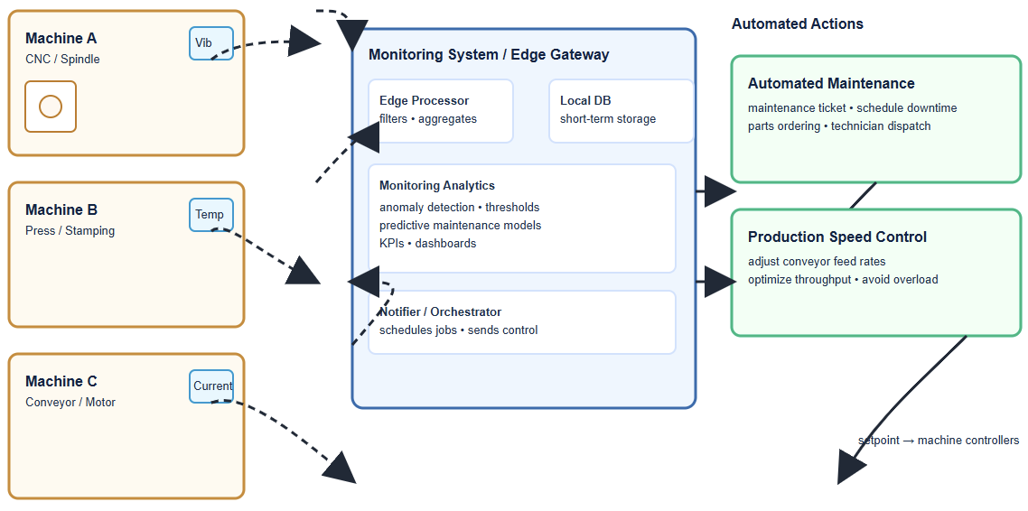
      Each device generates large amounts of valuable data. Edge computing is a key part of this change because it processes data closer to its source.

      This is at the “edge” of the network. In factories, this means the shop floor, production line, or even individual machines. 

      Processing data locally instead of sending it far away creates faster responses, which brings many benefits for industrial automation.

      It reduces delays and improves reliability. It also supports modern applications like predictive maintenance, robotics, and energy efficiency.

      This article explains what edge computing is, its role in industrial automation, benefits, challenges, and finally, its future.

      Evolution from traditional automation → cloud computing → edge computing.

      The shift from cloud to edge

      Traditionally, data from factory sensors was sent to a central data center. This was for storage, processing, and analysis. Engineers would collect data, send it to the cloud, and wait for results.

      But this can cause delays, called latency. Latency is a big problem for real-time automation.

      Even a small delay of a few milliseconds can stop a robot arm from reacting correctly.

      It can cause defects on a fast-moving assembly line. It can even affect safety systems that need instant action.

      Cloud computing also has high costs for bandwidth. Industrial Internet of Things (IIoT) devices may produce gigabytes of data every second. Sending everything to the cloud wastes resources and money.

      Edge computing offers a different approach. It puts processing power near the data source.

      Devices like edge gateways, rugged servers, or intelligent PLCs do the work. These devices are installed directly in factories.

      This local processing reduces latency. It improves responsiveness. It allows for real-time decision-making.

      Operators and machines can act immediately based on local insights. At the same time, only important summaries or trends are sent to the cloud for higher-level use.

      Cloud-Centric vs. Edge-Centric architectures

      Architecture of industrial edge computing

      The architecture of industrial edge computing can be thought of in layers. Each layer has its own role and purpose.

      Device layer

      This is the base layer. It includes all the devices that generate data. Examples are sensors, robots, and programmable logic controllers (PLCs). These devices collect huge amounts of data every second.

      In a smart factory, hundreds of devices may be connected. They measure temperature, vibration, pressure, energy use, or product quality.

      Without processing, this raw data is too large to handle. That is why the next layer is important.

      Edge layer

      This layer is right above the device layer. It contains edge servers and gateways. These process data locally and in real-time.

      They filter out unnecessary or repetitive information. Only critical information is forwarded to the cloud.

      For example, an edge device can check vibration data from a motor. If it detects an unusual pattern, it can send an alert instantly.

      It does not need to wait for cloud approval. This layer is key for low-latency actions.

      Cloud layer

      This is the highest layer. It receives aggregated and analyzed data from the edge layer.

      It is used for long-term storage, big data analytics, and historical insights. It helps with higher-level business decisions.

      Managers can use this information for planning, forecasting, and improving efficiency. While the edge ensures fast responses, the cloud provides the big picture.

      A three-layer architecture diagram: Device Layer → Edge Layer → Cloud Layer.

      Benefits of edge computing

      Low latency and real-time control

      Speed is vital in industrial settings. Edge computing eliminates the delay of sending data to the cloud. Machines can react instantly.

      For example, a robot can stop when a worker enters its zone. A conveyor belt can pause when a defective product is detected. This is crucial for safety-critical systems.

      Optimized bandwidth

      Industrial IoT devices produce massive amounts of data. Sending all this raw data to the cloud consumes bandwidth.

      Edge computing processes data locally. It sends only relevant insights, like alarms or performance summaries, to the cloud. This reduces bandwidth usage and costs significantly.

      Enhanced security

      Processing sensitive data locally keeps it more secure. It reduces the risk of data being intercepted during transit to the cloud.

      Many factories handle confidential production processes. Keeping this information on-site helps with data privacy and compliance with regulations.

      Improved operational efficiency

      Real-time insights on the factory floor help optimize processes. Machines can adjust automatically.

      Operators can make faster decisions. This increases productivity and reduces waste.

      High reliability

      Edge systems can function even when cloud connectivity is lost. This is vital for remote sites or areas with poor internet.

      For example, a mining site or offshore platform can still operate locally. This ensures operational continuity and safety.

      Use cases in industrial automation

      Predictive maintenance

      Sensors on machines monitor performance. Edge devices analyze this data in real-time. They can detect early signs of a potential failure.

      For instance, vibration data may show that a motor bearing is wearing out. This allows maintenance to be scheduled before a breakdown occurs. The result is less downtime and lower costs.

      Automated quality control

      High-speed cameras and sensors inspect products on the assembly line. An edge device processes the images instantly.

      If it sees a defect, it can reject the product in milliseconds. This improves product quality, reduces waste, and maintains consistency.

      Robotics and autonomous systems

      Autonomous robots need to make split-second decisions. They process data from their sensors locally.

      This allows them to navigate safely and perform tasks in real-time. Without edge processing, delays could cause collisions or inefficiency.

      Supply chain optimization

      Edge devices track inventory and monitor vehicles in real-time. For example, smart tags can report stock levels instantly.

      Processing this data on-site allows for immediate adjustments. This helps optimize logistics and respond quickly to disruptions.

      Energy management

      Edge systems can monitor energy usage across a plant. They identify energy-intensive processes.

      They can automatically turn off idle machines or adjust settings to save power. This reduces energy costs and supports sustainability goals.

      Challenges of industrial edge computing

      Integration with legacy systems

      Many factories use older equipment. This equipment was not designed for modern digital architectures.

      Integrating edge solutions with these machines can be complex and expensive. Custom adapters or upgrades may be needed.

      Data management

      Factories generate huge volumes of data. Managing and storing this data locally requires robust infrastructure.

      If not planned well, local systems can become overwhelmed. Companies must design scalable storage and processing solutions.

      Security concerns

      Edge computing increases the number of potential entry points for cyberattacks. Each edge device can be a vulnerability.

      Hackers may target gateways or servers. Strong security protocols and constant monitoring are necessary.

      Skilled workforce

      Managing edge infrastructure needs specialized skills. Workers must understand networking, cybersecurity, and industrial systems.

      Many companies must invest in training or hire new personnel. Without skilled staff, projects may fail.

      Scalability

      Edge solutions must be able to grow with the business. Starting with pilot projects and planning for expansion is important.

      Companies should design architectures that can scale easily without replacing everything.

      The future of industrial edge computing

      Convergence with 5G

      5G networks offer high bandwidth and low latency. They enable seamless machine-to-machine communication.

      With 5G, mobile robots and wireless sensors can exchange data instantly. This will further enhance industrial edge applications and expand flexibility on the factory floor.

      Advancements in AI

      AI models are becoming more powerful and efficient. They can be deployed directly on edge devices.

      This will enable more intelligent and automated decision-making. For example, AI at the edge can predict quality issues, optimize robot movements, or adjust production schedules in real-time.

      Standardization

      Currently, the market has many different solutions. Each vendor provides its own hardware and software.

      Standardization is needed for easier implementation. Open standards will simplify integration, reduce costs, and accelerate adoption of edge computing.

      Key takeaways: Edge Computing in Industrial Automation

      The present article detailed what edge computing is, its role in industrial automation, benefits, challenges, and finally, the future of this edge computing.

      From this discussion, and without hesitation, we can say that edge computing is driving the next industrial revolution.

      It moves data processing closer to the source and reduces latency and improves efficiency. It also enhances security and reliability.

      Furthermore, challenges like legacy system integration and security must be addressed.

      Skilled staff and strong planning are essential. But with careful preparation, the benefits are immense.

      In addition, the future of manufacturing is autonomous and intelligent. Edge computing is a key enabler of this future. It bridges the gap between devices, people, and the cloud. It empowers industries to be faster, smarter, and more sustainable.

      FAQ: Edge Computing in Industrial Automation

      What is edge computing and how is it different from cloud computing?

      Edge computing means processing data close to where it is generated (machines, sensors, etc.), instead of sending everything to a distant cloud. This reduces latency, bandwidth usage, and often improves reliability. 

      Why is low latency important in industrial automation?

      Many industrial tasks require instant or near-instant responses — e.g. safety systems, robotics, real-time quality control.

      Delays (latency) can lead to defects, safety hazards, and inefficiencies. Edge computing helps by processing data locally so decisions happen quickly. 

      What kinds of use cases are there for edge computing in factories?

      Some common ones:

      • Predictive maintenance (monitoring machine health and detecting failures early). 
      • Quality control / visual inspection using computer vision. 
      • Robotics and autonomous systems (robots that need fast sensor feedback). 
      • Supply chain or warehouse optimization (inventory tracking, real-time visibility). 
      • Energy management (monitoring usage, shutting off idle machines, optimizing consumption). 

      What benefits can companies expect from deploying edge computing?

      • Faster response times and real-time control. 
      • Reduced bandwidth costs and lower cloud storage/transfer fees, since not all data is sent offsite. 
      • Enhanced security and data privacy (sensitive data can remain local). 
      • Improved operational resilience (able to operate even with unreliable internet). 
      • Better cost efficiency in the long run, especially when many devices are involved. 

      What are the challenges or drawbacks of edge computing in industrial settings?

      • Integration with legacy systems (older machines not built for modern connectivity) can be difficult. 
      • Limited computing resources on edge devices: less CPU, memory, storage than cloud data centers. 
      • Security risks: each edge device can be a potential attack surface. Maintaining updates, ensuring encryption, securing physical access all matter. 
      • Hardware management and maintenance are more complex when many edge devices are deployed. 
      • Scalability: ensuring solutions grow well without overhauling everything. 

      How does edge computing help with security and compliance?

      Because data can be processed locally, there is less data in transit over external networks.

      That reduces exposure to interception or external threats. It helps with data sovereignty rules, privacy laws, or industry-specific compliance.

      Is internet connectivity still needed? What happens when connectivity fails?

      Yes, connectivity helps for sending aggregated data, updates, or for cloud-based analytics.

      But edge systems are designed to continue functioning even with intermittent or no internet. They carry out local control, safety, and monitoring even when disconnected. 

      What role do AI and machine learning play at the edge?

      AI/ML enable more intelligent analytics, anomaly detection, predictive models, and automation.

      When deployed at the edge, they can act immediately on sensor data. For example, image recognition on defect detection, or anomaly detection in vibrations. 

      How does 5G interact with edge computing?

      5G offers high bandwidth and low latency wireless connectivity. It allows edge devices and sensors to communicate more reliably.

      It enables you to place edge nodes further from wired infrastructure. It also supports mobile or moving devices.

      When is edge computing not the best solution?

      • When latency is not critical and cloud-based solutions are already meeting needs.
      • When the cost of deploying and maintaining many edge devices outweighs the benefits.
      • If infrastructure (power, cooling, environmental protection) is not sufficient for edge hardware.
      • When data volumes aren’t large or when connectivity is reliable and affordable, so that cloud approaches make more sense. (In short: it depends on the use-case.) 

      How should companies plan for scaling edge computing deployments?

      • Start with pilot projects to validate use-cases.
      • Use modular, flexible architectures so you can expand.
      • Ensure hardware, software, and network standardization for interoperability.
      • Plan for device lifecycle: updates, security, maintenance.
      • Monitor total cost of ownership (TCO) including hardware, operations, and staff training. 

      What hardware is needed for edge computing in industrial automation?

      Edge computers, gateways, ruggedized servers, sensors with computing capability, PLCs with more advanced functionality.

      They often need to be durable, able to handle vibration, temperature extremes, dust, etc. Also good networking (wired and/or wireless) and sometimes specialized accelerators (GPUs, TPUs) for AI workloads.

      What standards or interoperability issues exist?

      The market has many vendors, many proprietary systems. Standards like OPC UA, TSN (Time Sensitive Networking), and cross-vendor frameworks are becoming more important. Interoperability helps reduce integration costs

      Ladder logic vs Python for Automation

      Traditionally, automation control was achieved using relay logic, which relied on physical relays wired together to make decisions. Today, this job is handled by Programmable Logic Controllers (PLCs).

      These are specialized industrial computers built for real-time control. PLCs are programmed using specific languages that allow engineers to create control logic. The most famous of these languages is Ladder Logic (LD). 

      It is a graphical way of programming that looks like old relay circuits. This makes it intuitive for electricians and technicians. Another option is Python. Python is a high-level, general-purpose language.

       It was not originally designed for PLCs, but it has become extremely popular thanks to its flexibility. Python usually runs on a PC or industrial computer instead of a PLC.

      This article will carefully examine both approaches by highlighting their strengths and weaknesses.

      It will also show their differences and explain where each language works best. Finally, it will explore hybrid approaches, which combine the best of both worlds.

      Ladder Logic: The Traditional Workhorse

      Ladder Logic has a long and respected history in automation. It was specifically designed for electricians, who were already familiar with the wiring of relays and contactors.

      Instead of forcing them to learn programming from scratch, Ladder Logic gave them a visual language they could immediately understand.

      This visual nature remains its main strength. It allows people to read, follow, and troubleshoot logic without needing deep programming knowledge.

      What is Ladder Logic?

      A Ladder Logic program is structured like a ladder. On the left and right sides are two vertical rails, just like in an electrical diagram. Horizontal rungs connect these rails, and each rung represents one piece of logic.

      Every rung is a logical statement. It contains contacts and coils. Contacts represent conditions or inputs (such as a button being pressed). Coils represent actions or outputs (such as a motor starting).

      The PLC scans these rungs continuously in a loop. It reads the state of the inputs, evaluates the logic, and updates the outputs in a fraction of a second.

      Simple LD rung: Contact energizes coil

      Advantages of Ladder Logic

      Intuitive for electricians

      The graphical format is extremely familiar to anyone with an electrical background. Electricians and technicians can quickly see the logic flow without needing long explanations.

      Easy troubleshooting

      One of the biggest strengths is real-time monitoring. When a program runs, you can see which contacts are “on” and which are “off.” This helps technicians diagnose faults quickly and safely.

      High reliability and stability

      PLCs running Ladder Logic are robust. They are designed to survive harsh industrial environments like heat, dust, vibration, and electrical noise.

      They are also deterministic, meaning they execute tasks on a strict schedule — vital for safety-critical systems.

      Wide industry acceptance

      Ladder Logic is an industry standard. It is widely taught in schools, and almost all industrial hardware supports it.

      This ensures broad compatibility and makes it easier to hire skilled workers.

      Suitable for discrete logic

      Ladder Logic shines in applications with many on/off decisions, such as conveyor belts, packaging machines, or motor control circuits.

      Disadvantages of Ladder Logic

      Poor for complex tasks

      Handling advanced math, data manipulation, or algorithms is cumbersome. Loops are difficult to implement, leading to long, bloated code.

      In such cases, Structured Text or Function Block Diagram might be better choices.

      Limited functionality

      Ladder Logic was never intended as a general-purpose language. It struggles with advanced networking, string handling, or data analysis.

      Can be vendor-specific

      While Ladder Logic is standardized under IEC 61131-3, many vendors add their own features. This can lead to vendor lock-in, making it hard to switch platforms.

      Less intuitive for software developers

      People trained in computer science often find Ladder Logic inefficient. They are more comfortable with text-based coding.

      Large programs become complex

      As systems grow, so does the ladder diagram size. Large projects can span hundreds of rungs, which makes the program harder to read and maintain.

      Python: The Flexible Disruptor

      Python is a general-purpose programming language. It was not built for industrial automation, yet its simplicity and versatility have made it extremely attractive in the field.

      Today, Python is commonly used on industrial PCs, Raspberry Pi boards, or servers that work alongside PLCs. It is not meant to replace PLCs in safety-critical tasks, but it offers incredible value in handling complex or higher-level processes.

      How Python is Used in Automation

      Python does not completely replace the PLC. Instead, it often works side by side with it.

      The PLC takes care of real-time control, such as turning motors on and off. Python handles higher-level tasks, such as data logging, analysis, and communication.

      This creates what is called a hybrid automation system, where each technology does what it does best.

      Advantages of Python

      Extensive libraries and capabilities

      Python has thousands of ready-made libraries for almost any task. From machine learning to web servers, it has tools that Ladder Logic lacks.

      Excellent for complex logic and data

      Python handles math, algorithms, and data structures easily. It can process huge datasets, which is difficult in Ladder Logic.

      Rapid development and prototyping

      Python’s simple syntax makes it quick to learn and fast to write. Prototypes can be built in hours instead of weeks.

      Better for connectivity

      Python integrates seamlessly with databases, APIs, and cloud services. This is essential for IIoT and Industry 4.0 projects.

      Object-oriented capabilities

      Python allows code to be modular and reusable. This modern approach makes maintaining large projects easier.

      Open-source and cross-platform

      Python is free, open-source, and runs on many platforms. This avoids vendor lock-in.

      Disadvantages of Python

      Not real-time by default

      Python is an interpreted language. It is slower and not deterministic, making it unsuitable for safety-critical timing tasks.

      Troubleshooting can be harder

      Unlike Ladder Logic, Python does not show live “contact status.” Maintenance personnel may struggle with text-based debugging.

      Requires programming expertise

      Traditional electricians may need extra training to use Python effectively.

      Potential for dependency issues

      Python projects often rely on third-party libraries, which can create maintenance problems if those libraries stop being supported.

      Memory usage

      Python consumes more memory compared to PLC code. This is a limitation for embedded devices.

      Hybrid Approaches and the Future

      The discussion is not about choosing only one. In reality, most modern factories use a hybrid approach.

      The PLC remains responsible for mission-critical, real-time control, ensuring machine safety and reliability. Python is used in parallel to manage complex, high-level tasks.

      How a Hybrid System Works

      In such systems, Python usually runs on a PC or industrial server. It communicates with the PLC through standard industrial protocols such as Modbus TCP or OPC UA.

      For example, Python scripts can:

      • Collect and analyze data from the PLC.
      • Push this data to a central database or the cloud.
      • Apply machine learning to predict failures before they happen.
      • Generate custom reports and dashboards.
      • Connect the automation layer with enterprise systems like ERP or MES.

      Evolution and Training

      The industrial world is evolving quickly. New software practices like version control, DevOps, and continuous integration are entering automation.

      This shift means that companies must train their staff. Maintenance teams who are used to Ladder Logic need exposure to programming concepts.

      At the same time, programmers skilled in Python must learn the basics of PLC operation and industrial safety. 

      This combination of skills is becoming more valuable than ever.

      Key Takeaways: Ladder logic vs Python for Automation

      Ladder Logic continues to be a dominant force in industrial automation. It is reliable, robust, and easy to troubleshoot for everyday tasks.

      Its graphical nature is a huge advantage for technicians working on the factory floor.

      However, modern automation now requires much more. Tasks such as data analytics, IIoT integration, and AI-driven insights are common.

      These are areas where Ladder Logic struggles. Python, with its flexibility and libraries, provides the necessary power.

      The future lies in combining these tools. A hybrid approach provides the reliability of Ladder Logic for machine-level control and the intelligence of Python for higher-level connectivity and analysis. Together, they enable more powerful, smarter, and future-ready automation systems.

      FAQ: Ladder logic vs Python for Automation

      Can Python replace Ladder Logic completely?

      No. Python is not designed for hard real-time control. PLCs with Ladder Logic remain the safest and most reliable option for machine-level operations.

      Why do companies still prefer Ladder Logic?

      Because it is intuitive, proven, and supported by nearly all industrial hardware. It also matches the skillset of electricians.

      Where does Python shine the most?

      Python is excellent in data analysis, cloud connectivity, reporting, and advanced features like predictive maintenance or AI.

      Do technicians need to learn Python now?

      Yes, at least at a basic level. Industry is moving toward digitalization, and Python is a key tool in that journey.

      Will hybrid systems become the standard?

      Yes. Most factories are already moving in that direction. Hybrid setups give the best balance of safety, reliability, and flexibility.

      PLC in Conveyor Systems

      Programmable Logic Controllers (PLCs) are the brains of modern conveyor systems, replacing older, bulky relay logic that once dominated industrial automation.

      Unlike simple relay panels, a PLC is a robust industrial computer that uses a customizable program to monitor inputs and control outputs, enabling precise, repeatable, and efficient automation.

      From simple start-and-stop operations to complex sorting, counting, and product tracking, PLCs offer a reliable, flexible, and scalable solution for material handling across different industries.

      Conveyor systems powered by PLCs are now found in manufacturing, warehousing, mining, logistics, food processing, and packaging plants. 

      Their adaptability ensures they can handle everything from light consumer goods to heavy industrial components.

      This article explains the role of PLCs in conveyor, the core components for PLC to drive conveyors and PLC operation cycle.

      It further details how to program a conveyor, the benefits of PLC controlled conveyors and the future of PLC in conveyors.

      The Evolution of Conveyor Control

      Before PLCs, conveyor systems were controlled by complex arrangements of relays, contactors, and timers.

      This hardwired relay logic was not only bulky but also prone to frequent failure due to worn contacts, dust accumulation, or overheating. 

      It was incredibly difficult to modify or troubleshoot, especially when hundreds of relays were wired together in large panels.

      Changing an operation or adding a new feature required extensive rewiring, which often led to long and costly periods of downtime.

      The invention of the PLC in the late 1960s revolutionized industrial control. By using a software-based program, manufacturers could change or replicate operations simply by reprogramming the PLC, drastically reducing time and engineering costs. 

      PLCs brought unprecedented flexibility, faster troubleshooting, and greater reliability to conveyor control.

      What once took days of rewiring could now be accomplished in minutes with a simple logic change.

      The Core Components of a PLC-Driven Conveyor System

      A PLC-controlled conveyor system relies on a seamless interaction between several components that work together as a closed-loop control system.

      PLC Unit

      The central processor runs the control program. It executes logic instructions, makes decisions based on input data, and sends commands to output devices.

      Modern PLCs also support communication protocols like Ethernet/IP or Modbus for integration with higher-level systems.

      Sensors

      These devices provide real-time information to the PLC. Common types used in conveyors include:

      Photoelectric sensors

      Use a beam of light to detect the presence or absence of a product on the belt, widely used in packaging lines.

      Proximity sensors

      Detect objects without physical contact. Inductive models sense metals, while capacitive models can detect both metallic and non-metallic items like plastic or glass.

      Limit switches

      Triggered by physical contact with a product or diverter arm, often used in positioning.

      Encoders

      Measure the rotational speed and angular position of conveyor rollers, enabling precise control of product movement.

      Load cells

      Weigh items on the conveyor belt, ensuring quality control or accurate batching.

      Motors and Variable Frequency Drives (VFDs)

      An electric motor powers the conveyor belt. VFDs are often used to control the motor’s speed, allowing for smooth acceleration, controlled deceleration, energy savings, and precise speed adjustments during different stages of production.

      Actuators

      Devices that perform physical actions, controlled by the PLC. Examples include pneumatic cylinders for pushing or sorting products, solenoid valves for directing compressed air, or stepper motors for precision positioning in automated assembly lines.

      Human-Machine Interface (HMI)

      A touchscreen or display panel that allows operators to monitor the system’s status.

      Operators can adjust conveyor speed, acknowledge alarms, view production statistics, and switch between manual or automatic modes.

      Safety Devices

      Components like emergency stop buttons, safety pull cords along conveyor lines, and safety gates are wired to the PLC to ensure safe operation.

      Modern systems may use a dedicated Safety PLC or safety relays for critical functions, meeting international safety standards such as ISO 13849 or IEC 61508.

      The PLC Operational Cycle

      The PLC operates in a continuous loop called a scan cycle, which ensures fast and consistent responses to changing system conditions.

      Input Scan

      The PLC checks the status of all input devices, such as sensors, push buttons, and switches. This data is stored in memory for processing.

      Program Execution

      The PLC runs its stored program logic line by line. It processes the input data and makes logical decisions based on the defined instructions.

      Output Scan

      The PLC updates the status of all output devices, such as motors, actuators, and indicator lights, according to the program’s decisions.

      Housekeeping

      The PLC performs internal tasks such as communication with other PLCs, diagnostic checks, and self-monitoring.

      This rapid, repetitive process enables real-time control of the conveyor system, with scan times often measured in milliseconds.

      Programming a Basic Conveyor System

      PLC programming languages have evolved over time to make system development easier and more powerful.

      The most common is Ladder Logic, a graphical language that mimics the appearance of a relay logic diagram, making it easy for electricians and engineers to understand. 

      Other languages include Function Block Diagram (FBD) for modular design, Structured Text (ST) for advanced algorithms, and Sequential Function Chart (SFC) for step-by-step processes.

      A simple “start-stop” conveyor system illustrates basic PLC programming principles:

      • A normally open (NO) start button is wired to a digital input on the PLC.
      • A normally closed (NC) stop button is wired to another digital input.
      • The conveyor motor starter is wired to a digital output.
      • The Ladder Logic program has a “rung” that latches the motor starter on when the start button is pressed. The motor is de-energized if the stop button is pressed or if a safety interlock is activated.

      This simple design ensures reliable operation while protecting the conveyor from accidental restarts.

      Advanced PLC Control Applications

      Modern conveyor systems go far beyond simple start-stop functions, thanks to the flexibility and power of PLCs.

      Automated Sorting

      The PLC can use input from sensors, barcode scanners, or vision systems to direct products to different lanes.

      In a waste sorting system, an AI-driven camera can identify recyclable materials, and the PLC can activate a diverter arm or air jet to push the product into the correct bin.

      Variable Speed Control

      By controlling a VFD, the PLC can adjust conveyor speed in real time. This is crucial for synchronizing multiple conveyor sections or for precise positioning of products before packaging or labeling.

      Robotic Integration

      In automated assembly lines, the PLC coordinates conveyor movement with robotic arms.

      It ensures products arrive at the correct pick-up points exactly when the robot is ready.

      Tracking and Monitoring

      Using encoders, load cells, and RFID tags, the PLC can track products along the conveyor.

      This enables functions such as product counting, batch control, weight verification, or rejection of defective items.

      Predictive Maintenance

      PLCs can collect vibration, temperature, and current data from motors and sensors to monitor equipment health.

      This allows maintenance teams to anticipate failures before they occur, significantly reducing unexpected downtime.

      Networking and SCADA Integration

      Multiple PLCs can communicate with each other over industrial networks. They can also send data to a higher-level SCADA (Supervisory Control and Data Acquisition) system for plant-wide monitoring and decision-making.

      The Benefits of PLC-Controlled Conveyors

      The adoption of PLC technology offers a wide range of advantages over older relay-based methods.

      Increased Efficiency and Throughput

      PLCs operate with high speed and precision, minimizing errors, reducing downtime, and maximizing the number of products moved per hour.

      Enhanced Flexibility and Scalability

      PLCs can be reprogrammed quickly to accommodate new product lines or processes. Modular PLCs allow for easy expansion by adding additional I/O modules.

      Improved Safety

      PLCs can be integrated with safety interlocks, light curtains, emergency stops, and safety relays to ensure worker protection and prevent equipment damage.

      Reduced Operational Costs

      Automation reduces the need for manual labor, while simplified troubleshooting, remote monitoring, and predictive maintenance cut maintenance costs.

      Better Data Collection and Analysis

      PLCs provide valuable production and diagnostic data that can be used for process optimization, quality assurance, and continuous improvement.

      Future Trends

      The role of PLCs in conveyor systems continues to evolve with modern digital technologies.

      Integration with AI

      As seen in waste sorting and logistics, AI-driven vision systems are being integrated with PLCs to enhance accuracy and efficiency.

      Edge Computing

      PLCs with built-in edge computing capabilities can process large amounts of data locally, reducing latency and enabling smarter decision-making on the factory floor.

      Enhanced Cybersecurity

      As PLCs become more connected to networks and cloud platforms, cybersecurity is a growing priority.

      Future systems will feature secure communication protocols, firewalls, and multi-level authentication.

      Digital Twins

      The PLC can be linked to a digital twin—a virtual model of the conveyor system. This allows engineers to test, simulate, and optimize control strategies before deploying them in the real world.

      Conclusion

      The present article detailed the role of PLCs in conveyor, the core components for PLC to drive conveyors and PLC operation cycle.

      It also explained how to program a conveyor, the benefits of PLC controlled conveyors and the future of PLC in conveyors.

      So, from the discussion we can add that, PLs have fundamentally transformed how conveyor systems operate.

      They have replaced outdated relay logic with flexible, reliable, and powerful software-based control. 

      From managing simple belt movement to orchestrating complex sorting, tracking, and predictive maintenance, PLCs are at the heart of modern material handling.

      Their ability to increase efficiency, enhance safety, and adapt to changing production requirements makes them an indispensable part of industrial automation. 

      As technology continues to advance, the integration of PLCs with AI, edge computing, and digital twins will drive even greater innovation in conveyor systems, ensuring smarter, faster, and safer factories for the future.

      FAQ: PLC in Conveyor Systems

      What are the advantages of using a PLC instead of traditional relay‐logic for conveyor control?

      PLCs offer much more flexibility: logic can be changed, expanded or replicated via software rather than rewiring; They provide real‐time monitoring, diagnostics, and improved safety (interlocks, emergency stops) that relay systems typically lack or have in more complex/harder to maintain arrangements; PLCs can integrate better with modern systems (HMI, SCADA, cloud/edge computing) to enable remote monitoring and predictive maintenance. 

      What PLC programming languages are common, and which are best for conveyors?

      The IEC 61131-3 standard defines several languages: Ladder Diagram (LD), Function Block Diagram (FBD), Structured Text (ST), Sequential Function Chart (SFC), and Instruction List (IL); For many conveyor systems, Ladder Logic (LD) is often preferred since it’s intuitive for relay logic designers and maintenance staff; For more complex sequencing, tracking, or mathematical/logical processing, Structured Text (ST) or Function Block Diagram might be used. 

      How is PLC integrated with sensors, actuators, and other devices in a conveyor system?

      Sensors (photoelectric, proximity, load cells, encoders, etc.) feed inputs to the PLC.

      The PLC reads these sensors during its input scan to decide when to activate outputs; Outputs from the PLC can command motors (via starters or VFDs), actuators, indicator lights, diverters, gates, etc; Safety devices (emergency stops, safety gates) are usually wired in, sometimes via a safety PLC or safety-rated modules. 

      What kind of PLC scan cycle or timing issues affect conveyor systems?

      The scan cycle is the core loop in which the PLC reads inputs, executes the user program logic, updates outputs, and performs internal housekeeping.

      If the cycle time is too long, fast events (e.g. high‐speed sensors detecting an object) may be missed or delayed; Conveyor systems with high speed, lots of sensors and tight timing (for accurate stopping, diverter activation, etc.), require careful tuning of scan time and priority of tasks.

      Can I use a single PLC for large conveyor systems, or do I need multiple PLCs?

      In many systems, a single PLC is sufficient to manage a conveyor system, especially if the system is not extremely large or complex; Multiple PLCs are used when there are modular sections that are physically distant, for redundancy, easier maintenance, or when different subsystems need different performance or I/O counts.

      What safety features are necessary when using PLCs in conveyor systems?

      Emergency‐stop buttons, safety pull cords, safety gates, and interlock switches must be integrated.

      These should be wired such that they override other logic; Safety PLCs or safety modules are used for functions where failure could seriously risk personnel or equipment. These are designed to standard safety categories/PL/SL levels.

      How do PLCs handle varying conveyor speeds or synchronization between conveyor sections?

      Variable Frequency Drives (VFDs) are often controlled by the PLC, allowing precise acceleration, deceleration, and speed synchronization; PLC logic may coordinate multiple sections so products transfer smoothly from one section to another without collisions or excessive gaps.

      What is predictive maintenance in the context of PLC‐controlled conveyors, and how is it done?

      PLCs can collect data: motor currents, vibration (if sensors added), runtime, number of starts/stops, errors; This data can be analyzed (locally or via cloud/edge) to predict component wear, detect abnormal behavior, and schedule maintenance before failures.

      What are common problems people face when implementing PLCs on conveyors?

      Underspecified sensors or choosing sensors that don’t suit the environment (e.g. dust, moisture, high vibration); Delays or errors due to poor logic timing or scan cycle too slow; Synchronization problems between conveyor sections, especially during changes in direction or speed; Safety interlocks not properly designed or tested, leading to false trips or unsafe behavior; Insufficient diagnostics or logging, making troubleshooting difficult.

      How do costs compare (initial, maintenance, operational) when using PLCs vs older relay logic?

      Upfront cost of PLC hardware (CPU, I/O modules, power supply), plus programming, integration, sometimes network/HMI/SCADA setup is higher than simple relay panels; But lifecycle cost savings tend to be significant: lower maintenance, easier upgrades, less downtime, more efficient operation.

      How do I choose the right PLC size or model for my conveyor system?

      Consider number of inputs/outputs needed (digital, analog), size/complexity of logic, speed requirements; Environmental factors: temperature, dust, moisture, electrical noise; Require capacity for expansion or extra features (networking, safety I/O, vision/camera input) if future growth is expected.

      How is PLC connected/interfaced with modern technologies (vision systems, cloud, digital twins)?

      PLCs can receive input from vision systems / barcode scanners / AI systems; process or forward that data to make decisions (e.g., diverters, reject stations);

      Connectivity to edge/cloud allows remote monitoring, analytics, and model‐based control; Digital Twins (virtual models) can mirror the physical conveyor system; PLC data (status, sensor readings) feed the twin to simulate, troubleshoot, predict behavior under different conditions.

      What Causes a PLC to Go into Fault Mode?

      A Programmable Logic Controller (PLC) is the brain of an automated system. It controls machines and processes.

      When a PLC goes into a fault mode, it stops operating. This can cause a complete shutdown of production.

      In modern industries, even a few minutes of downtime can cost thousands of dollars in lost revenue, wasted materials, and missed deadlines.

      This article explains the many reasons a PLC might fault. The causes can be grouped into several categories.

      These include power, hardware, software, and environmental issues. Operator mistakes and communication failures also play an important role.

      What Causes a PLC to Go into Fault Mode?

      Understanding these issues is key to effective troubleshooting. With proper knowledge, technicians can minimize downtime, extend equipment lifespan, and ensure safer operations.

      Power Supply Problems

      A stable power supply is critical for a PLC. Without clean and reliable power, even the most advanced controller will eventually fail.

      Voltage Irregularities

      The PLC needs a specific voltage. Overvoltage or undervoltage can stress components.

      This can cause damage over time. For example, a PLC rated for 24V DC may malfunction if supplied with fluctuating voltage between 18V and 30V.

      Sensitive components such as the CPU and memory modules are highly vulnerable to such irregularities.

      Voltage Spikes and Surges

      Sudden spikes in voltage can damage internal circuits. These can be caused by lightning, large motors starting, or heavy loads switching on and off in the same network. Surge protectors and line filters are often installed to reduce this risk.

      Unstable Power Sources

      Fluctuating power from an unstable source can weaken the PLC’s reliability. This is common with backup generators or poor-quality inverters.

      A fluctuating frequency or unstable waveform can also affect the PLC’s timing functions.

      Grounding Issues

      Poor or missing grounding is a major cause of problems. It creates electrical noise. This noise can corrupt data or interfere with communication.

      In addition, improper grounding may increase the risk of electric shock and fire hazards.

      Power Loss

      A sudden power loss can cause memory corruption. This can cause the program to be lost.

      Many PLCs include battery-backed RAM or non-volatile memory, but frequent power failures still reduce system reliability.

      Hardware-Related Issues

      The PLC is made of many hardware parts. If any part fails, the entire system can be affected.

      Component Failure

      Like any electronic device, components have a lifespan. Capacitors, connectors, and fans can wear out over time.

      A component failure can trigger a fault. For example, a failed cooling fan may cause overheating that damages the CPU.

      I/O Module Failure

      The PLC’s input/output (I/O) modules connect it to sensors and actuators. A failure in an I/O module is a common fault source.

      This can be due to a short circuit, blown fuse, or physical damage. Loose terminal blocks or damaged wires can also cause I/O problems. A single bad sensor connection may be enough to shut down a line.

      Aging Hardware

      Older PLCs are more prone to failure. The components inside degrade over time. This can lead to decreased performance and faults.

      Capacitors dry out, solder joints weaken, and connectors become less reliable. Preventive replacement programs are essential for legacy systems.

      Physical Damage

      Vibrations from heavy machinery can loosen internal components. Drops, impacts, or rough handling during maintenance can cause unseen damage.

      Cracked circuit boards may still function for a while but eventually lead to intermittent faults.

      Loose Connections

      A loose wire or connector can cause an intermittent signal. This can cause the PLC to fault. Periodic inspection of wiring and tightening of terminals can prevent many issues.

      Software and Programming Faults

      Errors in the PLC’s programming can cause faults. The software is as important as the hardware.

      Programming Errors

      A small coding mistake can crash the system. Bugs may go unnoticed until a specific operation is triggered.

      For example, a missing reset condition in a timer could cause endless loops or watchdog expiration.

      Memory Corruption

      Electrical interference or power issues can corrupt the PLC’s memory. This can make the program unreadable by the CPU.

      Corrupted memory blocks may cause unpredictable machine behavior, creating safety risks.

      Watchdog Timer Expiration

      The PLC has a watchdog timer. This timer monitors the scan cycle. If the program takes too long to execute, the timer expires.

      This causes a fault. Infinite loops, too many nested subroutines, or heavy calculations can trigger this problem.

      Firmware Issues

      Outdated or incompatible firmware can cause system glitches. This is especially true when updating hardware.

      A mismatch between the CPU firmware and I/O firmware can result in errors or crashes.

      Incorrect Configuration

      Incorrectly configured I/O modules can cause communication problems. This can result in inaccurate readings or data.

      Misassigned addresses, wrong data types, or unconfigured modules are common mistakes.

      Conflict with Other Components

      An incompatible device added to the system can cause a fault. The PLC might not be able to understand the device.

      For instance, adding a high-speed encoder without enabling high-speed counters can trigger errors.

      Communication Network Problems

      Modern PLCs rely on networks. Communication ensures data flows smoothly between devices.

      Communication Loss

      The loss of communication between the PLC and other devices can trigger a fault. This can affect HMIs, other PLCs, or network peripherals. In distributed control systems, this issue can bring entire plants to a halt.

      Faulty Cables

      Damaged or loose Ethernet cables are a common cause. They can lead to data loss or dropped connections.

      Over time, repeated bending or exposure to harsh environments weakens cable shielding.

      Incorrect Network Settings

      Misconfigured IP addresses or network settings can prevent devices from communicating.

      A duplicated IP address can cause severe conflicts in industrial Ethernet networks.

      Network Congestion

      A high volume of network traffic can cause delays. This can lead to communication timeouts and faults. Overloaded switches or poorly designed topologies contribute to congestion.

      Typical PLC communication fault

      Environmental Factors

      The operating environment can severely impact PLC. Industrial settings often expose controllers to harsh conditions.

      Heat

      Excessive heat is a major problem. Overheating can damage the CPU and internal components.

      Poor ventilation or a malfunctioning cooling fan can cause heat buildup. Installing PLCs in climate-controlled cabinets helps mitigate this risk.

      Humidity and Moisture

      Moisture inside the PLC cabinet can short circuits. Condensation is a risk in humid environments.

      Protective enclosures with proper IP ratings are recommended for outdoor or washdown areas.

      Dust and Dirt

      Accumulation of dust can insulate components. This can prevent cooling and cause overheating. Conductive dust particles can also cause short circuits.

      Electromagnetic Interference (EMI)

      Electrical noise can corrupt data and interfere with signals. Large motors, welding machines, or variable frequency drives can be a source of EMI. Shielded cables and proper grounding reduce the effect.

      Corrosive Substances

      Corrosive substances in the air can degrade electronic components. Factories that handle chemicals, acids, or saltwater environments must use protective coatings and sealed cabinets.

      Operator Error

      Human actions can lead to a PLC fault. Even with advanced automation, human error remains one of the top causes of downtime.

      Incorrect Data Entry

      An operator entering wrong data can trigger an unexpected event. For example, entering the wrong temperature setpoint may exceed process limits and cause faults.

      Accidental Program Modification

      An operator might accidentally change a program variable. This could cause the process to behave unpredictably. Without proper access control, inexperienced staff may introduce errors.

      Improper Handling

      Not handling the PLC or modules correctly can cause damage. This includes plugging and unplugging modules incorrectly.

      Static discharge, bending connector pins, or forcing modules into slots can all result in faults.

      Key Takeways: What Causes a PLC to Go into Fault Mode?

      A PLC entering fault mode is a serious issue. It points to a problem that needs attention.

      The cause can be simple, like a loose wire. It can also be complex, like a corrupted program. A systematic troubleshooting approach is essential.

      Start with the most basic checks. Look for obvious problems like power and connections.

      Then, use software diagnostics to find the root cause. Many PLCs provide diagnostic LEDs, error codes, or built-in diagnostic tools to guide maintenance staff.

      Regular maintenance and proactive replacement of aging parts can prevent many faults.

      Proper operator training, software version control, and environmental protection also play critical roles.

      Understanding these potential issues helps keep industrial processes running smoothly and reliably. 

      Ultimately, fault prevention is less costly than fault recovery, making preventive strategies a smart long-term investment.

      FAQ: What Causes a PLC to Go into Fault Mode?

      What typically causes a PLC to enter fault or stop mode?

      Several factors can trigger a PLC to enter fault mode or stop mode, effectively halting its operation:

      Module failure, power outages, and network issues are among the most common triggers; Environmental conditions, such as overheating, moisture, and electromagnetic interference (EMI), also play a significant role; Electrical failures including power surges, voltage fluctuations, and short circuits can directly lead to faults; Software glitches like programming errors, memory corruption, or firmware incompatibilities may also cause the system to fault.

      Which root causes are most frequently observed in PLC faults?

      Field device problems, input/output (I/O) module failures, and power supply issues account for approximately 80% of all PLC failures; Grounding issues can introduce electrical noise that causes erratic behavior or faults.

      How should I approach troubleshooting a PLC that has entered fault mode?

      A structured, step-by-step diagnosis is critical:

      • Check basics first: Inspect power supply, wiring, connections, and ensure input/output modules are functioning correctly.
      • Use diagnostic tools: Refer to the PLC’s fault code or LED indicators; programming environments often provide error descriptions to guide troubleshooting.
      • Reset and reload: Power cycle the PLC, reload the program from a verified backup, and check if the fault persists.
      • Inspect hardware: Physical inspection of the PLC, including the CPU, I/O modules, and power modules, can help identify failures.
      • Check communication systems: Network misconfigurations, damaged cables, or incompatible firmware can also cause faults.

      What are the less obvious or extended causes of PLC faults?

      Watchdog timer expiration, program download or memory mismatch, hardware inputs for stop/run controland/ormathematical overflow faults.

      Do internal fault-handling routines affect how the PLC responds to errors?

      Yes. For example, on Allen-Bradley systems: Minor faults (like low battery warnings) don’t stop the PLC and are often just logged; Recoverable major faults can be handled via user-defined fault routines (fault handlers), allowing the PLC to potentially recover and continue operation; non-recoverable major faults— checksum errors—cannot be recovered from with a fault routine and will cause the PLC to fault and stop.

      Difference between Modbus RTU and Modbus TCP

      Both Modbus RTU and Modbus TCP are widely used and essential industrial communication protocols.

      They play a critical role in connecting controllers, sensors, actuators, and monitoring systems in automation. 

      Even though both originate from the same Modbus standard, they operate in different ways because of their distinct transport layers.

      Modbus RTU uses a serial connection, typically implemented with RS-485 or RS-232 physical layers. 

      By contrast, Modbus TCP uses Ethernet technology and runs on top of the TCP/IP stack.

      The internal message structure of Modbus remains consistent across both protocols.

      But the way the message is packaged, transported, and managed is what makes them different. 

      This article shows the difference between Modbus RTU and TCP. It details characteristics of each one, installation and it compares which one the best.

      What is the Difference between Modbus RTU and Modbus TCP?

      Here are the difference between Modbus RTU and Modbus TCP.

      Communication medium

      Modbus RTU

      This version communicates over serial connections. It usually relies on RS-485 or RS-232 physical layers.

      RS-485 is more popular because it supports longer distances, up to about 1200 meters, and can resist electrical noise better than RS-232. RS-232 is simpler but limited in distance, typically below 15 meters.

      In noisy industrial environments with motors and drives, RS-485 is the preferred choice.

      Modbus TCP

      This version runs over Ethernet networks. It uses the TCP/IP protocol stack to move messages across devices.

      Data is transported through common networking hardware such as switches, routers, and network interface cards.

      This allows Modbus TCP devices to share the same infrastructure used for office networks, supervisory systems, or even cloud connections.

      Network topology

      Modbus RTU

      It usually adopts a multi-drop or “daisy-chain” topology. In this setup, a single master communicates sequentially with multiple slave devices that are linked in a line.

      Each device has a connection to the next one, forming a chain. The master initiates all communication, and only the addressed slave responds.

      This arrangement is simple but sensitive to wiring problems because one loose connection can affect all devices downstream.

      Modbus TCP

      It typically uses a star topology. Every device connects to a central switch or router using Ethernet cables. This is the same design used in most office and home networks.

      It is more resilient than daisy-chaining because the failure of one cable affects only one device, not the entire system.

      Addressing mechanism

      Modbus RTU

      Devices are identified by a unique numerical slave address ranging from 1 to 247. The master includes the address in its request, and only the matching slave replies.

      This makes addressing straightforward but limited in size.

      Modbus TCP

      Devices are primarily identified by their IP address and port number, just like any computer on a network.

      The Modbus message still carries a “Unit Identifier” field, which acts like the slave ID.

      This is particularly useful when passing through a gateway that links Modbus TCP to Modbus RTU devices.

      Message encapsulation

      Modbus RTU

      The message includes several fields: the slave address, function code, data, and a Cyclic Redundancy Check (CRC) for error detection.

      The beginning and end of the frame are not marked by characters but instead by silent intervals on the line.

      Timing is therefore critical. If silence between bytes is too long, devices may treat it as the end of the frame.

      Modbus TCP

      Here, the Modbus message is encapsulated inside a TCP/IP packet. An additional 7-byte header, known as the Modbus Application Protocol (MBAP) header, is added in front of the actual Modbus data.

      This header provides transaction identifiers and length information, making communication more flexible.

      Frame breakdown: Modbus RTU vs Modbus TCP

      Error checking

      Modbus RTU

      A 16-bit CRC checksum is used for error detection. This checksum is computed from the message and appended to the frame.

      At the receiver, the CRC is recalculated. If it does not match, the message is discarded. This makes Modbus RTU reliable on noisy serial lines.

      Modbus TCP

      Instead of adding its own CRC, it relies on the built-in error-checking of the TCP/IP protocol stack. TCP ensures packet delivery, correct order, and integrity.

      Since Ethernet already provides its own error detection mechanisms, adding a CRC at the Modbus level would be redundant.

      Speed and performance

      Modbus RTU

      The speed is limited by the baud rate of the serial line. Common baud rates are 9600, 19200, and up to 115200 bps.

      This is sufficient for slow processes like temperature monitoring or motor control but not for high-speed data acquisition.

      Modbus TCP

      Ethernet offers much higher speeds, typically 10 Mbps, 100 Mbps, or even 1 Gbps. Multiple clients can communicate with servers simultaneously.

      This makes Modbus TCP suitable for SCADA systems where rapid updates and high volumes of data are essential.

      Scalability

      Modbus RTU

      RS-485 networks are limited to about 32 devices per segment. Repeaters can extend this to 128 or more, but expansion is not endless. Long cable lengths and increased devices may introduce signal degradation.

      Modbus TCP

      Ethernet networks scale much more easily. The number of devices is limited mainly by the available IP addresses and network hardware. Hundreds or thousands of devices can coexist in the same network.

      Multi-master Support

      Modbus RTU

      It follows a strict master-slave model. Only the master initiates communication.

      While multiple masters can exist, implementing them requires special arbitration schemes to avoid conflicts on the serial bus. This adds complexity.

      Modbus TCP

      It adopts a client-server architecture. Multiple clients can send requests to multiple servers at the same time. The TCP/IP stack handles arbitration, avoiding collisions automatically.

      Security

      Modbus RTU

      Security is minimal. It does not include authentication or encryption. Protection is mostly physical, achieved by isolating the serial network from unauthorized access.

      Modbus TCP

      It is more exposed since it operates on IP networks, which can be accessed remotely.

      Without safeguards, it is vulnerable to attacks. However, security can be reinforced by using VPNs, firewalls, access controls, or modern secure versions like Modbus over TLS.

      Cost

      Modbus RTU

      The required hardware is inexpensive. Serial converters, RS-485 cables, and connectors are cheap. For small systems with a limited number of nodes, this is very cost-effective.

      Modbus TCP

      Ethernet equipment such as managed switches, industrial routers, and special network cards may cost more.

      However, many plants already have Ethernet infrastructure, so integrating Modbus TCP can reduce installation costs in the long run.

      Wiring and installation

      Modbus RTU

      Careful wiring practices are necessary. Proper termination resistors at the ends of RS-485 lines are required to prevent reflections.

      Shielding and grounding are also important to minimize noise interference. Troubleshooting often requires checking continuity, terminations, and polarity.

      Modbus TCP

      Installation is simpler for IT-trained personnel. Standard Ethernet cables and RJ45 connectors are widely available.

      Troubleshooting is often easier because diagnostic tools such as ping, Wireshark, and SNMP monitoring can be used.

      Wiring: RS-485 vs Ethernet

      Ideal use cases

      Modbus RTU

      Best for small, localized systems. It is suitable when speed is less important, cost is critical, and only a few devices are needed.

      It remains common in legacy systems, simple monitoring tasks, and isolated industrial processes.

      Modbus TCP

      More suitable for modern and large-scale networks. It is ideal where fast communication, remote access, and integration with advanced SCADA systems are required.

      It supports Industry 4.0 applications and remote diagnostics.

      Decision: Modbus RTU vs Modbus TCP

      Conclusion

      Modbus RTU and Modbus TCP both originate from the same core Modbus protocol, but their implementations diverge significantly.

      Modbus RTU is the older, serial-based option. It is simple, robust, and cost-effective for small systems.

      It remains valuable where legacy equipment is present or where low cost is a primary concern.

      Modbus TCP, in contrast, is the modern Ethernet-based version. It offers higher speed, better scalability, multi-client support, and easy integration with advanced automation systems. It is future-oriented and aligns with digital transformation in industry.

      The choice between the two depends on a careful evaluation of application requirements. For local, low-cost, noise-resistant connections, Modbus RTU remains strong.

      For scalable, high-performance, and interconnected systems, Modbus TCP is the clear choice. 

      Both protocols continue to coexist in industry, often connected through gateways, ensuring backward compatibility while enabling progress toward modern networking.

      FAQ: Difference between Modbus RTU and Modbus TCP

      What are Modbus RTU and Modbus TCP?

      Modbus RTU is a serial communication protocol that runs over physical links like RS-485 or RS-232; Modbus TCP (also called Modbus TCP/IP) is the Modbus protocol wrapped in Ethernet / TCP/IP, so it works over standard network connections.

      Which environments are each suited for?

      Modbus RTU is best for simpler, localized networks. If devices are close, cost matters, or there’s existing serial infrastructure, RTU often wins; Modbus TCP is better for larger, distributed networks, or when integration with modern networks or remote access is needed.

      Can RTU and TCP communicate with each other?

      Yes. Gateways or converters exist that translate between Modbus RTU and Modbus TCP. This lets you mix legacy RTU devices with newer TCP-based systems. 

      What are the differences in data encoding and error checking?

      Modbus RTU uses binary (compact) encoding and includes a CRC (Cyclic Redundancy Check) for error detection; Modbus TCP doesn’t include its own CRC in the Modbus frame because it relies on TCP/IP’s error-checking (checksums, retransmissions). 

      How do speed and latency compare?

      Modbus RTU is limited by the serial link’s baud rate (commonly up to 115,200 bps) and by physical constraints.

      This introduces more latency when many devices are in a daisy-chain; Modbus TCP enjoys much higher throughput via Ethernet (e.g., 100 Mbps, Gigabit), supports multiple simultaneous connections, and tends to have lower latency in that environment. 

      What are the physical and wiring differences?

      RTU uses serial cabling (twisted pair for RS-485, etc.), may require termination resistors, care with grounding, and is more sensitive to cable length and electromagnetic noise; TCP uses Ethernet (CAT5, CAT6, etc.), standard network hardware (switches, routers), and is less sensitive to issues like signal reflections over long wires (within Ethernet’s limits). 

      What about scalability and number of devices?

      RTU networks are more limited: number of slaves, distance, and physical signal quality are constraints; TCP networks scale more easily.

      IP addressing allows many devices; network infrastructure (switches, routers) can be expanded.

      Cost implications?

      RTU hardware is often cheaper per device and simpler wiring can reduce costs in smaller systems.

      However, costs can rise if long cable runs, repeaters, or special shielding are required; TCP infrastructure requires Ethernet-capable devices, switches, possibly more capable processors, but existing network infrastructure can reduce costs, especially when scaling. 

      Is security different between the two?

      RTU is more “hidden” because of its physical nature (serial lines). There is less exposure to network attacks.

      But it has minimal to no built-in encryption or authentication. Physical security matters; TCP is exposed to networked threats (if connected or accessible via larger networks or the internet).

      To secure Modbus TCP, you should use network segmentation, firewalls, possibly VPNs, and keep devices updated. 

      What are typical pitfalls or challenges?

      For RTU: signal integrity over long runs; timing issues in serial frames; one master only (in many implementations); dealing with noise and wiring issues; For TCP: overhead from network layers; managing IP addressing; needing Ethernet capable hardware; vulnerability if insecurely exposed to larger networks; possible latencies or congestion in busy networks. 

      Which protocol gives better reliability?

      It depends. RTU can be very reliable in well-designed environments (short runs, good wiring, clean power). But error detection is simpler (CRC, etc.); TCP offers reliability at the transport layer (TCP guarantees delivery, re-ordering, etc.).

      But reliability depends also on network infrastructure (switches, routers) and how well those are managed.

      When is one clearly preferred over the other?

      Choose Modbus RTU when cost, legacy compatibility, simplicity, and local/short-distance applications are primary; Choose Modbus TCP when speed, scalability, remote access, integration with modern networks, or future growth are important.

      What is a Proximity Sensor in Automation?

      A proximity sensor is a device designed to detect the presence or absence of nearby objects without the need for direct physical contact.

      In other words, it can “sense” objects within a certain distance, even if it does not touch them. 

      This makes it a key element in modern industrial automation systems, where efficiency and durability are critical.

      These sensors play a central role in detecting when an object is within their detection zone. 

      Depending on the technology used, they may rely on electromagnetic fields, ultrasonic sound waves, or light beamsto identify an object. Since the process is contactless, there is less wear and tear on mechanical parts. 

      This means longer machine life, less frequent downtime, and reliable object detection.

      This article talks about proximity sensors. It details about how they work, applications, varieties, challenges and limitations, and finally, their future. 

      Different type of proximity sensor

      How Proximity Sensors Work

      Proximity sensors function by monitoring changes in their environment. When a target object enters the sensing zone, the internal circuit of the sensor detects this change.

      The sensor then generates an output signal, which can be digital (on/off) or analog (distance-related).

      The exact working principle depends on the sensor type. For instance, an inductive sensor looks for changes in electromagnetic fields, while an ultrasonic sensor measures the time delay of sound waves returning.

      In all cases, the sensor acts as a bridge between the physical world and automation systems, ensuring that machines know what is happening around them in real time.

      Flow of proximity sensor operation

      Types of Proximity Sensors

      Inductive Proximity Sensors

      Principle

      They generate an electromagnetic field. When a metallic object enters this field, it changes the inductance. The sensor detects this disturbance and produces an output signal.

      Target material

      Only metals (iron, steel, aluminum, copper).

      Applications

      Widely used in manufacturing plants to detect metallic parts on conveyors, in robotics for arm positioning, and in welding stations where heat and sparks make other sensors unreliable.

      Advantages

      Very robust and dependable. They resist dirt, oil, and moisture. They keep working in harsh environments.

      Limitations

      Cannot detect non-metallic materials such as wood, plastic, or liquids. Their detection range is short (usually a few millimeters).

      Capacitive Proximity Sensors

      Principle

      They create an electrostatic field. When an object enters, it alters the capacitance of the system. The sensor detects this variation.

      Target material

      Detects metallic and non-metallic substances. Suitable for plastics, powders, grains, liquids, and even glass.

      Applications

      Used in liquid-level monitoring (tank sensors), packaging machines, and quality checks where detection of non-metallic substances is crucial.

      Advantages

      Very versatile. Can detect objects even when hidden behind thin non-metallic walls (like a plastic tank).

      Limitations

      Sensitive to humidity, temperature, and dust. Range is also limited compared to ultrasonic or photoelectric sensors.

      Capacitive sensor placed outside a tank, detecting the liquid level inside

      Ultrasonic Proximity Sensors

      Principle

      Emit ultrasonic sound waves (above human hearing). Measure the time taken for sound to travel to the object and bounce back.

      Target material

      Can detect any material, regardless of shape, color, or transparency.

      Applications

      Used for liquid-level measurement, obstacle detection in robotics, parking sensors in vehicles, and material height detection.

      Advantages

      Longer detection ranges (up to several meters). Unaffected by dust, dirt, or surface color.

      Limitations

      Sensitive to temperature changes and air pressure variations. Have a blind zone directly in front of the sensor.

      Ultrasonic sensor sending sound waves and receiving echoes from an object

      Photoelectric Proximity Sensors

      Principle

      Rely on light beams (infrared or laser). Detection happens when the beam is interrupted or reflected by an object.

      Target material

      Wide range of materials including transparent items like glass or thin plastic.

      Types

      • Through-beam: Transmitter and receiver are separate. The object blocks the beam.
      • Retro-reflective: Uses a reflector opposite the sensor. The object breaks the reflected beam.
      • Diffuse: The sensor detects the light reflected by the object itself.

      Applications

      Counting objects on conveyors, detecting misaligned labels, ensuring packaging quality.

      Advantages

      Long sensing ranges and fast detection speed.

      Limitations

      Can be disrupted by dust, dirt, or ambient light interference. Requires clear line of sight.

      Magnetic Proximity Sensors

      Principle

      Use a magnetic field to detect magnets or magnetic objects.

      Target material

      Only magnetic materials or magnets.

      Applications

      Used in door security locks, cylinder position sensing in pneumatic/hydraulic systems, and safety interlocks.

      Advantages

      Can detect objects even through non-magnetic barriers like plastic, wood, or thin metal sheets.

      Limitations

      Useless for non-magnetic objects.

      Applications in Automation

      Proximity sensors are indispensable in industrial automation. They support productivity, safety, and precision. Common applications include:

      Conveyor systems

      Detect items moving on belts, helping control start/stop actions. This saves energy and prevents jams.

      Robotics

      Enable obstacle avoidance and navigation. Essential for autonomous robots in warehouses or assembly lines.

      Assembly lines

      Ensure correct placement of parts before welding, pressing, or fastening. Improve quality control.

      Material handling

      Used in sorting, packaging, and inventory management. Help ensure accurate product counts.

      Safety systems

      Act as protective barriers. If a person gets too close to dangerous equipment, sensors trigger emergency stops.

      Process control

      Monitor tank levels in food, chemical, and beverage industries. Maintain consistency and avoid spillage.

      Benefits of Proximity Sensors

      Using proximity sensors offers many benefits for industries:

      Non-contact detection

      No wear and tear on machines or the sensor itself. This extends life and reduces repair costs.

      High reliability

      Provide accurate and repeatable results even in demanding environments.

      Durability

      Built to handle dust, vibration, oil, and extreme temperatures.

      Fast response

      Can detect high-speed moving objects, critical in automotive and electronics manufacturing.

      Versatility

      Different types can detect metals, plastics, liquids, powders, and even transparent objects.

      Challenges and Limitations

      Despite their advantages, proximity sensors face some drawbacks:

      Short range

      Inductive and capacitive sensors have limited reach.

      Environmental sensitivity

      Dust, light, temperature, or humidity may cause errors in photoelectric or capacitive sensors.

      Target restrictions

      Some sensors work only with specific materials (e.g., inductive = metal only).

      Interference

      If multiple sensors are placed close together, signals can overlap, leading to false triggers. This requires careful design and spacing.

      Table showing limitations of each sensor type

      Future of Proximity Sensors

      The future holds exciting developments:

      IoT integration

      Sensors will connect to IoT networks for real-time data sharing and remote monitoring.

      Artificial Intelligence (AI)

      Smart sensors will adapt to changes, predict failures, and improve efficiency.

      Miniaturization

      Smaller sensors will fit into compact devices, making them suitable for wearables and micro-machines.

      Wireless sensors

      These will reduce wiring costs and allow flexible installation.

      Advanced sensing

      Combining multiple sensor technologies (sensor fusion) will provide more accurate and intelligent decisions.

      Expanding market

      As industries move toward Industry 4.0 and smart factories, the demand for advanced sensors will grow rapidly.

      Timeline diagram: Present-day → IoT → AI → miniaturization → wireless → Industry 4.0

      Conclusion

      Proximity sensors are fundamental to automation and smart industries. They detect objects without physical contact, which improves safety, reduces wear, and increases machine life. 

      With different types available, they can adapt to a wide variety of applications, from robotics and conveyors to safety and process control.

      Although they face challenges such as limited range and environmental interference, ongoing innovation in AI, IoT, and wireless technologies will overcome these barriers.

      In the future, proximity sensors will be even more central to smart factories and intelligent systems, enabling machines to interact seamlessly with their environment.

      FAQ: What is a Proximity Sensor in Automation?

      What is the difference between inductive and capacitive sensors?

      Inductive sensors detect only metals, while capacitive sensors can detect both metallic and non-metallic objects such as liquids and plastics.

      Which proximity sensor works best in dirty or oily environments?

      Inductive sensors are the most reliable in harsh and contaminated conditions.

      Can proximity sensors detect transparent objects?

      Yes, photoelectric sensors are designed to detect transparent items like glass or thin plastics.

      What industries rely most on proximity sensors?

      Automotive, robotics, packaging, food and beverage, and warehouse logistics.

      Are proximity sensors expensive?

      Prices vary depending on type and range, but they are generally affordable considering the efficiency and reliability they bring to automation systems.

      15 Common PLC Programming Mistakes to Avoid

      Programmable Logic Controllers (PLCs) sit at the heart of modern industry. They control machines, production lines, and entire plants.

      A well-written PLC program can make a factory run smoothly while a poorly written one can cause downtime, safety issues, and costly repairs.

      Programming a PLC is not just about making it “work.” It’s about making it reliable, safe, readable, and easy to maintain.

      Many beginners, and even experienced programmers, fall into common traps. The good news? Most of these mistakes can be avoided with awareness and good habits.

      This article explores the most common PLC programming mistakes. We’ll explain why they happen, what problems they cause, and how to avoid them.

      Whether you’re a student, technician, or engineer, these lessons can save you time, stress, and money.

      Mistake 1: Poor Documentation

      One of the most overlooked parts of PLC programming is documentation. We usually rush to write code and forget to label inputs, outputs, or describe logic.

      If you re-open the same program in the future, you will see hundreds of rungs, all with cryptic tags like the one shown in the figure below. You have no idea what they control. Troubleshooting becomes a difficult task.

      Problem: ItMakes maintenance slow; Leads to confusion for others (or even yourself); Increases risk of errors when modifying code.

      Avoidance: Use clear tag names. Instead of “X0, X1, Y0, Y1” use “ReadyToRun.”, add rung comments to explain what each section does and keep a separate document with I/O lists, wiring diagrams, and descriptions. See the figure below:


      Takeaway: Good documentation is like leaving a roadmap for the next person and sometimes, that “next person” is you.

      Mistake 2: Overcomplicating the Code

      “The more complex the code, the smarter it looks”, this is a belief to some programmers. The truth is the opposite. Overcomplicated logic is harder to read, harder to debug, and more prone to failure.

      Problem: Increases programming time, makes troubleshooting difficult and confuses technicians who may not be programmers.

      Example:
      Instead of using three rungs with simple logic, someone nests ten different conditions into one rung. The machine may still work, but no one else understands how.


      Avoidance: Keep logic simple, one rung should handle one clear task, break large processes into smaller sections and use function blocks or subroutines for repeated logic.


      Takeaway: Clarity beats cleverness in PLC programming.

      Mistake 3: Ignoring Safety

      PLCs often control equipment that can harm people. Any mistake here isn’t just expensive, it can be deadly.

      Common safety mistakes include:

      • Forgetting emergency stop circuits.
      • Relying only on software for safety instead of hardware interlocks.
      • Not handling fault conditions properly.

      Problem: Risk of injury or death, legal and financial consequences and loss of trust in the system.


      Avoidance: Always design safety circuits in hardware first (e.g., safety relays, contactors), use safety-rated PLCs when needed and program fault detection and safe shutdown sequences.


      Takeaway:  Safety should never be an afterthought.

      Mistake 4: No Simulation or Testing

      Many beginners write the code and immediately load it into the PLC. They skip simulation or offline testing. This is risky.

      Problem: Errors appear only during machine operation, can cause equipment damage and/or wastes production time.

      Avoidance: Use simulation tools built into programming software, test logic in small parts before full deployment and validate with the team before running on real hardware.

      Takeaway:  Testing saves time in the long run.

      Mistake 5: Poor Handling of Inputs and Outputs

      A common error is assuming that inputs and outputs always behave perfectly. But in the real world, sensors fail, signals bounce, and wiring gets loose.

      Examples of mistakes:

      • Ignoring sensor failure scenarios.
      • Driving outputs directly without considering feedback
      • Not debouncing mechanical switches.

      Problem: Causes false triggers, leads to unexpected machine behavior and/or can create unsafe conditions.


      Avoidance: Add timers or filters for noisy signals, always check for signal validity and add diagnostics for input and output status.


      Takeaway:  Think about the “real” environment, not just the code.

      Mistake 6: Ignoring Standard Programming Practices

      Standards for naming, structuring, and documenting PLC code, is essential to every company or industry. Ignoring them makes your program look like a mess.

      Problem: Makes collaboration hard, slows down troubleshooting and/or creates inconsistency across machines.

      Avoidance: Follow IEC-61131-3 programming standards, use consistent naming for tags and variables and stick to templates or guidelines provided by your company.

      Takeaway:  Standards exist to make everyone’s life easier.

      Mistake 7: Not Planning Before Coding

      Jumping straight into programming without planning is a classic mistake. A PLC program is like a building. Without a blueprint, it collapses.

      Problem: Leads to messy logic, misses important steps in the process and/or wastes time rewriting code.

      Avoidance: Write down the sequence of operations first, draw flowcharts or state diagrams and discuss the plan with colleagues before coding.

      Results:  Good planning reduces mistakes later.

      Mistake 8: Forgetting About Maintenance

      A PLC program is rarely “done.” Over time, technicians may need to adjust, expand, or troubleshoot it. If you don’t think about them, you make their job harder.

      Problem: Increases downtime during repairs, creates frustration for maintenance staff and/or makes your system unpopular with the team.

      Avoidance:  Use clear labels and comments, group related logic together and provide clear diagnostic messages on HMIs.

      Takeaway:  A program that’s easy to maintain is a program that lasts.

      Mistake 9: Overusing Timers

      Timers are useful, but too many programmers use them as a crutch. For example, instead of checking when a motor is actually running, they just “wait 5 seconds” before moving on.

      Problem: Makes the system slow, fails if equipment doesn’t behave as expected and/or creates hard-to-troubleshoot delays.


      Avoidance: Use sensors and feedback whenever possible, apply timers only when necessary and document why each timer is used.


      Takeaway:  Timers should support logic, not replace it.

      Mistake 10: Not Considering Power Loss or Restarts

      What happens when the PLC loses power? What if the machine restarts after a fault? Many programmers don’t think about these cases.

      Problem: Motors may start unexpectedly, equipment may reset to unsafe states and/or production data may be lost.


      Avoidance: Define safe startup conditions, save critical data in retentive memory and add logic to handle controlled restarts.


      Results:  Always expect the unexpected.

      Mistake 11: Lack of Version Control

      In many plants, different people modify the same PLC program over time. Without version control, you lose track of changes.

      Problem: Hard to know which version is correct, risk of reintroducing old bugs and/or wastes time comparing files manually.

      Avoidance: Use version control software (Git, SVN, etc.), keep backup copies with clear version numbers and document changes in a log.

      Takeaway:  Version control prevents chaos.

      Mistake 12: Ignoring Communication Issues

      Modern PLCs often communicate with HMIs, SCADA systems, or other PLCs. Poorly handled communication causes big problems.

      Common issues:

      • No error handling when messages fail.
      • Overloading the network with too many updates.
      • Using unclear data mapping.

      Problem: Causes slow or unreliable systems, leads to wrong data on screens and/or creates headaches for IT teams.

      Avoidance: Test communication under real conditions, use retries and error handling and document data addresses clearly.

      Takeaway:  Communication is as important as logic.

      Mistake 13: Forgetting Scalability

      Many programmers only write code for today’s needs. But machines often evolve. If your code doesn’t scale, future upgrades become painful.

      Problem: Hard to expand the program, leads to rewrites and/or costs more in the long term.

      Avoidance: Use modular design, plan for extra I/O and functions and think about future needs, not just current ones.

      Takeaway:  Scalable code saves time later.

      Mistake 14: Relying Too Much on Copy-Paste

      Copying and pasting code may seem efficient. But without careful review, it spreads mistakes everywhere.

      Problem: Duplicates errors, creates inconsistent logic and/or makes debugging harder.

      Avoidance: Reuse logic with structured programming, not blind copy-paste; review every section after copying and use templates where possible.

      Takeaway:  Copy-paste is a tool, not a solution.

      Mistake 15: Forgetting the Human Factor

      At the end of the day, humans use and maintain PLC-controlled machines. Programs that ignore the human factor cause frustration.

      Problem: Operators struggle with unclear HMIs; maintenance takes longer and/or training new staff becomes harder.

      Avoidance: Design user-friendly HMI screens, show clear alarms and messages and Think from the operator’s perspective.

      Takeaway:  A program should serve people, not confuse them.

      Conclusion: Common PLC Programming Mistakes to Avoid

      This article discussed the most common PLC programming mistakes. It explained why they happen, what problems they cause, and how to avoid them.

      After revised these details, we could dare to say that PLC programming is more than writing logic. 

      It’s about creating systems that are safe, reliable, and easy to maintain. The mistakes we’ve covered poor documentation, overcomplicated code, ignoring safety, skipping testing, and more, are common but avoidable.

      Good programming comes from habits: plan first, keep things simple, document everything, and always think about safety.

      Remember that your program will live on long after you write it. Someone else may maintain it, modify it, or rely on it to keep a machine running.

      Avoiding these mistakes won’t just make you a better PLC programmer. It will make you a more valuable engineer, a trusted teammate, and someone who builds systems people can rely on.

      FAQ: Common PLC Programming Mistakes to Avoid

      What are the most frequent PLC programming mistakes?

      Naming few: Neglecting documentation; Hard-coding values; Overcomplicating logic; Poor naming and lack of comments; Skipping requirement planning.

      How can I improve naming and comments in PLC programs?

      Use descriptive tags, Motor_Start; Write comments that explain “why”, not just “what.”;  Adopt a standard naming convention use prefixes (like in_, out_, aux_) and stay consistent.

      Why is planning before programming important?

      Skipping system requirements invites hidden bugs and unpredictable behavior. Planning ensures you: Capture every operational requirement, including safety and timing; Break down functionality clearly using flow charts or P&IDs; Avoid scope drift and costly revisions.

      How do I avoid overcomplicated logic?

      Modularize: Break logic into small, reusable function blocks or routines; Eliminate redundancy: Avoid replicating logic across different sections; Follow structured design: Keep branching and nesting shallow for better readability

      What are the downsides of hard-coding values?

      Every change demands reprogramming, PLC download, and revalidation; Instead, use variables or HMI-alterable parameters so adjustments don’t require touching the core code

      What is insufficient error-handling, and why does it matter?

      Neglecting fault conditions (like sensor failures or network errors) can allow the PLC to behave unpredictably.

      What errors happen due to poor testing? 

      Mistakes that slip into live systems often cause: unexpected stoppages or unsafe behavior; Missed edge-case bugs (like sensor delays or unusual system states).

      What common mistakes do real-world programmers face? 

      From practitioner discussions: Dumb tag names and inconsistency in programming and naming conventions; “Designing for machinery but not HMI—like setting an indicator bit for a fraction of a second, which can cause freeze-ups if communication fails.