Types of Level Sensors

A level sensor is a device that determines the height or amount of material inside a container or system. The material can be liquid, powder or granular.

Accurate level measurement is vital for maintaining safety, ensuring quality control, and improving operational efficiency. 

It is widely used across many industrial processes. Generally, level sensors are divided into two main types: point level and continuous level measurement. Point level sensors detect when the material reaches a specific level. 

While continuous level sensors, on the other hand, measure the actual height of the material in real time.

The correct choice of sensor depends on several factors, including the application, material characteristics and required accuracy.

This article describes the main types of level sensors and explains how each one works.

Point Level Measurement

As mentioned above, point-level sensors are designed to show whether a material has reached a particular point.

They function like switches, providing an “on” or “off” signal. These sensors are commonly used for overflow or low-level alerts, preventing tanks from overfilling or running dry. They are simple, low-cost, and easy to install.

Float Switches

Float switches operate based on buoyancy. A float sits on the liquid surface and moves up or down as the level changes.

This movement activates a switch, often magnetically, to open or close an electrical circuit.

Float switches are affordable and dependable, but they include moving parts and can be large. They are not ideal for sticky or corrosive liquids that could cause buildup on the float.

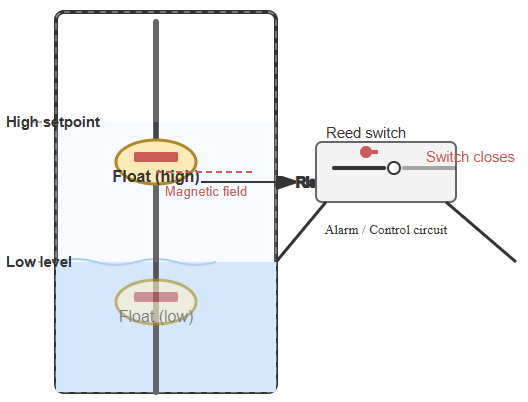
The following figure indicates a diagram illustrating a float switch showing a float moving with the liquid level in a tank.

The float mechanically activates a switch (e.g., a reed switch) at a specific high or low point. So, this figure helps visualize the mechanical operation of a float switch.

Float Switch Operation

Optical Level Sensors

Optical level sensors rely on light to sense liquid presence at a fixed point. They contain an infrared LED and a photodetector in the sensor tip. In air, the light reflects internally and reaches the receiver. 

When submerged, the light is refracted into the liquid, reducing the signal received. This change triggers a switch output. These sensors are compact and have no moving parts but may be affected by dirt or film on the lens.

Conductivity Level Sensors

Conductivity (or resistance) sensors use a probe with two or more electrodes. A low-voltage AC current flows between them. When a conductive liquid covers the electrodes, the circuit closes and current passes, indicating level detection. 

These sensors are simple and inexpensive but only work with conductive liquids, and electrode wear can occur over time.

Vibrating (Tuning Fork) Level Sensors

These sensors include a fork-shaped element that vibrates at a set frequency. When liquid or solid material touches the fork, its vibration frequency changes. The electronics detect this change and switch the output. 

Vibrating sensors are reliable, unaffected by temperature or conductivity, and require little maintenance. However, they must come into contact with the medium to function.

Continuous Level Measurement

Continuous level sensors provide ongoing measurement of the material height or volume. They produce a variable signal (such as 4–20 mA or digital) that represents the actual level. These sensors are more advanced and generally costlier than point-level types.

Ultrasonic Level Sensors

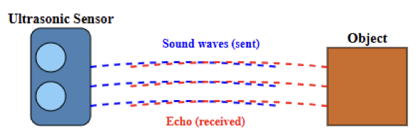
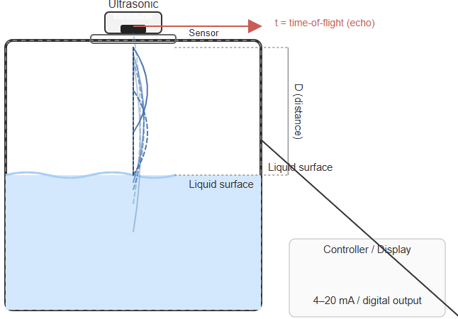
Ultrasonic sensors use sound waves to measure distance without contact. Mounted above the tank, they send high-frequency pulses toward the material surface. The sound reflects back to the sensor. 

The time taken for the echo to return (time-of-flight or ToF) is then used to calculate the distance. From this, the level is determined. They are well-suited for corrosive liquids but can be affected by foam, vapor, or turbulence.

Then the actual distance can be calculated using the following basic formula:

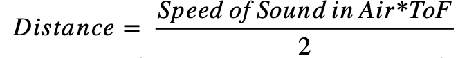
The division by 2 accounts for the round trip (going to the object and returning).


The following figure depicts a diagram showing an ultrasonic sensor mounted on top of a tank. It illustrates sound waves being emitted, reflecting off the liquid surface, and returning to the sensor.

Also, it specifies the distance D and the time-of-flight t labeled. This figure illustrates the time-of-flight principle used by ultrasonic sensors.

Radar Level Sensors

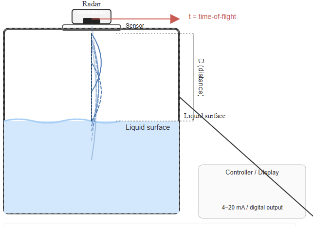
Radar sensors (microwave type) use electromagnetic waves instead of sound. The antenna transmits microwaves toward the material surface, and the reflected signal returns to the sensor. 

The time delay helps calculate the level. Radar sensors perform well in extreme conditions, high temperature, pressure, or dust and are unaffected by vapor. They are highly accurate and non-contact.

The upcoming figure represents a diagram showing a radar sensor emitting microwaves toward the liquid surface.

The reflections are used to compute the liquid level through time delay. The mentioned figure shows how radar waves measure level precisely.

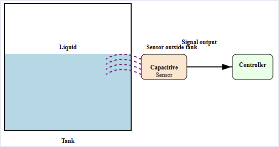
Capacitance Level Sensors (Continuous)

Capacitance sensors measure level using changes in capacitance. The probe acts as one plate of a capacitor, and the tank wall or a second probe acts as the other. As the material rises, the dielectric constant changes, altering capacitance. 

The sensor’s electronics convert this change into a level signal. These sensors are durable and have no moving parts.

Hydrostatic Pressure Sensors

These sensors measure the pressure exerted by the liquid column. The pressure at the bottom is proportional to the liquid height and density. Submersible sensors placed near the tank bottom detect this pressure. 

They then generate an electrical signal that corresponds to the liquid level. They are accurate but depend on constant liquid density for precise readings.

Guided Wave Radar (GWR)

GWR sensors combine radar and contact technology. A probe (rod or cable) extends into the tank, guiding microwave pulses downward. When the pulse hits the material, part of it reflects back. 

The time-of-flight determines the level. GWR sensors are very accurate and less affected by foam or turbulence than non-contact methods. This makes them reliable for challenging applications

Key takeaways: Types of Level Sensors

This article presented the different types of level sensors and their operating principles. Level sensors are fundamental components in both industrial and domestic systems. They ensure accurate monitoring, safety, and effective process control. 

These sensors are generally classified into point and continuous measurement types. Point sensors, such as float, optical, conductivity, and vibrating switches, provide simple on/off detection. 

They are ideal for use in alarm systems and level limit control. Continuous sensors, including ultrasonic, radar, guided wave radar, capacitance, and hydrostatic types, deliver real-time level data. They also provide precise measurements for accurate monitoring.

They are often used in automation and advanced monitoring applications. Selecting the appropriate sensor depends on factors such as the medium’s properties, tank design, temperature, and required accuracy. 

Each sensor type has its own advantages and limitations. Choosing the right one is essential for achieving optimal performance and long-term reliability.

FAQ: Types of Level Sensors

What are the main types of level sensors?

Level sensors are divided into point-level and continuous-level types.

When should I use a point or continuous sensor?

Use point sensors for full/empty detection and continuous sensors for real-time monitoring.

What are examples of point-level sensors?

Float switches, optical sensors, conductivity probes, and vibrating (tuning fork) sensors.

What are examples of continuous level sensors?

Ultrasonic, radar, guided wave radar, capacitance, and hydrostatic pressure sensors.

What factors affect sensor selection?

Material type, conductivity, tank design, pressure, temperature, and required accuracy.

Can level sensors work in harsh environments?

Yes. Radar and ultrasonic sensors handle heat, pressure, and corrosive media well.

What are some drawbacks of level sensors?

Float switches can jam, ultrasonics fail with foam, and radar sensors are costly.

Do level sensors need maintenance?

Yes. Regular inspection and calibration maintain accuracy and reliability.

What outputs do continuous sensors provide?

They give analog (4–20 mA) or digital outputs like Modbus or HART.

What’s the difference between contact and non-contact sensors?

Contact sensors touch the material; non-contact sensors measure from a distance.

Temperature Sensor Types

Temperature is a basic physical quantity measured and controlled in almost every field. From managing home climate systems to handling complex chemical reactions, temperature sensors play a key role in safety, efficiency, and quality. 

They work by converting heat energy into an electrical signal that can be interpreted. The range of available sensors can seem vast.

Nevertheless, knowing their main principles, pros, and limits helps in selecting the right one. 

This article explores the most common types of temperature sensors, detailing how they function and where they are best applied. It also details of how to choose them and what their trending future.

Contact vs. non-contact sensing

Temperature sensors fall into two main groups: contact and non-contact. Contact types, such as thermocouples, thermistors and RTDs need to touch the object or medium they measure. 

They sense their own temperature, assumed to match the target once thermal balance is reached.

On the other hand, non-contact sensors, like infrared thermometers, detect temperature remotely by reading the infrared energy emitted by an object.

Contact sensors

This section talks about the contact sensors.

Thermocouples

A thermocouple uses two different metal wires joined at one end. It works on the Seebeck effect.

The latter states that a voltage appears between two conductors when there is a temperature difference. 

The magnitude of the voltage depends on the temperature difference between the measuring and reference junctions.

Working principle of thermocouples

When the junction of both metals is heated or cooled, a small thermoelectric voltage is produced.

This signal, in millivolts, must be read and converted to temperature. For accuracy, the reference junction temperature must be known and compensated for.

Modern devices do this electronically.  The figure below illustrates a simple diagram of a thermocouple circuit showing the hot (measuring) junction and the cold (reference) junction connected to a voltmeter.

Types of thermocouples

Thermocouples are classified by material, which defines their range and traits. Common examples include:
Type K: Chromel-Alumel, general-purpose, wide range.
Type J: Iron-Constantan, common but narrower range.
Type T: Copper-Constantan, good for humid or cryogenic use.
Noble types (R, S, B): Made with platinum and rhodium for very high temperatures.

Thermistors

Thermistors are temperature-sensitive resistors made from semiconducting oxides. Unlike RTDs, they show a large, non-linear resistance change with temperature.

Working principle of thermistors

Two main kinds exist:
Negative Temperature Coefficient (NTC): Resistance drops as temperature rises. Used for sensing. See the next figure.
Positive Temperature Coefficient (PTC): Resistance increases with temperature. Used as resettable fuses or heaters.

Linearization

Because their response is highly non-linear, thermistors must be linearized to get precise temperatures. This is done using circuits or software, often through the Steinhart-Hart equation.

Advantages and disadvantages

Thermistors are very sensitive, quick to respond, and inexpensive. Their drawbacks are a limited range and fragility compared to thermocouples.

Resistance Temperature Detectors (RTDs)

RTDs measure temperature by tracking the resistance change of a metal. Platinum is the most common element due to its stable, repeatable behavior.

Nickel and copper are also used. As temperature rises, resistance increases in a nearly straight line.

Working principle of RTDs

An RTD passes a small constant current through the platinum element. The voltage drop is measured and converted to temperature using a calibration curve. A Pt100 RTD has 100 Ω at 0°C.

Construction

RTDs are built in several forms:
Wire-wound: Metal wire wrapped on a core and sealed. Precise but costly.
Thin-film: A thin platinum layer on a ceramic base. Smaller, faster, and cheaper.
Coiled element: A small coil placed in a ceramic form, allowing expansion and high accuracy.

The figure below indicates a diagram illustrating the construction of a thin-film RTD, showing the ceramic substrate and the thin platinum path (meander).

Wiring configurations

RTDs use wiring setups to correct for lead resistance:
2-wire: Simplest, least accurate.
3-wire: Most used, compensates for lead resistance.
4-wire: Most accurate, fully cancels lead effects.

RTD vs. thermocouple

Generally, RTDs are more accurate and stable than thermocouples. Nevertheless, they have a narrower temperature range and slower response time. In addition, they are more expensive due to the use of platinum.

Bimetallic strip thermometers

Bimetallic thermometers rely on thermal expansion. A strip of two metals with different expansion rates bends when heated.

Working principle

One end is fixed while the other moves. As temperature shifts, the bend moves a pointer on a dial.

This simple and strong design is used in thermostats and dial thermometers. The following figure depicts a diagram showing a bimetallic strip bending when heated. 

Notice that the metal with the higher expansion rate is on the outside of the curve.

Variations

To save space and increase sensitivity, the strip can be wound into a coil. This adds length and boosts movement and response.

Non-contact sensors

This section explains the non-contact sensors.

Infrared sensors

Infrared or pyrometric sensors measure temperature without touching the object. They sense the infrared radiation emitted by a surface.

Working principle of infrared sensors

Anything above absolute zero emits infrared energy. The sensor focuses this radiation onto a detector, often a thermopile. The detector converts it into an electric signal and shows the temperature.

Factors affecting accuracy

Accuracy depends on emissivity, a surface’s ability to emit radiation. Shiny materials have low emissivity and may cause errors. Some sensors allow emissivity adjustment to correct for this.

Advantages and disadvantages

Infrared sensors are great for moving, hot, or unsafe targets. They react fast and stay clean. Their limits include sensitivity to surface finish and ambient conditions.

Semiconductor-based sensors

Semiconductor temperature sensors are ICs that use the temperature-dependent traits of semiconductors. They are widely used in electronics for monitoring.

Working principle

Most use the voltage drop across a diode junction. By running two transistors at different current levels, the voltage difference shows absolute temperature. This is converted into a linear output.

Digital vs. analog output

They can output digital or analog signals. Digital types send direct readings via I²C or SPI. Analog versions give a voltage or current proportional to temperature.

Limitations

They are cheap and easy to integrate but have limited range and lower accuracy than thermocouples or RTDs. Response time can also be slower.

Choosing the right sensor for your application

Selecting a temperature sensor depends on several factors:
Temperature range: Match the sensor’s range to expected conditions. Thermocouples suit extreme ranges; RTDs and thermistors fit moderate ones.
Accuracy: RTDs and thermistors are more accurate within their ranges.
Response time: Thermistors and thermocouples respond faster. Infrared sensors give instant readings.
Durability: Thermocouples are rugged; thermistors are delicate.
Cost: Thermistors are cheapest, RTDs are priciest, and semiconductor sensors balance cost and performance.
Environment: Check for vibration, corrosion, and harsh conditions. Noble thermocouples resist heat and corrosion well.

The Future of Temperature Sensor

The future of temperature sensors is moving toward higher precision and smaller size. Wireless technology and non-contact methods are becoming more common.

New materials like graphene and other carbon-based nanomaterials will make sensors more flexible and sensitive. 

Advances in digital signal processing will boost accuracy and automation. The market will grow rapidly, driven by demand from healthcare, industrial automation, and the Internet of Things (IoT).

Key takeaways: Temperature Sensor Types

This article showed the study of the different types, working principles, and uses of temperature sensors, how to choose, and their future. 

It further proved that temperature sensors are vital for precise control and monitoring in many systems. 

The right choice depends on needs like range, accuracy, speed, toughness, and cost. Knowing how each sensor works, from thermocouples and thermistors to RTDs and infrared types helps ensure performance and reliability. 

Semiconductor sensors have added compact, low-cost options for electronics, widening the range of choices.

As technology evolves, temperature sensing remains key to progress and innovation. 

FAQ: Temperature Sensor Types

What are the main types of temperature sensors?

The main types include:

  • Thermocouple — two dissimilar metals producing a voltage. 
  • RTD (Resistance Temperature Detector) — metal resistance changes with temperature.
  • Thermistor — semiconductor/metal-oxide resistor with large change in resistance. 
  • Semiconductor temperature sensor — integrated circuits using diodes or transistors. 
  • Infrared (noncontact) sensor — measures infrared radiation emitted by an object. 

Why are there so many different types of temperature sensors?

Because different applications have different needs for: temperature range, accuracy, response time, environmental durability, contact vs non-contact measurement. 

When should I use a thermocouple?

Use a thermocouple when you need a wide temperature range (including high extremes), ruggedness or minimal cost. They are less accurate but very versatile. 

When is an RTD a better choice?

An RTD is better when you need higher accuracy, better stability and repeatability, and you operate in moderate temperature ranges. 

What are the advantages and limitations of a thermistor?

Advantages: very high sensitivity in a narrow range, cost-effective. Limitations: nonlinear behavior, limited high-temperature range, more complex conversion.

What is a semiconductor temperature sensor and where is it used?

It is often an IC that uses temperature-sensitive voltage/current behavior of semiconductors. Used for integrated electronics, moderate temperature ranges, lower cost. 

What is a non-contact (infrared) temperature sensor and when would I use it?

A non-contact sensor detects infrared radiation from an object’s surface, so it can measure without touching the object. Use it for moving, hazardous, or inaccessible targets. 

How do I choose the right temperature sensor for my application?

Consider: temperature range, accuracy required, response time, durability/environment, cost, and whether contact or non-contact measurement is needed.

What is the difference between contact and non-contact temperature sensors?

Contact sensors must physically touch the object (e.g., thermocouples, RTDs). Non-contact sensors measure from a distance via emitted radiation (e.g., infrared). 

What is a Proximity Sensor in Automation?

A proximity sensor is a device designed to detect the presence or absence of nearby objects without the need for direct physical contact.

In other words, it can “sense” objects within a certain distance, even if it does not touch them. 

This makes it a key element in modern industrial automation systems, where efficiency and durability are critical.

These sensors play a central role in detecting when an object is within their detection zone. 

Depending on the technology used, they may rely on electromagnetic fields, ultrasonic sound waves, or light beamsto identify an object. Since the process is contactless, there is less wear and tear on mechanical parts. 

This means longer machine life, less frequent downtime, and reliable object detection.

This article talks about proximity sensors. It details about how they work, applications, varieties, challenges and limitations, and finally, their future. 

Different type of proximity sensor

How Proximity Sensors Work

Proximity sensors function by monitoring changes in their environment. When a target object enters the sensing zone, the internal circuit of the sensor detects this change.

The sensor then generates an output signal, which can be digital (on/off) or analog (distance-related).

The exact working principle depends on the sensor type. For instance, an inductive sensor looks for changes in electromagnetic fields, while an ultrasonic sensor measures the time delay of sound waves returning.

In all cases, the sensor acts as a bridge between the physical world and automation systems, ensuring that machines know what is happening around them in real time.

Flow of proximity sensor operation

Types of Proximity Sensors

Inductive Proximity Sensors

Principle

They generate an electromagnetic field. When a metallic object enters this field, it changes the inductance. The sensor detects this disturbance and produces an output signal.

Target material

Only metals (iron, steel, aluminum, copper).

Applications

Widely used in manufacturing plants to detect metallic parts on conveyors, in robotics for arm positioning, and in welding stations where heat and sparks make other sensors unreliable.

Advantages

Very robust and dependable. They resist dirt, oil, and moisture. They keep working in harsh environments.

Limitations

Cannot detect non-metallic materials such as wood, plastic, or liquids. Their detection range is short (usually a few millimeters).

Capacitive Proximity Sensors

Principle

They create an electrostatic field. When an object enters, it alters the capacitance of the system. The sensor detects this variation.

Target material

Detects metallic and non-metallic substances. Suitable for plastics, powders, grains, liquids, and even glass.

Applications

Used in liquid-level monitoring (tank sensors), packaging machines, and quality checks where detection of non-metallic substances is crucial.

Advantages

Very versatile. Can detect objects even when hidden behind thin non-metallic walls (like a plastic tank).

Limitations

Sensitive to humidity, temperature, and dust. Range is also limited compared to ultrasonic or photoelectric sensors.

Capacitive sensor placed outside a tank, detecting the liquid level inside

Ultrasonic Proximity Sensors

Principle

Emit ultrasonic sound waves (above human hearing). Measure the time taken for sound to travel to the object and bounce back.

Target material

Can detect any material, regardless of shape, color, or transparency.

Applications

Used for liquid-level measurement, obstacle detection in robotics, parking sensors in vehicles, and material height detection.

Advantages

Longer detection ranges (up to several meters). Unaffected by dust, dirt, or surface color.

Limitations

Sensitive to temperature changes and air pressure variations. Have a blind zone directly in front of the sensor.

Ultrasonic sensor sending sound waves and receiving echoes from an object

Photoelectric Proximity Sensors

Principle

Rely on light beams (infrared or laser). Detection happens when the beam is interrupted or reflected by an object.

Target material

Wide range of materials including transparent items like glass or thin plastic.

Types

  • Through-beam: Transmitter and receiver are separate. The object blocks the beam.
  • Retro-reflective: Uses a reflector opposite the sensor. The object breaks the reflected beam.
  • Diffuse: The sensor detects the light reflected by the object itself.

Applications

Counting objects on conveyors, detecting misaligned labels, ensuring packaging quality.

Advantages

Long sensing ranges and fast detection speed.

Limitations

Can be disrupted by dust, dirt, or ambient light interference. Requires clear line of sight.

Magnetic Proximity Sensors

Principle

Use a magnetic field to detect magnets or magnetic objects.

Target material

Only magnetic materials or magnets.

Applications

Used in door security locks, cylinder position sensing in pneumatic/hydraulic systems, and safety interlocks.

Advantages

Can detect objects even through non-magnetic barriers like plastic, wood, or thin metal sheets.

Limitations

Useless for non-magnetic objects.

Applications in Automation

Proximity sensors are indispensable in industrial automation. They support productivity, safety, and precision. Common applications include:

Conveyor systems

Detect items moving on belts, helping control start/stop actions. This saves energy and prevents jams.

Robotics

Enable obstacle avoidance and navigation. Essential for autonomous robots in warehouses or assembly lines.

Assembly lines

Ensure correct placement of parts before welding, pressing, or fastening. Improve quality control.

Material handling

Used in sorting, packaging, and inventory management. Help ensure accurate product counts.

Safety systems

Act as protective barriers. If a person gets too close to dangerous equipment, sensors trigger emergency stops.

Process control

Monitor tank levels in food, chemical, and beverage industries. Maintain consistency and avoid spillage.

Benefits of Proximity Sensors

Using proximity sensors offers many benefits for industries:

Non-contact detection

No wear and tear on machines or the sensor itself. This extends life and reduces repair costs.

High reliability

Provide accurate and repeatable results even in demanding environments.

Durability

Built to handle dust, vibration, oil, and extreme temperatures.

Fast response

Can detect high-speed moving objects, critical in automotive and electronics manufacturing.

Versatility

Different types can detect metals, plastics, liquids, powders, and even transparent objects.

Challenges and Limitations

Despite their advantages, proximity sensors face some drawbacks:

Short range

Inductive and capacitive sensors have limited reach.

Environmental sensitivity

Dust, light, temperature, or humidity may cause errors in photoelectric or capacitive sensors.

Target restrictions

Some sensors work only with specific materials (e.g., inductive = metal only).

Interference

If multiple sensors are placed close together, signals can overlap, leading to false triggers. This requires careful design and spacing.

Table showing limitations of each sensor type

Future of Proximity Sensors

The future holds exciting developments:

IoT integration

Sensors will connect to IoT networks for real-time data sharing and remote monitoring.

Artificial Intelligence (AI)

Smart sensors will adapt to changes, predict failures, and improve efficiency.

Miniaturization

Smaller sensors will fit into compact devices, making them suitable for wearables and micro-machines.

Wireless sensors

These will reduce wiring costs and allow flexible installation.

Advanced sensing

Combining multiple sensor technologies (sensor fusion) will provide more accurate and intelligent decisions.

Expanding market

As industries move toward Industry 4.0 and smart factories, the demand for advanced sensors will grow rapidly.

Timeline diagram: Present-day → IoT → AI → miniaturization → wireless → Industry 4.0

Conclusion

Proximity sensors are fundamental to automation and smart industries. They detect objects without physical contact, which improves safety, reduces wear, and increases machine life. 

With different types available, they can adapt to a wide variety of applications, from robotics and conveyors to safety and process control.

Although they face challenges such as limited range and environmental interference, ongoing innovation in AI, IoT, and wireless technologies will overcome these barriers.

In the future, proximity sensors will be even more central to smart factories and intelligent systems, enabling machines to interact seamlessly with their environment.

FAQ: What is a Proximity Sensor in Automation?

What is the difference between inductive and capacitive sensors?

Inductive sensors detect only metals, while capacitive sensors can detect both metallic and non-metallic objects such as liquids and plastics.

Which proximity sensor works best in dirty or oily environments?

Inductive sensors are the most reliable in harsh and contaminated conditions.

Can proximity sensors detect transparent objects?

Yes, photoelectric sensors are designed to detect transparent items like glass or thin plastics.

What industries rely most on proximity sensors?

Automotive, robotics, packaging, food and beverage, and warehouse logistics.

Are proximity sensors expensive?

Prices vary depending on type and range, but they are generally affordable considering the efficiency and reliability they bring to automation systems.

What Is a Multimeter? A Complete Guide for Beginners

A multimeter is a versatile electrical tool used to measure key properties of electricity, such as voltage, current, and resistance.

It’s also referred to as a volt-ohm meter or multi-tester and is essential for diagnosing electrical problems in circuits, batteries, and appliances.

Whether you’re an electrician, a technician, or a DIY enthusiast, a multimeter is a must-have tool for ensuring electronic components are functioning properly.

Types of Multimeters

Multimeters come in two main types:

Analog Multimeters

Analog Multimeters use a needle to display readings. These are particularly useful for observing fluctuating signals.

Digital Multimeters

Digital Multimeters (DMMs) display numeric values on an LCD screen. They are more commonly used today due to their high precision, ease of use, and advanced features.

Key Functions of a Multimeter

A multimeter can measure:

AC Voltage (V~)

Alternating Current voltage is commonly used to test outlets and appliances.

DC Voltage (V–)

Most sensors and controllers use Direct Current (DC) voltage; also, you can find VDC in batteries and other direct current sources.

Current (A)

Measures the flow of electric charge, either in milliamps (mA) or amps (A).

Resistance (Ω)

Measures how much a component resists the flow of current.

Advanced digital models may also support additional functions like continuity testing, capacitance, temperature, frequency, and duty cycle measurements.

Multimeter Parts and Symbols

Understanding the parts of a multimeter helps you use it more effectively:

Display

Shows readings; either analog (needle) or digital (numbers).

Selector Knob

Used to choose what you’re measuring—voltage, current, resistance, etc.

Probes (Leads)

Two wires—black (common/ground) and red (positive)—used to test components.

Ports (Jacks):

  • COM (Common): Black probe goes here.
  • VΩmA: Red probe goes here for most measurements.
  • 10A or 300mA Jack: For high current measurements.

Common symbols include:

  • V~ or ACV: AC Voltage
  • V– or DCV: DC Voltage
  • A or mA: Current
  • Ω: Resistance
  • hFE: Transistor testing mode

Technical Characteristics of a Multimeter

When comparing multimeters, consider the following:

Resolution

This is the smallest change the multimeter can detect. Higher resolution is useful for precise readings.

Accuracy

An accuracy is the degree to which the measurement reflects the true value. Consumer-grade DMMs typically offer ±0.5% accuracy.

Input Impedance

Input impedance should be high to avoid altering the circuit under test. Most DMMs offer 1 MΩ to 10 MΩ.

Burden Voltage

The voltage drop caused by the multimeter when measuring current. Lower is better.

Practical Uses of a Multimeter

Multimeters are widely used for:

  • Testing batteries (e.g., checking if a battery is dead or charged).
  • Identifying live wires in AC outlets.
  • Diagnosing faulty components like resistors or capacitors.
  • Checking continuity in cables like coaxial or jumper wires.
  • Verifying power supply voltages in appliances or DIY electronics.
  • Detecting faulty chips or overheating on circuit boards.

How to Use a Multimeter

Here are the most common uses of a multimeter.

Testing Probes

Before using your multimeter, inspect it and the probes for physical damage. To test probe continuity:

  • Set to resistance (Ω).
  • Touch black and red tips together.
  • You should get a reading close to 0.5Ω. Replace probes if significantly higher.

How to measure AC Voltage with a multimeter

  • Turn the selector to AC voltage (V~).
  • Plug the black probe into COM and the red into VΩmA.
  • Insert probes into the wall outlet (black to neutral, red to hot).
  • Read the display, usually around 120V for standard US outlets.

How to measure DC Voltage with a multimeter

  • Set the knob to DC voltage (V–).
  • Insert probes into the corresponding jacks.
  • Touch the black probe to the negative terminal and the red to the positive.
  • Read voltage. For example, a 9V battery should show close to 9V.

Tip: If your digital multimeter reading is negative, switch the black and red probes for a positive reading. It should be the same number, but without a minus symbol.

Don’t mix up the positive and negative sides with an analog multimeter. It may damage the tool.

How to measure current with a multimeter

  • Set to the highest current range first.
  • Move the red probe to the 10A or 300mA jack, depending on the expected current.
  • Break the circuit and insert probes in series.
  • Read the current and adjust the range if needed.

How to measure resistance with a multimeter

  • Remove the component from the circuit.
  • Set to resistance (Ω).
  • Touch probes to either side of the component.
  • Adjust the range until a proper reading appears.

How to test transistor with a multimeter

  • Set the multimeter to hFE.
  • Insert transistor legs into the labeled hFE socket.
  • Compare the displayed gain to datasheet values.

Safety Tips When Using a Multimeter

  • Never touch metal parts of probes during live testing.
  • Set the correct range before measuring.
  • Start with the highest range, then step down.
  • Always disconnect power before testing resistance.
  • Store the multimeter and probes properly to prevent damage.
  • Remove batteries from the device if storing long-term.

How to chose the right multimeter

Now that you understand the basics, you can pick the right multimeter for your job. Both types measure DC voltage, AC voltage and resistance. However, they have different strengths and weaknesses.

Digital Multimeters

Digital multimeters are ideal for heavy day-to-day users. They’re also a smart investment for homeowners who want simple and clear readings. Basic models are less expensive than more complex ones.

Key features include:

  • Easy-to-read digital display
  • Auto-shutoff to save battery
  • Auto-ranging to simplify measurement
  • High reliability and precision

Analog Multimeters

Analog multimeters are more affordable. They’re a good fit for DIYers who only need one occasionally. Avoid dropping an analog multimeter, as the impact can damage it.

These multimeters are known for these characteristics:

  • Cost-effectiveness
  • Taking longer to dial in a measurement
  • Measuring amps well, especially milliamps.

FAQ: What Is a Multimeter?

What is a multimeter used for?

A multimeter is used to measure electrical values like voltage, current, and resistance. It helps diagnose problems in outlets, batteries, appliances, circuit boards, and electronic components.

Can I use a multimeter to test a battery?

Yes. Set your multimeter to DC voltage, connect the probes to the battery terminals, and compare the reading to the battery’s rated voltage. This tells you if the battery is charged, low, or dead.

What is the difference between analog and digital multimeters?

Analog multimeters use a needle to show readings and are better for monitoring rapidly changing signals.

Digital multimeters provide precise numeric readings on a screen and are more common due to their accuracy and ease of use.

How do I measure resistance with a multimeter?

Set the multimeter to the resistance (Ω) function, disconnect the component from power, and place the probes on each side of the resistor. The display will show the resistance value.

Can a multimeter test AC and DC voltage?

Yes, most multimeters can test both. Use the V~ setting for AC voltage and V– for DC voltage. Always start at a higher range and work your way down for safety.

What are the common symbols on a multimeter?

  • V~: AC voltage
  • V–: DC voltage
  • A or mA: Current (amps or milliamps)
  • Ω: Resistance
  • hFE: Transistor gain

Is it safe to use a multimeter on a live circuit?

Yes, if used properly. Always hold the probes by their insulated grips, never touch the metal tips, and use a multimeter rated for the voltage range you’re testing.

For high-voltage mains, use Category II or higher-rated meters and consider calling a professional.

Why is my multimeter reading “1” or “OL”?

This means the resistance is too high for the current range setting. Try adjusting the range down until the multimeter provides a readable value.

How do I test continuity with a multimeter?

Set your multimeter to the continuity or resistance setting (often with a sound wave symbol).

Touch the probes to both ends of the wire or component. A beep or near-zero reading indicates good continuity.

How do I choose the right multimeter?

For basic use, a digital multimeter with auto-ranging and clear display is recommended. For occasional or budget use, analog models may suffice. Consider features like accuracy, resolution, and safety ratings when choosing.

Key Takeaways: What is a multimeter?

A multimeter is a powerful tool that combines multiple functions into one handheld device.

Whether you’re checking an old wall socket, verifying a car battery, or troubleshooting an electronic board, a multimeter provides the data you need to diagnose and fix problems with confidence.

By understanding its components, measurement types, and safety precautions, you can use a multimeter effectively and safely across a wide range of electrical tasks.

How to Convert 360 Fahrenheit to Celsius

Converting Fahrenheit to Celsius is one of the most complicated measurement conversions out there.

Today I am going to share with you how to do that, and I am going to provide an example of how to convert 360 Fahrenheit to Celsius.

Why is converting temperature units more complicated?

All measurement units have the same starting point; for example, the distance units cm and meters all start at zero. When you advance, you just add the units you advanced.

The most commonly used temperature units, Celsius, Fahrenheit, and Rankine, do not start at the same point; for example, water freezes at 0°C or at 32°F, so you cannot just do the simple conversion; you will need to run through an equation to get an answer.

The Difference Between Degree Celsius (°C) and Degree Fahrenheit (°F)

A thermometer can help us determine how cold or hot a substance is. Temperature is in most of the world measured and reported in degrees Celsius (°C). In the U.S. it is common to report the temperature in degrees Fahrenheit (°F). In the Celsius and Fahrenheit scales the temperatures where ice melts (water freezes) and water boils are used as reference points.

  • In the Celsius scale, the freezing point of water is defined as 0 °C and the boiling point is defined as 100 °C
  • On the Fahrenheit scale, the water freezes at 32 °F and boils at 212 °F

The Difference Between Degree Celsius (°C) and Degree Fahrenheit (°F)

A thermometer can help us determine how cold or hot a substance is. Temperature is in most of the world measured and reported in degrees Celsius (°C). In the U.S. it is common to report the temperature in degrees Fahrenheit (°F). In the Celsius and Fahrenheit scales the temperatures where ice melts (water freezes) and water boils are used as reference points.

  • In the Celsius scale, the freezing point of water is defined as 0°C, and the boiling point is defined as 100°C.
  • On the Fahrenheit scale, water freezes at 32 °F and boils at 212°F.

How to convert Fahrenheit to Celsius

0 degrees Fahrenheit is equal to -17.77778 degrees Celsius:

0 °F = -17.77778 °C

The temperature T in degrees Celsius (°C) is equal to the temperature T in degrees Fahrenheit (°F) minus 32, times 5/9:

T(°C) = (T(°F) – 32) × 5/9

or

T(°C) = (T(°F) – 32) / (9/5)

or

T(°C) = (T(°F) – 32) / 1.8

360 Fahrenheit to Celsius conversion

How to convert 360 degrees Fahrenheit to Celsius.

The temperature T in degrees Celsius (°C) is equal to the temperature T in degrees Fahrenheit (°F) minus 32, times 5/9:

T(°C) = (T(°F) – 32) × 5/9 = (360°F – 32) × 5/9 = 182.2222°C

So 360 degrees Fahrenheit is equal to 182.2222 degrees Celsius:

360°F = 182.2222°C.

How do you convert C to F without a calculator?

Without a calculator, there are many means to convert Celsius to Fahrenheit. Multiply the Celsius temperature by 1.8 and add 32 to get the Fahrenheit conversion. With this method you get the exact temperature conversion degree.

If I wanted to convert 182.2°C to F, I would take 182.2 x 1.8+32=359.96°F.

What is the difference between 1 degree Celsius and 1 degree Fahrenheit?

On the Celsius scale, there are 100 degrees between the freezing point and the boiling point of water compared to 180 degrees on the Fahrenheit scale. This means that 1 °C = 1.8 °F.

Which is colder C or F?

They are equally cold. It is at -40 that the two scales give the same reading. “The Fahrenheit and Celsius scales converge at −40 degrees (i.e. −40 °F and −40 °C represent the same temperature).

What is the Fahrenheit to Celsius ratio?

To convert temperatures in degrees Celsius to Fahrenheit, multiply by 1.8 (or 9/5) and add 32.

Conclusion

That is it; this is how to convert 360 Fahrenheit to Celsius. I hope it was somehow useful to you. Thank you for reading.