What is a Contactor?

A contactor is an electrical device, a specific type of relay. It is used to switch an electrical circuit ON or OFF. It is very useful for high-power applications for its capacity of to control circuits of high voltage or current levels. 

One of the common application examples is in electrical motors. Here, they can perfectly control the starting and stopping. Contactors are essential components in many industrial control systems. 

This is because they are designed to handle heavy loads and provide safety features. The present article addresses what contactors are, how do they work, where are they used, their pros and cons, and to do the maintenance and troubleshooting. 

The Contractors

Different from general-purpose relays, contactors are built with features for safety and durability. These characteristics include suppression of arc systems and the ability to be mounted on standard rails (DIN rails). 

In order to select a contactor, it depends on the load consumption of current and voltage. 

Key Components of Contactors

A contactor has several key parts, which work together to operate the switch. The main components are the coil (electromagnet), the contacts, and the enclosure (frame): 

  • Coil: An electromagnet used to create a magnetic field when energized.
  • Contacts: These are the actual electrical switches that are physically moved by the coil due to its magnetic field.
  • Enclosure (frame): This provides a case for the internal components

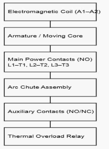
The following figure illustrates a schematic for the internal components of a contactor.

Internal Components of a Contactor.

Working Principle

The coil is the most important part of the operation. It is used to generate a magnetic field when energized. This magnetic field is what makes the contactor switch the circuit. 

There must be a control voltage to activate the coil. This control voltage is usually much lower than the main circuit voltage. For instance, a contactor might control a 240 V motor, while its coil might only have 24 volts to activate. 

So, just to emphasize, the coil is a very important part, and there must be a control voltage for it to operate.

When power is applied to the coil, it creates an electromagnetic force. This force pulls a movable armature toward a stationary core. 

It is important that the control voltage to be exactly the same as coil-specified rating. When an incorrect voltage is applied, this could lead to catastrophic outcomes to the coil. 

In addition, the mechanical movement is physically operates the contacts. While, the main role of the contacts is to handle applied power. These are the ones that deals with the actual switching mechanism. 

They can be found in two main sub-parts: fixed and movable. Once the coil is energized, the movable ones touch the fixed ones. This makes the power circuit complete. By de-energizing the coil, springs pull the movable contacts away. 

Then the power circuit can no longer stay complete. Special metal alloys are selected for the contacts. These metals designed to withstand arc damage and mechanical wear. This harsh and sturdy design is essential for long service life. The choice of material guarantees a dependable connection every time.

The enclosure (frame) works as the back-bone of structural housing. It keeps all components securely in place. It also shields the device from external conditions. The enclosure is typically built from insulating materials. 

This helps protect operators from electric shock. It also reduces the entry of dust or moisture. The frame is designed for easy installation. It is commonly mounted on a standard DIN rail in industrial panels. The enclosure frequently contains the arc chutes as well.

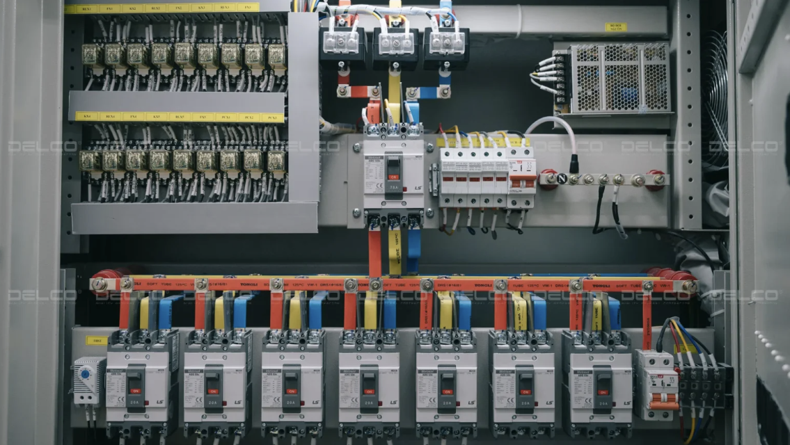
Consider an image below; it shows the assembled contactors with mounting points.

Arc suppression is an essential protective feature. High voltage and current create an electrical arc as the contacts open. This arc resembles a tiny lightning bolt. It can harm the contacts and pose a fire risk.

Contactors incorporate arc chutes to control this. Arc chutes are shaped chambers to cool and quench the arc rapidly. They guide the arc away from the contact surfaces. 

This approach greatly increases the lifespan of the contacts. Magnetic blowouts can also work together with the arc chutes.

Auxiliary Contacts

Contactors may include auxiliary contacts. These are additional sets of contacts. They operate independently from the main power contacts. Auxiliary contacts function in the control circuit. They often supply status signals to the control system.

For instance, they may activate a lamp to show that the main circuit is energized. They can be normally open (NO) or normally closed (NC). They move in sync with the main contacts. Their electrical ratings are much lower than those of the main contacts.

Overload protection

Overload protection is essential when using a contactor. A motor may pull excessive current if it is obstructed. This “overload” can harm the motor and wiring. Thermal overload relays are commonly paired with a contactor.

They track the motor’s current. If the current remains too high for too long, the relay trips. The relay interrupts the control circuit feeding the coil. This causes the contactor to drop out and stop the motor. The overload relay is a separate unit mounted alongside the contactor.

Similarities and Differences with Relays

A relay resembles a contactor but differs in capability. Relays are mainly for low-power duties. They support smaller voltages and currents. Contactors are engineered for heavy electrical loads.

Contactors typically include enhanced safety measures like arc suppression. Relays are used widely in electronic systems. Contactors dominate in industrial motor applications.

A relay may come with many contact arrangements. Contactors generally feature main contacts that are normally open.

Main Applications

This section covers the primary uses of contactors.

Motor starting

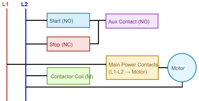
Motor starting is one of their main uses. Contactors are key components in motor starter circuits. A basic starter consists of a contactor, plus an overload relay. Pressing a “start” button energizes the coil.

Pressing a “stop” button deactivates the coil. Auxiliary-contact interlocks maintain safe starting and stopping sequences. This simple setup forms the foundation of many industrial control systems.

It allows centralized or remote operation of large motors. The upcoming figure indicates a very basic motor starter-schematic.

Lighting control

Lighting control is another major use. Large commercial or industrial lighting loads consume significant power. Contactors switch these large lighting circuits. A small wall switch can control the contactor coil.

The contactor then controls the main lighting supply for large groups of fixtures. This is more effective than using many small relays. It consolidates lighting control. This creates a strong and dependable solution for large facilities.

Capacitor switching

Capacitor switching requires specialized contactors. Power factor correction systems employ capacitor banks. Switching capacitors draws high inrush currents. Standard contactors would be damaged by these surges.

Dedicated capacitor contactors include pre-charge resistors. These resistors limit the initial surge current. The main contacts close once the surge is contained. This arrangement increases the service life of both the contactor and the capacitors.

Other Types of Contactors

Vacuum contactors

Vacuum contactors serve specialized environments. Their contacts sit inside a vacuum chamber. The vacuum eliminates arcing completely. With no air to ionize, arc formation is prevented. This makes them extremely durable.

They work well in very high-voltage applications. Mining operations and heavy industries frequently use them. Their sealed design is also safe where hazards exist. They require less upkeep compared to open-air designs.

Solid-State Contactors

Solid-state contactors are available but operate differently. They use semiconductor devices rather than mechanical contacts. With no moving parts, they avoid contact wear and arcing. They switch extremely quickly.

They are ideal for applications with repeated switching, such as heating control. However, they generate heat and need proper heat sinking. They may also cost more than magnetic contactors.

Maintenance and Troubleshooting

Maintenance is essential for contactors. Regular checks are advisable. Inspect for worn or pitted contacts. Watch for loose terminals. Listen for unusual sounds during use. A chattering noise may suggest low coil voltage.

Replace damaged contacts before they cause failure. Good maintenance ensures safety. It also extends the life of the system. Always follow the manufacturer’s instructions.

On the other hand, troubleshooting typical problems is straightforward. If a contactor vibrates loudly, the coil could be faulty. A mechanical obstruction may stop the armature from seating fully. If the device does not pull in, check the control voltage.

The coil may be burnt. If the load does not receive power, the main contacts may be defective. A multimeter is useful for testing. Always follow safety rules when inspecting equipment. Shut off all power before starting.

Key Takeaways: What is a Contactor?

This article explored what contactors are, how do they work and where are they used It also studied their pros and cons, and how to do the maintenance and troubleshooting.

So, awe have seen that contactor is a durable electrical switching device. It is built for high-power operation.

It uses a low-power input to manage large electrical loads. Its main components include the coil, contacts, and arc chutes. It is essential in industry.

It safely controls motors, lighting, and other large electrical systems. Knowing how it works helps in building safe designs. Choosing the correct contactor is important for dependable operation. 

FAQ: What is a Contactor?

What is a contactor?

A contactor is an electromechanical switch (like a heavy-duty relay). It is designed to open or close high-power electrical circuits such as for lighting, motors, heating or other heavy loads. 

How does a contactor work?

When a coil is energized, it creates a magnetic field. This pulls a movable core (armature) closing the main contacts and allowing power to flow.

On the contrary, when the coil is de-energized, a spring releases the armature. So, the contacts open to interrupt the load circuit. 

What makes a contactor different from a regular relay?

Contactors are for handling much higher currents and voltages than typical relays. They are designed for power-switching, while relays often deal with low-power control circuits. 

Where are contactors commonly used?

Motor starter circuit, large lighting banks and heating systems. Also, capacitor banks, and other high-power loads in industrial, commercial or heavy-duty environments. 

What are the basic parts of a contactor?

The main parts are: a coil (electromagnet), main power contacts (and sometimes auxiliary contacts), armature (movable core), an insulating housing (enclosure), and springs or return mechanism. 

Is a contactor safe for switching large loads remotely?

Yes, because the control circuit (coil) is electrically separate from the high-power circuit.  Furthermore, the user or control device can operate the contactor remotely and safely without handling high currents directly.

Do contactors make noise during operation?

Yes, many power contactors make a clicking or humming sound when the coil energizes and the contacts move.

The sound is normal and comes from the magnetic action. Excessive buzzing, though, may indicate loose laminations, coil issues, or the wrong voltage being applied to the coil.

What are the common causes of contactor failure?

Failures often come from overheating, dust build-up, or contacts wearing out due to arcing. Using a contactor beyond its rated load is another reason.

In some cases, poor ventilation or voltage fluctuations damage the coil. Preventive maintenance and choosing the right types of contactors helps avoid these problems.

What is a Remote Terminal Unit?

Remote terminal Unit (RTU), which also stands for Remote Telemetry Unit. It is used to control field devices (sensors, actuators).

This makes them one of the levels of the devices within a Supervisory Control and Data Acquisition (SCADA) system. 

RTUs control and monitor field devices through the collection of data from them. Then (as equivalent to PLCs) they convert this data into commands for the actuators, such as pumps and valves.

In this article we are going to explain what RTUs are, their functions, the pros and cons they possess, and how they relate to the future IIoT.

What is A Remote Terminal Unit (RTU)?

A Remote Terminal Unit (RTU) is a microprocessor-based device that is in charge of monitoring and controlling the field devices. 

Moreover, they act as an interface between the above-mentioned remote/field and the central station. 

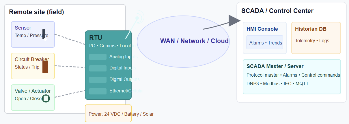
RTUs are more important when it comes to providing real-time data acquisition. And as we know, this is the backbone of an HMI and/or SCADA system. The figure below indicates the position of RTU within the SCADA system

Function of an RTU

  • Remote control: Since they are having digital outputs, these allow them to execute commands from the central SCADA system, like any actuators
  • Gathering of data: RTUs collect and interpret information coming from different field devices, meters, plus a number of other devices at remote sites. This could be analog and digital data, such as temperature, pressure, or the status of a switch. It depends of what we what to measure and control
  • Communication: No doubt RTUs have high capacity of communicating with the central SCADA system, often using various industrial communications protocols.
  • Data processing and logging: RTUs can perform some local processing, like calculating accumulated pulses from a meter, and can also log data for later analysis.
  • Alarm management: Should not be the less in SCADA system; RTUs also have the ability to detect and report sudden changes or events, such as a sensor exceeding a preset threshold, sending alarms to the central station

Relationship between an RTU and PLC

Fresh engineers, technicians or operation personnel, we mostly have a confusion of what RTUs are and what PLCs are. In this section we will briefly make it clear.

As stated above an RTU and a PLC are both used in industrial controllers, supporting rough environments.

But when it comes to RTUs, they are designed for more remote and long-distance monitoring and data acquisition.

On the other hand, PLCs are built for local real-time control of machines and processes, like directly getting the data from inputs and interpreting them to outputs (actuators). To say so, PLCs are generally used in factories and plants for precise and high-speed tasks. 

On the contrary, RTUs are used in distributed and harsh environments like oil fields or water utilities to transmit data back to a central system.  

Advantages

Rough environment

RTUs have a high capability to work in harsh conditions, such as high temperature and moisture.

Scalability

One of the characteristics of modern electronics devices/controllers is scalability. This means they must be easily expanded with additional modules and can be integrated into existing systems.

Data logging

This is another important point when it comes to the modern controllers. They must provide continuous data logging with important things like time and date, when alarm was triggered, etc.

Low power consumption

RTUs use automatic cycles as mentioned in the aforementioned point, which makes them well-suited for remote locations where power supply is limited. 

Disadvantages

Programming features

Most of the RTU controllers have limited programming features because they are pre-programmed.

Cyber-security

They may be vulnerable to the security due to their connection to HMI and/or SCADA system

Similarities

Although we have mentioned the confusion between the RTUs and PLCs, they both have some features in common. Here are a few that are mentioned

  • They both control field devices (sensors and actuators)
  • Their input and output modules are somehow similar
  • They are both very important to industrial automation 
  • And not to forget to mention, they are the backbone of SCADA system

Differences

Even if they have a lot of things in common, the big difference between RTUs and PLCs is the purpose of their design

  • While PLCs are designed for high-speed, real-time local control, RTUs are for harsh environments. 
  • PLCs are local controllers, while RTUs are for wide geographical areas

RTU in IIoT

In IIoT the central nodes are important in the ecosystem. So, these RTUs are becoming central nodes in IIoT ecosystems. They integrate with a growing number of devices. 

As we are in the age of AI, the recent RTUs are incorporating AI and machine learning for tasks like predictive maintenance and anomaly detection at the edge.

Conclusion

This article explored RTUs: what they are, where they are used, how they function and how they relate to PLCs. It also explained how RTUs are important in industrial automation. 

From this, we conclude that the RTUs are essential in our modern industrial automation. This also can mean that they are a very important component in the IIoT. 

Without underestimating the PLCs, RTUs are bridging the gap between physical field processes (sensors, actuators) and digital control systems to enhance operational efficiency. Also, the reliability and automation as above were confirmed.

FAQ: What is a Remote Terminal Unit?

What is an RTU?

A field device that collects data from sensors/actuators and sends it to a SCADA system for monitoring and control.

What does an RTU do?

It reads inputs, sends data to a control center, and executes remote commands.

Where is an RTU used?

In utilities and infrastructure: power substations, water systems, pipelines, and remote stations.

How does an RTU communicate?

Via serial, Ethernet, radio, cellular, or fiber links.

What signals can an RTU read?

Digital states (on/off), analog signals (4–20 mA, voltage), and status signals.

Can an RTU control equipment?

Yes. It can open/close valves, start/stop pumps, or operate breakers through its outputs.

How is an RTU different from a PLC?

RTUs focus on remote communication; PLCs focus on fast local control.

Why use an RTU instead of a PLC?

Because it supports long-distance communication, harsh environments, and low-bandwidth links.

Do RTUs support automation logic?

Many modern RTUs include basic logic but not as advanced as PLCs.

What protocols do RTUs use?

Common ones include Modbus, DNP3, and IEC 60870-5-101/104.

Do RTUs work without constant communication?

Yes. They store data and operate autonomously if the link drops.

What power supply do RTUs need?

Typically 24 VDC or battery/solar for remote sites.

Are RTUs rugged?

Yes. They are designed for outdoor, remote, and harsh environments.

Do RTUs support cybersecurity?

Modern RTUs include encryption, user authentication, and secure protocols.

Can RTUs integrate with IoT systems?

Yes. Many support MQTT, cloud gateways, and IIoT platforms.

What is a Pneumatic Actuator Valve?

A pneumatic actuator valve plays a vital role in numerous industrial operations. It relies on compressed air or gas to create either linear or rotary motion. This motion is then used to operate a valve mechanism.

The design is straightforward but delivers significant force. Industries across many sectors prefer this technology. You will find these actuators in oil and gas facilities, chemical plants, and general manufacturing. Their operation is dependable and secure.

This makes them suitable for locations where electrical equipment could create dangers. This article describes the basic operation, structure, and uses of these rugged devices. Gaining knowledge of pneumatic actuators is essential for achieving reliable automation and stable process control.

What is a Pneumatic Actuator Valve?

A pneumatic actuator valve transforms pressurized air into mechanical movement. The term “pneumatic” signifies the use of gases or compressed air. The word “actuator” refers to its role in providing movement or mechanical action. 

In essence, the device acts as a motor for the valve. It opens, closes, or regulates the flow of fluids or gases traveling through pipelines. The underlying idea is grounded in simple physics. Air pressure applied over a fixed area produces force. 

This force drives the actuator’s internal components. This principle offers a dependable and durable source of power.

Why Use Pneumatic Actuators?

Pneumatic actuators come with several key benefits. They are naturally safe for explosive or hazardous environments.

They do not rely on electrical power. This prevents the possibility of sparks that might ignite volatile substances. 

They are economical and easy to maintain. Compressed air is widely available and low cost. The internal parts are straightforward and sturdy. This contributes to long service life and limited downtime.

They also operate very quickly. This fast response makes them ideal for applications that need rapid flow control or emergency shut-off.

Core Components

A pneumatic actuator system consists of multiple essential parts. The actuator body is the primary unit. It contains a chamber or cylinder. Inside is a piston or diaphragm that responds to air pressure. The system also includes springs, seals, shafts, and linkages.

Everything connects to a compressed air source. A control device, such as a solenoid valve, directs the incoming airflow. All these components operate together. They convert a control signal into movement of the valve stem. A diagram would be useful for clarity.

The Actuator (Piston or Diaphragm)

Two major internal designs exist. Piston actuators use a solid piston that travels inside a cylinder. They withstand higher pressures and generate greater force. Diaphragm actuators employ a flexible membrane. Air pressure pushes against this diaphragm. 

These units are simpler and generally used for lower-pressure duties. They offer smooth and controlled motion. The decision between piston and diaphragm models depends on pressure demands and force requirements. Both achieve the same goal. They convert compressed air into straight-line movement.

Types of Motion

Pneumatic actuators are available in two main motion categories. Linear units travel in a straight path. They typically operate gate or globe valves. They raise or lower the valve stem. Rotary actuators create turning movement. 

They operate ball, butterfly, or plug valves. They rotate the stem by 90 degrees or more. The actuator type must match the valve design. This ensures proper flow control and reliable operation.

Air Supply and Control

These actuators depend entirely on a clean and stable air supply. The air source must be filtered and sometimes lubricated. This prevents damage to seals and internal components. Managing airflow is essential. 

Solenoid valves are commonly used for this purpose. They are electrically operated and open or close air passages based on control signals. These signals often originate from automated systems or control software. This arrangement allows accurate, remote valve operation.

Single-Acting Actuators

Single-acting actuators have a straightforward configuration. They use compressed air to move in one direction only. A built-in spring provides the return force. Air pressure compresses the spring during the working stroke. 

When air is released, the spring forces the piston or diaphragm back to its original position. This design is often described as “fail-safe.” If air supply is lost, the spring automatically moves the valve to a designated safe condition—either open or closed. This is essential for many safety-critical processes.

Double-Acting Actuators

Double-acting actuators use air pressure for movement in both directions. They eliminate the need for a return spring. Air enters one side of the piston to move it forward. Air enters the opposite side to move it back. 

This arrangement delivers maximum force in either direction. It is ideal where a fail-safe action is unnecessary. It provides full, balanced control for both opening and closing operations.

Control Systems and Instrumentation

Modern pneumatic actuators are usually part of advanced automated systems. Various instruments improve control accuracy. One key device is the positioner. It accepts a control signal, often 4–20 mA, and adjusts air pressure sent to the actuator. 

This allows the valve to stop at any position between fully open and fully shut. This is referred to as modulating service. Limit switches are also widely used. They send status signals to the control system. They confirm whether the valve is open or closed. This ensures the system always knows the valve’s condition.

Fail-Safe Mechanisms

Fail-safe capability is extremely important in many industries. As noted earlier, single-acting actuators provide built-in safety thanks to their return spring. Double-acting designs can also serve fail-safe roles with additional equipment. 

Air reservoirs can store emergency air pressure. This reserve activates the valve if the main air supply fails. Other external safety systems can close or open the valve in emergency conditions. Industry regulations often require some type of fail-safe feature. This prevents hazardous events during equipment failure.

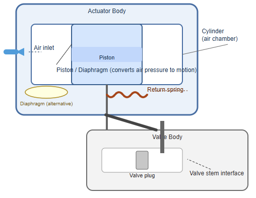
The following figure illustrates main components of the pneumatic actuator which are air inlet, cylinder, piston or diaphragm, spring, and the valve stem interface.

Actuator Sizing and Selection

Correct actuator sizing is vital. If an actuator is too small, it may not overcome process pressure to move the valve. Oversized units waste energy and may operate too aggressively. Sizing depends on several variables. 

These include the process pressure, valve type, flow requirements, and desired operating speed. Engineers use calculations and selection charts to determine the proper actuator. This choice is important. Proper sizing ensures reliable, efficient valve performance.

Materials of Construction

Pneumatic actuators are designed for durability. They are made from strong, long-lasting materials. Common choices include aluminum, stainless steel, and engineered plastics. Environmental conditions impact material selection. 

Harsh chemical environments often require stainless steel for corrosion resistance. Standard industrial settings may use lighter aluminum housings. Seals and O-rings usually consist of elastomers, such as nitrile rubber or Viton. 

These materials must match the air quality and ambient conditions. Proper material choice ensures long life and dependable service.

Maintenance and Troubleshooting

Pneumatic actuators generally need minimal maintenance. However, regular checks are essential. Inspections should look for air leaks, evaluate air quality, and verify tight connections. Air leaks reduce energy efficiency and slow actuator performance. 

Some models require periodic lubrication. Troubleshooting typically begins with the air supply. Technicians check air pressure and confirm control valves are functioning correctly. Most issues can be resolved with simple adjustments or routine maintenance.

Common Applications

Pneumatic actuator valves appear in nearly every industrial sector. They are critical in automated process systems. Water treatment facilities use them to regulate water and chemical flow. Food manufacturing relies on them for clean, precise material handling.

The oil and gas industry uses them for safety and process operations. They control the flow of hazardous fluids and gases. Even paper production plants depend on them. Their adaptability and reliability make them suitable for a wide range of tasks.

Comparison with Electric Actuators

Pneumatic actuators are often evaluated against electric actuators. Electric units operate using motors. They offer high-precision positioning and, in some cases, better energy efficiency. However, they are more complex and have higher costs. 

They may also be unsafe in explosive atmospheres. Pneumatic actuators are simpler, more economical, and safer in hazardous settings. The final decision depends on application needs, safety rules, and available budget.

The Future of Pneumatic Actuation

Industrial automation evolves continuously. Pneumatic technology is far from obsolete. New designs, improved materials, and advanced controls continue to develop. Smart pneumatic systems use sensors and digital networks such as IIoT. 

They provide real-time performance data. This enhances predictive maintenance and system efficiency. Future systems will likely blend pneumatic power with intelligent monitoring. The fundamental principle, using air to produce mechanical force, will remain essential.

Key takeaways: What is a Pneumatic Actuator Valve?

This article explored the purpose, operation, components, and applications of pneumatic actuator valves. Pneumatic actuator valves form a foundation of modern industrial automation. They are dependable, efficient, and safe. 

They use compressed air to regulate fluid movement with strength and precision. With different models single-acting, double-acting, linear, and rotary, they serve countless applications. 

Their rugged construction enables them to function in harsh environments. As automation technology advances, pneumatic actuation will continue to play a major role in reliable process control. Their widespread use ensures stable and secure industrial operations worldwide.

FAQ: What is a Pneumatic Actuator Valve?

What is a pneumatic actuator valve?

A device that uses compressed air to move a valve and control flow.

How does it work?

Air pressure pushes a piston or diaphragm, which moves the valve open or closed.

What types are available?

Linear actuators and rotary actuators; single-acting and double-acting designs.

Why use pneumatic actuators?

They are fast, reliable, safe in hazardous areas, and easy to maintain.

What are the main components?

Actuator body, piston/diaphragm, spring, seals, valve stem, and air ports.

What industries use them?

Oil & gas, chemical plants, water treatment, food processing, and manufacturing.

What is a single-acting actuator?

An actuator that uses air in one direction and a spring for the return stroke.

What is a double-acting actuator?

An actuator that uses air pressure for both forward and return movement.

What is a positioner?

A device that adjusts air supply to achieve accurate valve positioning.

What is fail-safe operation?

A feature that moves the valve to a safe position when air pressure is lost.

What are the advantages over electric actuators?

Better safety in explosive areas and simpler, lower-cost operation.

What are the limitations?

Requires clean air, offers lower precision without a positioner, and may be noisy.

How often do they need maintenance?

Regular leak checks, air filter cleaning, and seal inspection.

What valves can they operate?

Ball, butterfly, plug, globe, and gate valves.

What is a Water Control Valve?

A water control valve is an essential element in fluid-handling systems. Its main role is to manage water flow, pressure, or direction. It plays a vital part in municipal infrastructure, industrial operations, and household plumbing networks.

 Without these valves, water distribution would be chaotic and inefficient. They help maintain safety, improve water efficiency, and protect equipment from damage. This article defines what a water control valve is.

It also describes its components, reviews different valve types, and outlines key applications. Knowing how these devices work is crucial for proper water system management.

What is a Water Control Valve?

A water control valve is a mechanical device installed in a piping network. It modifies the route, quantity, or pressure of moving water. It can initiate or stop flow, adjust pressure levels, or redirect water.

Valves may be operated manually using handwheels or handles. They may also function automatically through electric, pneumatic, or hydraulic actuators. In automated systems, they act as final control elements.

These valves are built for durability. They must withstand the pressures and flow conditions of water systems.

Principles of Operation

The basic operating principle involves a movable component that changes the size of the water passageway. By adjusting this opening, the valve increases or decreases flow resistance. When fully open, the resistance is low. 

When closed, the resistance is nearly infinite. This prevents flow. The internal design determines how flow varies with valve position. This feature is important in process control. The valve may rely on water pressure or external power to move its internal components.

Key Components

Most water control valves share a set of essential parts. Each piece has a specific job. Together, they regulate the movement of water through the system.

The Valve Body

The valve body is the main structure of the valve. It forms the pressure boundary and holds all internal components in place. It also connects directly to the piping system. These connections can be threaded, flanged, or welded, depending on the installation.

Material choice varies with the application. Common options include cast iron, ductile iron, stainless steel, bronze, and PVC. Each material offers different levels of strength, corrosion resistance, and cost.

The Bonnet

The bonnet sits on top of the body and is usually bolted or screwed down. It acts like a cover that protects the internal components. Inside the bonnet is the packing box. The packing box seals tightly around the stem. This seal prevents water from leaking out where the stem moves in and out of the valve.

The Trim

The trim is the heart of the valve. It includes the stem, the disc or plug, and the seat.
The disc moves up or down to restrict or allow water flow. The seat provides a smooth, durable surface for sealing when the valve is closed.

The stem connects the disc to the operator or actuator. When the operator moves the stem, the disc follows. This movement directly controls the water flow.

The Actuator or Handwheel

This component provides the power to open or close the valve. A handwheel allows for manual control. It is simple and reliable. Actuators enable automatic operation. They may be electric, pneumatic, or hydraulic. 

They receive commands from a control system. Then they adjust the stem position to match the desired flow. Actuators are essential in systems that require precise control or remote operation.

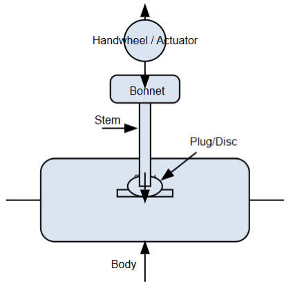
The following figure indicates diagram showing a cross-section of a typical globe valve, marking the body, bonnet, stem, plug/disc, seat, and handwheel/actuator.

Types of Water Control Valves

There are numerous water valve designs. Each one is intended for specific functions.

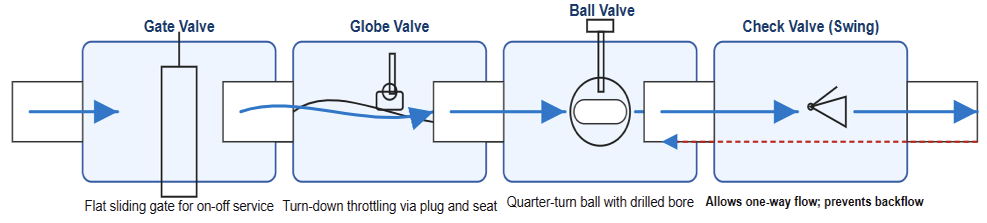
Gate Valves

Gate valves are intended for complete open or closed service. They use a flat gate that lowers to stop flow and raises to allow it. They create minimal flow resistance when open. They are not designed for regulating flow.

Globe Valves

Globe valves are ideal for throttling and precise control. Their internal path changes direction. This results in more pressure drop than gate valves. They are widely used when accurate regulation is required.

Ball Valves

Ball valves feature a rotating ball with a hole through its center. Turning the ball 90 degrees opens or closes the valve. They provide fast shutoff. They are well-suited for isolation duties. Their throttling capability is limited.

Butterfly Valves

Butterfly valves are common in large piping systems. They use a rotating disc attached to a stem. They require only a quarter turn to operate. They are lightweight and cost effective for larger sizes. They can be used for on/off or modulating service.

Check Valves

Check valves ensure one-way flow and prevent reverse flow. They operate automatically. They rely solely on water movement. Swing and lift check valves are the most common types.

Diaphragm Valves

Diaphragm valves regulate flow using a flexible diaphragm that presses against a weir. The valve body often features corrosion-resistant linings. They perform well in applications involving dirty water, suspended solids, or chemicals.

The next figure presents a diagram illustrating internal layouts and flow patterns of gate, globe, ball, and check valves.

Control Valve Characteristics

Flow characteristics describe how a valve responds as it opens or closes. They show how the flow rate changes with stem movement.

This helps designers choose the right valve for automatic control. It also helps operators predict how the system will behave.

Linear Characteristic

A linear characteristic produces a simple, predictable response. The flow increases at the same rate as the stem movement.

If the valve opens halfway, the flow is roughly half of its maximum. This makes control easier to tune. It is often used in systems that stay fairly stable.

Equal Percentage Characteristic

In an equal percentage valve, each small stem movement creates a percentage based change in flow. At low openings, the flow increases slowly.

As the valve opens more, the flow rises much faster. This allows the valve to handle large changes in pressure drop. It is common in heating, cooling, and industrial processes.

Quick-Opening Characteristic

A quick-opening valve delivers a large amount of flow with very little movement. Most of the capacity appears in the first part of the stroke.

This makes it ideal for on-off service. It is often used for safety functions, fast filling, or emergency shutoff.

Applications of Water Control Valves

Water control valves are used in a wide range of settings. They ensure proper flow management, system protection, and efficient water distribution.

Their versatility makes them essential in both simple and complex waterhandling environments. 

From large industrial plants to residential plumbing, these valves maintain safe operation and support consistent water quality.

Water Treatment Plants

Valves regulate water movement during filtration, chemical dosing, and settling processes. This ensures proper sequencing. Water treatment facilities rely on multiple valve types to manage the flow between processing stages. 

For instance, isolation valves allow maintenance crews to shut down individual sections without disrupting the entire plant. Control valves help maintain specific flow rates required for coagulation, sedimentation, and disinfection. 

Specialized valves may also handle sludge removal, filter backwashing, or chemical injection. By coordinating these functions, treatment plants maintain safe, clean, and reliable potable water supplies for communities.

Irrigation Systems

They control water delivery to agricultural fields or landscaping systems. Automated irrigation uses electric valves. These provide accurate timing. In agricultural irrigation, valves are essential for distributing water evenly across large areas. 

They help farmers manage water resources efficiently, reduce waste, and optimize crop growth. Drip and sprinkler systems depend on valves to maintain correct pressure and deliver the right amount of water at the right time. 

Modern smart irrigation controllers use sensors and weather data to adjust valve operation automatically.

This improves water conservation and ensures plants receive consistent and appropriate hydration throughout seasonal changes.

Building Plumbing

These valves are found in residential and commercial systems. They provide isolation, reduce pressure, and prevent backflow. The American Water Works Association (AWWA) offers guidelines and standards for such components.

In buildings, water control valves support everyday activities such as drinking, washing, heating, and sanitation. Isolation valves allow plumbers to work on fixtures or sections of piping without shutting off water to the entire building.

Pressure reducing valves protect internal plumbing from excessive supply pressure. This extends the life of appliances and piping. Backflow preventers ensure that contaminated water cannot re-enter the clean supply. 

Commercial facilities may also use balancing valves in HVAC water systems to ensure consistent flow through heating and cooling circuits. Together, these valves contribute to safe, efficient, and comfortable building environments.

Maintenance and Selection

Choosing the right valve is crucial. Materials must be compatible with the water’s chemistry. Pressure and temperature ratings must match the system requirements.

Conclusion

This article explored the role and importance of water control valves in modern water systems. These devices are essential for regulating flow, pressure, and direction. They ensure that water moves safely and efficiently through pipelines and equipment. 

The wide variety of valve types, such as gate, globe, ball, butterfly, diaphragm, and check valves allows engineers and operators to choose the best option for each application. They may be used for isolation, regulation, or backflow prevention. 

Selecting the correct materials, size, and flow characteristics is crucial for reliable performance. It is also important for long term durability. With proper maintenance, water control valves help prevent system failures.

They also reduce energy consumption and maintain consistent water quality. Though often unnoticed, they are critical components. They support the daily functioning of homes, industries, and municipal systems.

Frequently Asked Questions

What is a water control valve?

A water control valve is a device that regulates the flow, pressure, or direction of water in a system.

What does a water control valve do?

It opens, closes, or modulates flow so water can be controlled safely and efficiently.

Where are water control valves used?

They are used in plumbing, irrigation, water treatment plants, and industrial systems.

How does a water control valve work?

It uses a movable element, like a disc or plug, to change the opening inside the valve and adjust flow.

Can these valves operate automatically?

Yes. Actuators can move the valve using electric, pneumatic, or hydraulic power.

What materials are they made of?

Common materials include brass, stainless steel, ductile iron, bronze, and PVC.

What types of water control valves exist?

Common types include gate, globe, ball, butterfly, pressure-reducing, and solenoid valves.

Do water control valves help save water?

Yes. They control pressure and flow, which reduces waste and prevents leaks.

What problems can they prevent?

They reduce pressure surges, avoid pipe damage, prevent backflow, and maintain stable flow conditions.

How do I choose the right valve?

Match the valve to your system’s pressure, flow needs, water quality, and whether you need manual or automatic control.

What is a Transmitter and How it operate?

A transmitter is an essential component in industrial automation and communication systems.

In industrial settings, it measures a physical process variable. It then converts that reading into a standardized signal. 

This signal is then sent to a control system or a display device. Without transmitters, operators would be unable to observe key parameters. These parameters include temperature, pressure, or flow.

 In communications, transmitters send information over long distances. This article focuses on transmitters used in industry.

It explains what they are, their parts, categories, and their purpose. A solid understanding of transmitters is a core part of process control engineering.

What is a Transmitter and How it operate?

A transmitter senses a physical input and converts it into a standardized output signal. This input can be a process variable such as flow, pressure, temperature, or level. The output is usually an electrical signal like a  4-20 mA DC current loop.

It can also be a digital protocol such as HART, Foundation Fieldbus, or Profibus. The signal is proportional to the measured value. It can be reliably sent long distances.

This enables central control rooms to monitor processes in remote areas. It allows operators to observe them in real time.

Principles of Operation

Transmitter operation involves several conversion stages:

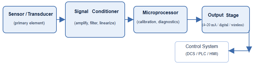
  1. Sensing: A primary sensor detects the physical variable.
  2. Conversion: A transducer converts the sensor’s small electrical change into a usable electrical signal.
  3. Transmission: The signal conditioning circuitry amplifies and formats the signal into the standard output. It is then sent wired or wireless to a receiving device.

The final output represents the measured variable in a simple, usable form. For example, 4 mA may represent 0%. 20 mA output may indicate 100% of the measurement range.

Key Components

Modern transmitters are advanced instruments. They are made up of several coordinated components.

The Sensor (Primary Element)

This component directly contacts the process. Examples include thermocouples for temperature and diaphragms for pressure.

They also include differential pressure devices for flow measurements. Its function is to sense the physical condition accurately.

The Transducer

The transducer changes the physical measurement into an electrical signal. For instance, a strain gauge on a pressure diaphragm transforms mechanical movement into small electrical resistance or voltage changes.

Signal Conditioning and Electronics

This section acts as the transmitter’s intelligence. Many modern units include a microprocessor. The electronics amplify, filter, and linearize the raw transducer signal. They apply calibration settings to maintain accuracy. 

They also convert the signal into the standard output form. These circuits are typically sealed. This protects them from tough industrial conditions.

The Enclosure

The enclosure protects the electronics from environmental hazards. Industrial sites often expose equipment to dust, humidity, and vibration.

Enclosures are usually built from stainless steel or cast aluminum. They are often designed to be explosion-proof in hazardous zones.

The Display/Interface

Many transmitters include a local display for real-time readings. They may also have buttons or magnetic tools for adjustment and calibration.

The following figure depicts a block diagram of an industrial transmitter showing the sensor/transducer, signal conditioner, microprocessor, and output stage.

Types of Transmitters by Measured Variable

Transmitters are classified based on the physical parameter they measure.

Pressure Transmitters