What Does VFD Mean?

A Variable Frequency Drive (VFD) is a device that controls the speed of an AC motor. It does this by adjusting the frequency and voltage supplied to the motor. Unlike basic motor controllers that only switch a motor on or off, a VFD allows precise speed control. 

This improves efficiency, enhances process control, and reduces mechanical wear. In simple terms, a VFD converts AC power into DC and then back to AC. However, it does so at a selectable frequency and voltage. 

This technology is widely used in modern industry because it helps save energy, prolongs equipment life, and allows processes to run more smoothly. This article explains what a VFD is, how it works, its benefits, common applications, and future trends.

Evolution of Motor Control

Before VFDs, motors could only operate in two states: ON or OFF. It was like driving a car that could only go full speed or stop. This caused a lot of energy waste in factories. Motors often did not need full speed, but they ran at maximum power anyway.

Early solutions tried to control speed using belts, gears, or mechanical clutches. These methods were inefficient and took up a lot of space. In the mid-20th century, engineers, including Vladimir G. Lukyanov, developed early variable-speed motor systems.

These systems allowed motors to run at different speeds depending on demand. Advances in power electronics, particularly the development of IGBTs (Insulated-Gate Bipolar Transistors), made VFDs more practical and reliable. 

The first commercial VFD appeared in 1967. Since then, VFDs have become essential in manufacturing, HVAC systems, water management, and many other industries. Over time, they became smaller, more efficient, and capable of controlling larger motors. 

Modern VFDs can communicate with other devices and even the internet, making them part of smart industrial systems.

VFD: Working Principle


A VFD controls motor speed through three main stages: the rectifier, the DC bus, and the inverter. These stages work together to convert and shape the electrical power so the motor runs exactly as required.

Rectifier Stage

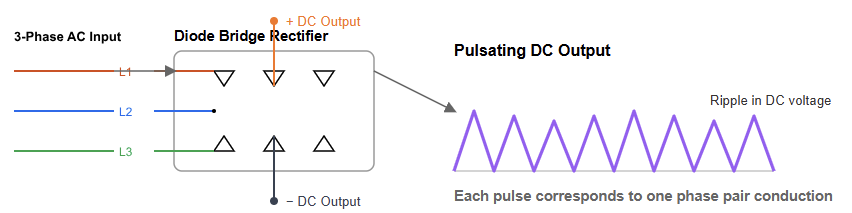
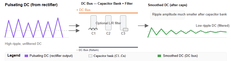
The rectifier is the first stage. It converts incoming AC power into DC using diodes. Diodes act like one-way gates, letting current flow in only one direction. The output is a pulsating DC waveform. 

This DC power is not yet smooth, but it is ready to be filtered in the next stage. The figure below shows the rectifier stage of a VFD.

What Does VFD Mean?

DC Bus Stage

The DC bus is the next stage. It smooths the pulsating DC using large capacitors. These capacitors act as filters, producing a stable DC voltage. This stable energy is then sent to the inverter. The DC bus also stores energy temporarily. 

This is useful when the motor needs to accelerate quickly or handle sudden load changes. The figure below illustrates the DC bus stage of a VFD.

Inverter Stage

The inverter converts the stable DC back to AC. However, the AC now has a variable frequency and voltage. It uses high-speed switches called IGBTs. These switches turn on and off rapidly in a pattern called Pulse Width Modulation (PWM). 


By adjusting the timing of these pulses, the VFD produces an AC output that precisely controls motor speed. This allows motors to run exactly as required for different processes. The figure below shows the inverter stage of a VFD.

Relationship between Frequency, Voltage, and Speed

The speed of an AC motor is directly proportional to the frequency of the power supplied to it. This is governed by the formula:

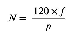
Where:

N = Speed in revolution per minute (RPM)

F = Frequency in Hertz (Hz)

P = Number of motor poles


By controlling fre frequency (f), the VFI can precisely control the motor’s speed (N). To maintain a stable magnetic field and prevent motor overheating, the VFI also proportionally adjusts the voltage supplied to the motor. This is known as the Volts-per-Hertz (V/Hz) ratio.

Benefits of Using a VFD

Energy Efficiency and Cost Savings

VFDs save energy by running motors only as fast as needed. For fans, pumps, and compressors, even a small speed reduction can significantly cut energy use. For example, lowering motor speed by 20% can save about 50% of energy. 

This reduces electricity bills and benefits the environment. Over time, these savings can pay for the VFD many times over.

Improved Process Control

A VFD lets you control motor acceleration, deceleration, and running speed. This is important in manufacturing, chemical processing, and conveyor systems. Smooth and precise motion ensures consistent product quality. It also prevents damage to equipment, such as belts, gears, and delicate materials being moved.

Extended Equipment Life

VFDs provide soft-start and soft-stop capabilities. This reduces mechanical stress on motors and connected equipment. Controlled acceleration and deceleration minimize wear on gears, couplings, and belts. 

As a result, equipment lasts longer, requires less maintenance, and reduces unscheduled downtime.

Built-in Protection

VFDs include protective features for overvoltage, undervoltage, and overheating. These safety functions prevent motor damage and costly breakdowns. Some VFDs can even monitor vibration or temperature, providing early warning before a failure occurs.

Common Applications of VFDs

HVAC Systems 

VFDs control fans, pumps, and compressors. They adjust airflow and water flow based on demand, reducing energy use.

Water and Wastewater Management 

VFDs control pumps in water treatment plants and municipal systems. They optimize flow and pressure, prevent water hammer, and save energy.

Industrial Fans and Pumps

 Large fans and pumps benefit from VFDs, operating efficiently under varying loads.

Conveyor Systems

VFDs allow smooth acceleration and deceleration. This protects products and machinery, improving efficiency and reducing maintenance.

Elevators and Escalators

 VFDs ensure smooth motion and safe speed control. They reduce energy use by adjusting motor speed according to load.

Mining and Heavy Industry

VFDs manage large motors in crushers, mills, and conveyors. Precise speed control increases productivity and reduces wear on heavy machinery.

Agriculture

 VFDs optimize irrigation pumps, grain handling, and ventilation systems. They save energy and extend equipment life.

Drawbacks and Considerations

Higher Initial Cost

VFDs are more expensive than simple starters. Energy savings often offset this over time.

Harmonic Distortion

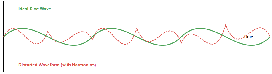
VFDs can create electrical noise called harmonics. This may affect other devices. Filters (passive or active) are used to reduce this problem. The figure below shows harmonic distortion.

Installation and Maintenance

Setting up a VFD requires skilled technicians. Proper configuration of programmable settings is necessary.

Motor Compatibility

Not all motors are suitable for VFDs. Older motors may not handle voltage stress well. It is best to use inverter-duty motors for reliable operation.

The Future of VFDs

VFDs are becoming smarter and more efficient. Many now connect to the Internet of Things (IoT) for remote monitoring, predictive maintenance, and data analysis. This allows factories to detect problems early, reduce downtime, and improve productivity.

New materials like Silicon Carbide (SiC) and Gallium Nitride (GaN) make drives faster, smaller, and more efficient.

In renewable energy, VFDs control motors in wind turbines and solar systems. They help balance power flow to the grid.


Advanced VFDs can even coordinate multiple motors for complex industrial systems, reducing energy use and increasing reliability.

Key Takeaways: What Does VFD Mean?

This article explained what a VFD is, how it works, its benefits, applications, and future trends. A VFD is more than just a motor controller. It is a smart device that saves energy, improves performance, and extends equipment life.

By precisely converting and controlling power, motors run exactly as needed. Although VFDs cost more initially, energy savings and reliability quickly offset the cost.

With IoT integration and advanced semiconductors, VFDs will remain essential in modern industry. They are key to creating cleaner, smarter, and more efficient systems worldwide.

FAQ: What Does VFD Mean?

What is a VFD?

A VFD is a motor controller that varies the frequency and voltage supplied to an AC motor so you can control its speed and torque.

How does a VFD work?

It converts incoming AC power to DC (via a rectifier), smooths the DC (via a DC-bus), then inverts it back to AC with a variable frequency and voltage to control the motor. 

Why use a VFD instead of just running a motor at full speed?

Because you can match the motor speed to what the process really needs. That leads to energy savings, lower mechanical wear, and better process control. 

Where are VFDs commonly used?

They’re used in pumps, fans, compressors, conveyors, HVAC systems, and any rotating equipment where the load varies. 

Can a VFD damage a motor?

If improperly sized, wired, or installed, yes, motors may be subject to higher voltage stress, harmonics, or cooling issues. But when properly used, a VFD actually extends motor life. 

What are the main benefits of using a VFD?

Key benefits: energy savings, speed control, smoother start-stop, less mechanical stress, and process optimization. 

What are some drawbacks or things to watch out for?

Higher initial cost, need for correct installation and settings, potential harmonic distortion in the supply line, motor compatibility issues. 

How do I choose the right VFD for my application?

You’ll look at the motor’s rated power, voltage, phase, speed range, load type (constant vs variable), control features, installation environment, and compatibility. 

How long do VFDs last?

With proper installation, cooling, and maintenance, VFDs often last 10-15 years or more. 

What’s the difference between a VFD, VSD and inverter drive?

These terms are often used interchangeably. A VFD (Variable Frequency Drive) is a type of variable speed drive (VSD). “Inverter drive” is another name focusing on the AC-to-AC conversion aspect.

How does Relay Work?

A relay is one of the most essential components in electrical systems. It acts as an electrically operated switch that allows one circuit to control another. A low-power signal can operate a high-power device safely through this mechanism.

Relays are important because they provide electrical isolation between control and load circuits. This ensures safe and reliable operation. They also make it possible to control large systems remotely or automatically.

This article introduces the main types of relays and explains how they work. It discusses types of relays: electromechanical, solid-state, and thermal relays in detail. It also compares them with contactors and shows where each device is best used. 

Electromechanical Relay: How It Works

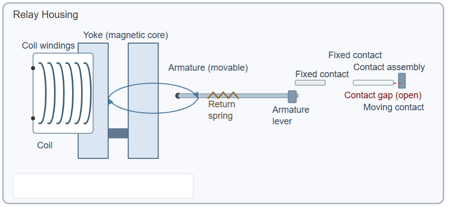
An electromechanical relay (EMR), works based on the principle of electromagnetism. Inside it, there is an iron core wrapped with a wire coil. This coil is part of the control circuit. When current flows through the coil, a magnetic field is produced.

The field attracts a movable metal lever called the armature. The armature connects to one or more electrical contacts. As it moves, the armature opens or closes the circuit that carries the load current. 

When the control current stops, the magnetic field disappears. A spring then pulls the armature back to its normal position.

This process makes or breaks the electrical connection physically. It allows a low-power signal to control a larger circuit safely. 

Key Components of an EMR

An electromechanical relay is made up of several important parts. The coil creates the magnetic field that drives the movement. The armature is the moving metal part that opens or closes the contacts.

The contacts are the points that actually complete or interrupt the load circuit. A spring provides the force to return the armature when the coil is de-energized. The yoke offers a low-resistance path for magnetic flux.

Finally, the housing protects all these components from dust, moisture, and vibration. These parts work together to perform reliable switching. A labeled diagram would make it easier to visualize each part 

The following figure illustrates a diagram showing the coil, armature, spring, yoke, contacts and housing.

Types of EMR: Normally Open vs. Normally Closed Contacts

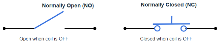
EMR can be designed in different configurations. The two main types are Normally Open (NO) and Normally Closed (NC). Normally Open contacts remain open when the relay coil is not energized. 

Once the coil is powered, the contacts close, allowing current to flow. Normally Closed contacts work in the opposite way. They stay closed when no current flows through the coil. When the coil is energized, the contacts open, cutting the circuit.

Some relays include both NO and NC contacts. These are called Double-Throw (DT) relays. DT relays allow switching between two different circuits using one common terminal. 


This makes them useful for applications that require alternate control paths. A figure showing how NO and NC contacts behave would be helpful. The above figure indicates a diagram of a NO vs NC contacts. 

Solid-State Relays 

Solid-State Relays (SSRs), are modern devices that perform the same function as EMRs. However, they have no moving parts. Instead, they use semiconductor components to switch the circuit. 

How do SSRs Work

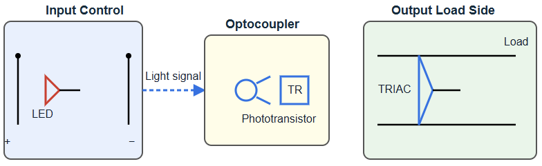
An SSR receives a low-power control signal at its input. This signal activates an optocoupler, which transfers the control signal using light. The optocoupler then triggers a semiconductor device, such as a thyristor, TRIAC or MOSFET.

Once activated, this semiconductor allows current to flow through the load circuit.  Because SSRs have no mechanical contacts, they operate silently. They also switch much faster than EMRs and last longer.

They are resistant to vibration and shock, which makes them ideal for demanding environments. However, SSRs have some limitations. They can produce heat during operation and often require cooling.

They are also more expensive than EMRs and usually have lower voltage and current ratings. Even with these drawbacks, SSRs are widely used in fast-switching and precise control systems. 

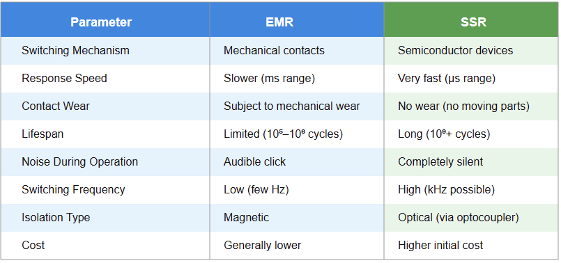
EMR vs. SSR: A Comparison

Choosing between an EMR and an SSR depends on the specific application. Each has clear advantages and disadvantages.

  • Electromechanical relays are strong and can handle high current levels. They also provide complete electrical isolation between circuits. However, their moving parts wear out over time. This makes them slower and less durable in repetitive switching situations.
  • Solid-state relays, by contrast, switch quickly and operate quietly. They have no moving contacts, so they last longer. They are excellent for precise and frequent operations.

Still, SSRs generate heat and usually cost more. Their voltage and current limits are also lower. Therefore, EMRs are best for general-purpose or heavy-duty applications, while SSRs are ideal for fast, low-noise systems. 

Thermal Relay: Working Principle

A thermal relay is used mainly to protect electric motors. It prevents damage caused by overheating or overload conditions.

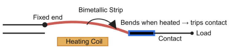
The heart of a thermal relay is a bimetallic strip. It consists of two different metals with unequal rates of thermal expansion. When too much current flows through the circuit, the relay’s heating coil warms this strip.

As the strip heats, it bends because one metal expands more than the other. This bending motion moves a set of contacts and opens the circuit. When the circuit opens, the motor power is cut off, preventing overheating.

After the fault is cleared, the relay can be reset manually or automatically. This simple design makes thermal relays reliable and widely used. 

Relay vs. Contactor

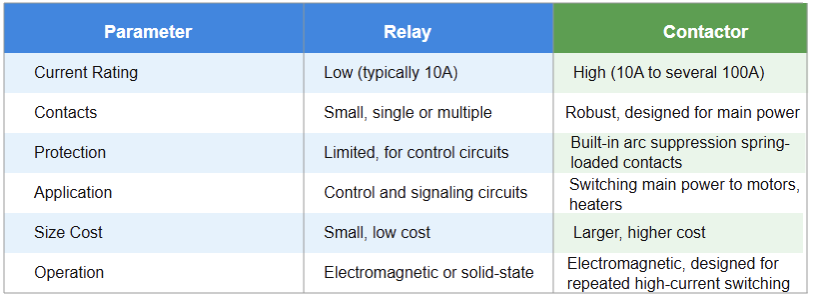
A contactor is similar to a relay but built for much higher power. It is commonly used to control heavy electrical loads, typically above 10 amperes.

Relays are usually smaller and meant for low-power or control circuits. Contactors, on the other hand, are used for motors, lighting systems, and industrial heating loads. They have stronger contacts and special features for protection.

These include arc suppression, spring-loaded mechanisms, and auxiliary contacts for added safety. Contactors are built to handle high currents and frequent switching. 

A relay often has both NO and NC contacts, while a contactor usually has only NO contacts for the main circuit. Contactors are larger and more durable, but also more expensive. 

Common Applications

Relays are used everywhere in electrical systems. In vehicles, they control headlights, horns, and starters. In household appliances, they manage motors, compressors, and heating elements.

Furthermore, in industrial automation, relays play a key role in control panels and process systems. They are used for logic control, signal transmission, and safety interlocks.

In addition, in power systems, relays perform protection and switching functions. They isolate faults and prevent equipment damage. In modern smart systems, relays are connected to IoT networks for remote monitoring and control.

Because relays separate low-voltage control from high-voltage operation, they improve both safety and flexibility.

Their ability to handle a wide range of applications makes them essential in almost every electrical environment.

Key Takeaways: How does Relay Work?

This article reviewed the operating principles of different relay types, their structures, and their uses. Understanding these concepts is vital for anyone working with control circuits or automation equipment.

So, the study helped us to understand that, the electromechanical relays use magnetic force to move contacts.

Solid-state relays use semiconductors to switch quietly and quickly. And, finally thermal relays protect motors from overheating and overloads.

Furthermore, we learnt that for high-power circuits, contactors are used instead of standard relays.

Each type has its advantages depending on the application. Knowing how they work helps engineers design safer and more reliable systems.

In short, relays are essential switching devices in electrical and automation systems. They remain one of the most important components in our modern electrified world.

FAQ: How does Relay Work?

What is a relay?

A relay is an electrically operated switch that uses a small control signal to turn a larger electrical circuit on or off.

How does a relay function?

When current flows through the relay’s coil, it creates a magnetic field. This field moves an armature that opens or closes the circuit contacts.

What are the main parts of a relay?

A relay typically includes a coil, an armature, contacts, a spring, and a protective enclosure.

What is the purpose of using a relay?

It allows a low-power control circuit to safely operate a high-power load while providing electrical isolation between the two.

What is the difference between Normally Open (NO) and Normally Closed (NC) contacts?

NO contacts remain open until the relay is energized, while NC contacts stay closed until it is energized.

What types of relays are there?

Common types include electromechanical relays (EMR), solid-state relays (SSR), and thermal overload relays.

What is an electromechanical relay?

It is a relay that uses a magnetic coil and moving contacts to switch electrical circuits mechanically.

What is a solid-state relay?

A solid-state relay uses semiconductor components instead of moving parts to perform fast and silent switching.

How does a thermal relay protect motors?

It uses a bimetallic strip that bends when heated by excess current, opening the circuit to prevent motor damage.

What is the difference between a relay and a contactor?

A relay is used for low-power control, while a contactor is designed for switching higher power loads like motors.

Can relays be used in DC and AC circuits?

Yes. Different relay types are designed to work with either AC or DC power depending on the coil design.

Why are relays important in automation systems?

They allow control systems to switch devices remotely, automate processes, and ensure electrical safety.

How long does a relay last?

Electromechanical relays typically last from thousands to millions of cycles. Solid-state relays can last much longer because they have no moving parts.

What causes a relay to fail?

Common causes include worn contacts, coil overheating, excessive current, or mechanical fatigue.

How can you test if a relay is working?

You can check continuity across the contacts using a multimeter. When the coil is energized, the contact state should change.

What are typical applications of relays?

They are used in cars, home appliances, power systems, control panels, and industrial automation equipment.

Do relays consume much power?

No. They typically use a small amount of power to energize the coil compared to the load they control.

Can relays be controlled by microcontrollers like Arduino?

Yes. Many relays are designed to work with low-voltage control signals from microcontrollers and PLCs.

Are relays safe to use?

Yes, when properly rated and wired. They isolate low-voltage control circuits from high-voltage loads for safety.

What are the signs of a faulty relay?

A relay may click but not switch, fail to energize, show burned contacts, or cause intermittent circuit operation.

How Does a SCADA System Work?

A SCADA (Supervisory Control and Data Acquisition) system is a critical industrial control system.

It monitors and controls industrial processes in real time. It combines hardware and software components that give operators centralized visibility and control over operations.

These systems are essential across industries such as energy, oil and gas, manufacturing, and water management. They optimize efficiency, ensure safety, and support data-driven decisions.

By collecting data from many field devices, SCADA systems process and display information. This allows operators to take necessary actions from a central location.

This article explains how a SCADA system works. It breaks down its components and shows the flow of data from the field to the control room.

Evolution and Modern SCADA

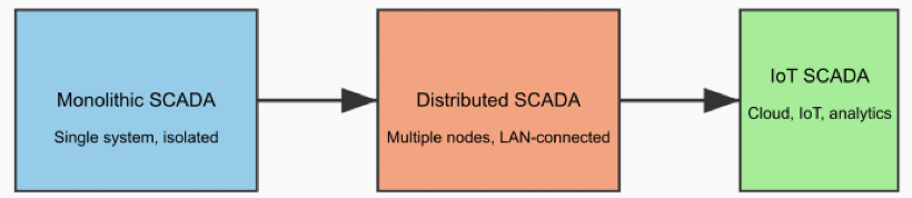
SCADA technology has evolved greatly over time. Early systems were monolithic and isolated. The second generation introduced distributed systems connected by local area networks (LANs). 

Third-generation systems adopted open protocols and networking technologies. Today’s SCADA integrates IoT devices, cloud computing, and advanced analytics. This provides scalability and remote access.

Operators can monitor and control processes from anywhere in the world. Cloud-based SCADA offers greater flexibility and massive data storage.

However, the shift to open and networked systems brings cybersecurity challenges. Modern SCADA solutions must prioritize strong security measures.

The Architecture of a SCADA System

A SCADA system is not a single product. It is a framework of interconnected components working together.

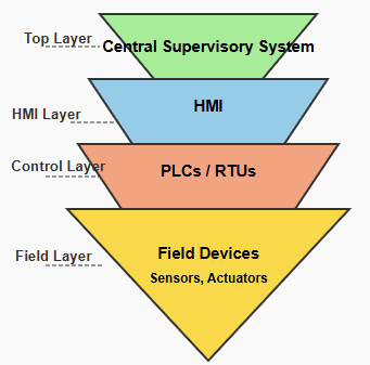
It usually has a multi-layered architecture, often described as a pyramid. The base layer includes sensors and other field devices.

The next layer contains local control units such as PLCs and RTUs. These controllers collect and process data from the field. The information is then sent to a supervisory computer at a central location. 

This central system uses software to process and display data on an HMI. Finally, communication networks connect all components together. This structure ensures reliable and efficient data flow and control.

Data Acquisition from Field Devices

The process begins with field devices. They are the eyes and ears of the SCADA system.
Field devices include sensors, gauges, meters, and actuators. They are spread across industrial plants or large areas.

Sensors measure physical parameters such as temperature, pressure, flow, voltage, or current. Actuators perform physical actions. They can open valves, start motors, or adjust machine settings.

This raw, real-time data is essential for monitoring the process. Without these devices, the SCADA system would be blind.

The Role of PLCs and RTUs

Programmable Logic Controllers (PLCs) and Remote Terminal Units (RTUs) form the brain of the local control layer.

Both are microcomputers designed for harsh industrial environments. PLCs are used for local, real-time control inside factories. 

RTUs handle control at remote sites or over large areas. Both collect data from field devices and convert analog signals into digital ones. They also execute control commands using predefined logic.

PLCs and RTUs act as bridges. They link the physical world of sensors with the digital world of central control.

Communication Networks

The communication network is the nervous system of the SCADA architecture.
It connects PLCs and RTUs to the central supervisory computers.

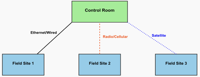
Communication may be wired or wireless. Wired connections often use Ethernet for speed and reliability.

Wireless links use radio, cellular, or satellite connections for remote areas. Communication protocols define how devices exchange data. Common ones include Modbus, DNP3, and IEC 60870-5. 

Modern SCADA systems use TCP/IP for network-based communication. The network must be both robust and secure. This ensures data integrity and timely delivery.

The Master Terminal Unit (MTU) or SCADA Server

The Master Terminal Unit (MTU) is the central command center. It consists of one or more computers running SCADA software. The MTU gathers data from all connected RTUs and PLCs. It acts as a server that processes and archives this data.

The stored information supports historical trending and reporting. The MTU also handles alarm management. It compares incoming data with predefined limits. If a parameter goes out of range, the system triggers an alarm.

The MTU can also send control commands back to the field. This happens automatically or when an operator issues instructions.

The Human-Machine Interface (HMI)

The Human-Machine Interface (HMI) is how operators interact with the SCADA system. It provides a visual display of the entire process. HMIs present information using graphics, charts, and mimic diagrams. 

An operator can quickly see the status of all equipment. For example, a pump icon might change color when it is running. Operators can issue commands using a mouse, keyboard, or touchscreen. 

This allows them to start a pump or adjust flow remotely. The HMI is essential for quick decision-making and troubleshooting.

Data Processing and Analysis

SCADA systems manage large amounts of data. The data from field devices is timestamped and stored. This historical data is extremely valuable for analysis.
It allows operators to spot trends and predict potential issues. 

They can perform predictive maintenance before failures occur. Reports generated from this data also support regulatory compliance. Modern SCADA systems use advanced analytics and artificial intelligence. 

These tools help optimize performance and forecast future problems. The data processing layer turns raw numbers into actionable insights.

Control Operations

SCADA systems provide both supervisory and automated control. Supervisory control involves human operators. They use the HMI to issue commands based on displayed data. Automated control is managed by PLCs or RTUs.

These devices react automatically to specific conditions. For example, if temperature rises above a limit, a PLC might start a cooling fan.

This dual system ensures flexibility and reliability. Automation handles routine tasks and emergencies. Human operators focus on major issues and strategic planning.

Alarm and Event Management

Alarm management is a core function of SCADA. Operators must be alerted when something abnormal occurs. The SCADA server constantly monitors all incoming data.
If a value exceeds a predefined limit, the system triggers an alarm. 

Alarms can be audible or visual. They may also have different priority levels. The system records all events, including operator actions. These logs are vital for troubleshooting and post-incident analysis. 

Modern systems can also send alerts via email or text messages. This ensures quick operator response.

Integration with Other Systems

Modern SCADA systems rarely operate alone. They often integrate with higher-level enterprise systems such as MES and ERP.

This integration connects operational technology (OT) with information technology (IT).

It allows data to move smoothly across all levels of the organization. For example, SCADA production data can feed into an ERP system for inventory tracking.

When linked with MES, it can improve scheduling and quality control. This connectivity increases efficiency and data visibility.

Key Takeways: How Does a SCADA System Work?

This article studied how the SCADA system works by It breaking down its components and detailed the flow of data from the field to the control room. So, in short SCADA system is a complex technology made up of many components. 

It enables remote supervision and control of industrial processes. The system gathers data from field devices such as sensors and actuators. PLCs and RTUs collect and process this data. 

It then travels over communication networks to the central supervisory system. Here, the SCADA software displays the data on an HMI. Operators can monitor the process, receive alarms, and issue control commands. 

Historical data is analyzed to generate reports and insights. With the rise of IoT and networked systems, SCADA continues to evolve. It remains vital for maintaining safety, efficiency, and real-time control in modern industries.

FAQ: How Does a SCADA System Work?

What is SCADA?

A system that monitors and controls industrial processes in real time.

What are the main components?

  • Field devices (sensors, actuators)
  • Controllers (PLCs, RTUs)
  • Communication networks
  • Central system with SCADA software and HMI

How does SCADA work?

Field devices collect data. Controllers process it and send it to the central system. Operators view and control processes via the HMI.

What are its key functions?

  • Real-time monitoring
  • Supervisory and automated control
  • Data logging and trend analysis
  • Remote access to processes

Which industries use SCADA?

Energy, oil & gas, water, manufacturing, and infrastructure.

How has SCADA evolved?

From isolated systems to networked, IoT-enabled, cloud-connected systems.

What are common risks?

Cybersecurity threats, integration challenges, and ensuring reliable data flow.

Can SCADA integrate with other systems?

Yes, with ERP and MES systems for better efficiency and data sharing.

How to Learn PLC Controller Programming

Programmable Logic Controller (PLC) programming is a vital skill in industrial automation. It controls machines and processes across sectors such as manufacturing, automotive, energy, and water treatment. 

Acting as the “brains” of automation, PLCs ensure efficiency, precision, and safety in modern systems. Learning PLC programming can seem challenging because it requires knowledge of hardware, software, and logic.

However, it becomes much easier when you follow a structured learning path. By combining theory with hands-on practice, beginners can confidently design, program, and troubleshoot control systems.

How to Learn PLC Controller Programming

This guide provides a step-by-step pathway from basic concepts to advanced automation techniques.

It helps aspiring engineers, electricians, and technicians build a strong foundation for real-world industrial applications.

Step 1: Understand the Basics

Start by learning what a PLC is. A Programmable Logic Controller is a durable industrial computer.

It is designed specifically to control machines and processes automatically. PLCs receive input signals from sensors, switches, and other devices. 

They send output signals to actuators such as motors, lamps, valves, and pumps. The PLC executes a program written to control these operations. This program responds to conditions detected by the input devices. 

Before PLCs, control systems relied on relay panels. These panels were large, hard to maintain, and inflexible.

PLCs replaced these mechanical systems with digital logic. Changes can now be made by editing the program instead of rewiring.

Understanding the basics will make learning programming easier. You will also understand industrial automation history and evolution.

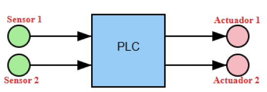
The figure below illustrates a simple diagram with a PLC positioned at the center. 

Arrows indicate the direction of signals flowing from the input devices, such as sensors, to the PLC. The from the PLC to the output devices, such as actuators.

Step 2: Learn About PLC Hardware

Next, study the key hardware components of a PLC system. The main parts are the CPU, power supply, and input/output modules.

The CPU is the brain of the system. It executes logic instructions and makes decisions based on inputs.

The power supply provides electricity to the CPU and other modules. I/O modules connect the PLC to field devices like sensors, switches, and actuators. PLCs are available in compact or modular designs.

Compact PLCs have fixed inputs and outputs and suit small applications. Modular PLCs allow additional modules to be added. They are suitable for large or expandable systems. 

Understanding how each component works helps in troubleshooting and system expansion.

Hands-on practice with a real or virtual PLC reinforces your understanding of the hardware layout.

Step 3: Choose a PLC Platform

Several manufacturers produce PLCs, including Siemens, Allen-Bradley, and Schneider Electric.

Each brand uses its own software environment and terminology. Allen-Bradley is common in North America, whereas Siemens is popular in Europe and Asia. 

Beginners should choose one platform and focus on it first. Mastering one platform helps you understand general PLC principles. Later, adapting to other platforms becomes much easier. 

Also, consider the availability of learning resources, tutorials, and simulation tools. Many manufacturers provide free materials, guides, and online training courses. Selecting the right platform with good resources accelerates your learning.

Step 4: Master Ladder Logic

Ladder Logic is the most common PLC programming language. It looks like an electrical circuit with two vertical rails and multiple horizontal rungs. It was designed for electricians and people familiar with relay diagrams. 

Learn basic instructions such as XIC, XIO, and OTE. These are the building blocks of all Ladder Logic programs. Start with simple examples, like turning on a lamp when a switch is pressed.

Then move to more advanced logic using timers, counters, and interlocks. Visualizing how current flows in a circuit helps you understand Ladder Logic easily. Practice creating small programs and simulate them to reinforce learning.

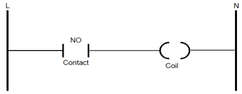
The upcoming figure details a diagram of a basic ladder logic rung. It shows a Normally Open (NO) contact connected to a coil. The rails are on the far left representing a power line (L), and right symbolizing a neutral (N).

Step 5: Get the Programming Software

Every PLC manufacturer provides proprietary programming software. Rockwell Automation uses RSLogix or Studio 5000. Siemens uses TIA Portal. Schneider Electric uses EcoStruxure Control Expert. 

These tools let you write, test, and upload programs to your PLC. Most software has free or student versions ideal for learning. Explore the interface and try creating small projects. 

Learn features such as tag management, cross-references, and diagnostics. These tools make programming and troubleshooting faster and more efficient.

Step 6: Use Simulation Software

You can practice PLC programming without owning physical hardware. Many software suites include simulation tools. Examples include PLCLogix 500 and OpenPLC Editor. Simulations allow you to test your logic safely. 

You can see inputs, outputs, and timers work in real time. This saves money and prevents mistakes on real equipment.

Over time, you can add virtual sensors and motors for realistic simulations. Simulation is a safe and effective way to gain experience.

Step 7: Practice with Small Projects

Hands-on practice is essential for learning PLCs. Start with small projects like controlling a motor or traffic light. You can also automate simple processes such as mixing or filling. 

Document every step with diagrams, flowcharts, and ladder logic drawings. Add features like alarms, timers, or safety interlocks as you progress. Small projects help build confidence and practical problem-solving skills.

Step 8: Move to Advanced Programming

After mastering Ladder Logic, explore other IEC 61131-3 languages. Function Block Diagram (FBD) uses graphical blocks for logic control. Structured Text (ST) is text based and resembles C or Pascal.

Learning multiple languages gives you flexibility for different projects. Modern PLCs allow hybrid programming, combining Ladder, FBD, and ST. This is useful when different parts of a system need different approaches.

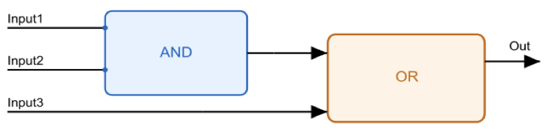
The subsequent figure exhibits a diagram showing a simple function block diagram.

It shows an AND block connected to an OR block. It also depicts that Inputs Input1 and Input2 feed the AND block, while Input3 feeds the OR block directly.

Step 9: Learn PLC Wiring

Programming alone is not enough. Physical connections are equally important. Learn how to wire digital and analog inputs and outputs correctly. Study diagrams showing connections to sensors, relays, and actuator