Networked digital infrastructures are increasingly used in industrial automation systems. The manufacturing processes of the future will be based on the merging of operational technology with the information networks of a company.
These fusions increase visibility, efficiency, and coordinated decision-making ability. But it also presents major cybersecurity threats to industrial settings. Worldwide, cyberattacks against critical infrastructure and manufacturing keep increasing.
Connectivity is used by attackers to get access to delicate control system components. Operating at the center of industrial processes are programmable logic controllers.
These controllers run drives, valves, motors, and other physical devices. Any compromise of their function could impede output and safety.
Thus, industrial cybersecurity seeks to safeguard these critical assets. It sets up regulated countermeasures against unlawful entry and hostile interference.
This article discusses fundamental ideas, PLC flaws, protective measures, and engineering obligations.
Connectivity is used by attackers to get access to delicate control system components. At the core of industrial processes are programmable logic controllers.
These controls control motors, valves, drives, and other physical devices. Any compromise of their function could disturb productivity and safety.
Industrial cybersecurity centers on safeguarding these indispensable assets. It sets up ordered barriers against illegal access and harmful intervention.
This post examines fundamental ideas, PLC flaws, protective measures, and engineering obligations.
Understanding Industrial Cybersecurity
Networked digital infrastructures are increasingly used in industrial automation systems. The manufacturing processes of the future will be based on the merging of operational technology with the information networks of a company.
This combination leads to higher transparency and efficiency. Also, it manages better coordination in decision-making.
Often, strategically targeting energy and infrastructure installations and nation-state actors may be among their aims.
In addition, espionage or geopolitical influence is also included. People within the organization can also create significant operational risks. Negligent configuration mistakes might open controllers up to exploitation.
Supply chain flaws open up more underappreciated attack paths. Malicious payloads might unwittingly come along in compromised software updates.
Flat network designs let attackers move quickly laterally. Adversaries could hunt for reachable PLC equipment once inside. These changing threats call for planned and aggressive cybersecurity defenses.
The lack of encryption or authentication mechanisms is a crucial factor in legacy protocols.
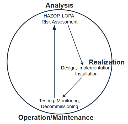
Consequently, industrial environments require specialized security approaches. Effective industrial cybersecurity integrates risk management with engineering practice.
It evaluates threats, vulnerabilities, and operational consequences systematically. Protective measures must preserve real-time performance characteristics.
Overly intrusive controls could impair deterministic execution cycles. Therefore, solutions balance security with operational reliability requirements.
Role of PLCs in Industrial Control Systems
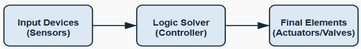
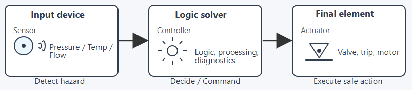
Programmable logic controllers execute control logic within repetitive scan cycles. They read inputs, process instructions, and update outputs predictably.
These cycles ensure deterministic machine and process behavior. PLCs supervise conveyors as well as the pumps. Turbines and robotic systems are also managed by them.
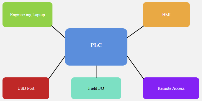
Modern PLCs support Ethernet connectivity and remote programming capabilities. Engineers can update firmware and adjust parameters through networks. While beneficial, this connectivity expands the potential attack surface.
Unauthorized users may attempt to upload altered logic. Malicious code insertion could manipulate physical equipment dangerously. Because PLCs directly control physical processes, consequences become immediate.
A compromised controller may stop production lines abruptly. It could also disable protective interlocks or safety routines. Therefore, PLC protection represents a central objective of industrial cybersecurity.
Expanding Cyber Threat Landscape
Industrial companies are increasingly being targeted by sophisticated and persistent cyber attacks.
Manufacturing companies all around are occasionally targeted in ransomware attacks. Attackers may encrypt engineering servers and demand financial payment. Phishing emails often compromise administrator credentials unintentionally.
Often strategically targeting energy and infrastructure installations, nation-state actors’ espionage or geopolitical influence may be among their aims.
Insider threats also present major operational risks. Negligent configuration mistakes might open controllers up to exploitation.
Supply chain flaws open up more underappreciated attack paths. Malicious payloads might unwittingly come along in compromised software updates.
Flat network designs let attackers move quickly laterally. Adversaries could hunt for reachable PLC equipment once inside. These changing threats call for planned and aggressive cybersecurity defenses.
Why PLCs Require Dedicated Protection
PLCs serve as gateways between digital commands and physical action. Manipulating controller logic directly influences mechanical behavior immediately. Even minor parameter modifications may alter product quality subtly.
Attackers recognize the strategic value of controller-level access. A successful PLC compromise demonstrates advanced technical capability publicly.
Financial extortion becomes effective when production halts completely. In critical infrastructure, disruption may affect public services directly.
Unlike office computers, PLCs operate continuously in harsh environments. Replacing damaged industrial equipment involves a high financial cost.
Recovery from cyber incidents may require lengthy system validation. Therefore, dedicated cybersecurity measures specifically protect PLC assets comprehensively.
Common Vulnerabilities in PLC Environments
Many industrial controllers were designed before cybersecurity became critical. Default credentials sometimes remain active after commissioning processes. Unencrypted communication protocols transmit commands in plain text.
Firmware updates may not be applied regularly or consistently. Engineering workstations sometimes connect without proper network segmentation. Removable media can introduce malware into control cabinets.
Physical access to panels may lack strict access control policies. Logging mechanisms sometimes provide insufficient forensic detail. When firewall settings aren’t properly configured, ports may stay accessible.
This can create unnecessary exposure to external networks. Together, these gaps significantly heighten the risk of security incidents. Addressing them strengthens the security posture significantly.

Core Defensive Strategies for PLC Protection
Defense in depth remains a fundamental cybersecurity architecture principle. Multiple layers of controls reduce single-point failure risks. Network segmentation separates operational technology from corporate networks.
Firewalls enforce strict traffic rules between defined security zones. Strong authentication mechanisms restrict unauthorized configuration changes. Role-based access control limits privileges to necessary functions.
Keeping systems regularly updated lowers exposure to existing software flaws.
This reduces the chances of those flaws being used against the system.
Continuous monitoring detects abnormal communication behavior rapidly. Incident response planning prepares teams for coordinated containment actions.
Security awareness training reduces the social engineering success probability. Asset inventory documentation improves visibility across industrial networks.
Risk assessments prioritize the protection of the most critical controllers. Together, these measures create structured and resilient defense frameworks.

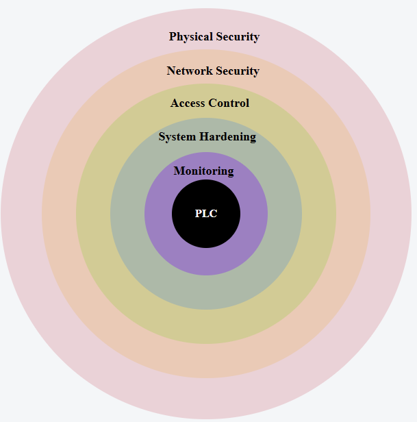
Defense in Depth Layers Protecting PLC Systems
Network Segmentation and Secure Architecture
Segmented network architecture limits the propagation of malicious traffic effectively. An industrial demilitarized zone isolates sensitive controllers securely. Traffic between enterprise and operational networks passes controlled gateways.
Access control lists define permitted communication paths precisely. Virtual LAN configurations further separate process areas logically. Remote access should occur through encrypted virtual private networks.
Continuous traffic monitoring identifies suspicious anomalies promptly. Proper documentation supports consistent architectural maintenance procedures. Periodic audits verify configuration integrity systematically.
Segmentation significantly reduces the potential impact of breaches. PLCs benefit from reduced exposure to external threats directly.

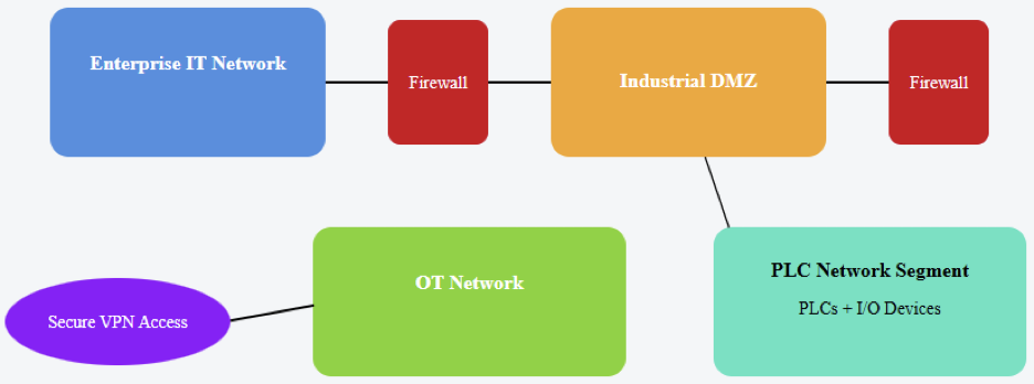
Layered Industrial Network Architecture with Segmentation and DMZ
Secure Configuration and Lifecycle Management
Secure PLC deployment begins during initial commissioning phases. Default passwords must be replaced with strong credentials immediately. Unused services and ports should remain disabled permanently.
Firmware must be updated following validated testing procedures. Backup configurations enable rapid restoration after security incidents. Change management processes control program modifications formally.
Time synchronization guarantees the correct correlation of the event logs. Physical locks safeguard control panels against unwanted tampering. Standardizing setups over comparable controller platforms is a security baseline.
Lifecycle management also includes recurring vulnerability evaluations. Retired equipment should be decommissioned securely.
These organized procedures build long-term resiliency. Effective lifecycle management shows responsible engineering stewardship.
Monitoring, Detection, and Incident Response
Continuous monitoring forms the basis of cybersecurity programs in the industrial sector. Intrusion detection systems analyze industrial protocol traffic patterns. Unusual command sequences may indicate malicious interference attempts.
These platforms collect events from various sources and analyze them together. Security teams investigate anomalies using structured forensic methodologies. Rapid isolation procedures limit operational disruption effectively.
Incident response plans define communication and recovery steps clearly. Regular exercises validate preparedness under simulated attack scenarios. Collaboration between IT and OT teams proves essential.
Post-incident analysis identifies improvement opportunities systematically. Lessons learned strengthen preventive and detective controls progressively.
Through disciplined monitoring, PLC environments maintain operational integrity reliably.
Standards and Regulatory Guidance
International standards offer planned advice on the execution of cybersecurity. The well-known IEC 62443 series is published by the International Electrotechnical Commission. This approach fully covers industrial automation system security.
Detailed cybersecurity risk management guidelines are provided by the National Institute of Standards and Technology. Its foundation enables methodical identification and alleviation techniques.
The International Society of Automation contributes to industry-specific security standards development initiatives. Compliance shows a clear commitment to safeguarding critical infrastructure assets.
Audits assess adherence to documented policies and controls objectively. Certification processes encourage continuous security improvement practices.
Standards also facilitate communication among technical stakeholders effectively. Alignment with recognized frameworks strengthens PLC cybersecurity governance.
Practical Engineering Perspective
From an engineering standpoint, cybersecurity integrates with system design. Security considerations should begin during project planning stages. Selecting controllers with robust security features proves advantageous.
Commissioning teams must validate secure configurations carefully. Documentation should include network diagrams and access policies clearly.
Balancing productivity and protection requires thoughtful decision-making. Excessively restrictive controls may hinder maintenance operations. Conversely, weak safeguards invite unacceptable operational risks.
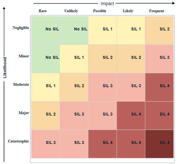
The tradeoffs must be evaluated by engineers through the use of structured risk analysis. Cybersecurity awareness is enhanced through continuous professional development.
Ultimately, disciplined engineering practice underpins effective industrial protection strategies.
Conclusion
This article introduced industrial cybersecurity as essential protection for automation systems. It explained how PLCs directly control critical physical processes.
The discussion examined vulnerabilities inherent within connected controller environments.
Defensive principles such as segmentation and hardening were described clearly. Monitoring, incident response, and lifecycle governance were emphasized strongly. International standards provided structured implementation guidance for organizations.
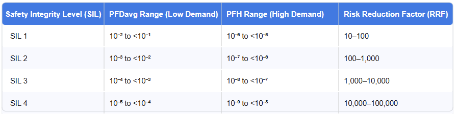
Practical engineering responsibilities were highlighted throughout the discussion. Implementing PLC protection measures strengthens cybersecurity posture under IEC 62443. It also sustains required safety integrity levels, such as SIL or performance level.
Organizations must treat industrial cybersecurity as a fundamental element of their strategy.
It should be embedded within the overall organizational framework. Proactive investment reduces disruption risks and financial losses. Secure control systems ultimately support resilient and sustainable industrial operations.
FAQs: What is industrial cybersecurity?
What is industrial cybersecurity?
It safeguards operating technology systems from illegal access and digital attacks.
What makes PLCs vital in cybersecurity debates?
PLCs regulate important industrial equipment and physical processes directly.
Attackers may compromise a PLC in what ways?
Through lax passwords, unpatched firmware, or unsafe network access.
If a PLC is hacked, what transpires?
Production may halt, equipment may break down, and safety hazards may arise.
Does network segmentation safeguard PLCs?
Yes, segmentation restricts threat spread and helps to limit illegal access.
Are legacy PLCs more susceptible?
Older versions sometimes miss modern authentication techniques and encryption.
Which norms direct industrial cybersecurity?
Structured advice is available from frameworks such as IEC 62443 and NIST.
Is PLC safety provided by antivirus software enough?
No, layered defenses and safe architecture are also needed.
For PLC cybersecurity, who is accountable?
Both operational engineering and IT bear some of the responsibility.
Industrial cybersecurity seeks mostly to do what?
To guarantee consistent, safe, dependable industrial activity.