In industrial automation, SCADA, HMI, and PLC are fundamental concepts that engineers, technicians, and operators encounter on a daily basis.
Even though these three terms are often mentioned together and sometimes mistakenly used interchangeably, they each serve a distinct and critical purpose.
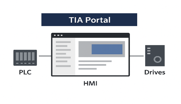
A PLC is the hardware that performs the direct control actions. An HMI, is the user interface that gives the operator the ability to interact with monitor, and control a process locally.
Finally, SCADA system is a larger, software-driven solution that oversees entire operations or even multiple geographically spread sites from one centralized location.
This article will explore the specific functions of each of these components, explain how they interact with each other, and clearly outline their main differences in order to remove common confusion.
Programmable Logic Controller (PLC)
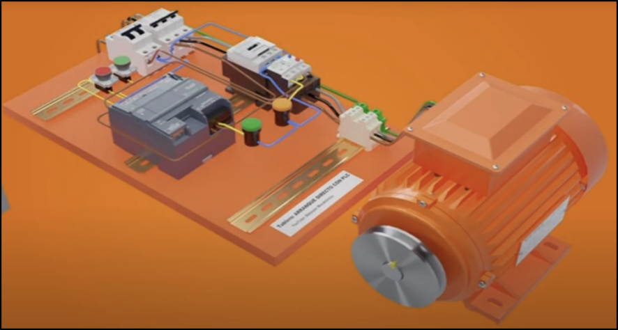
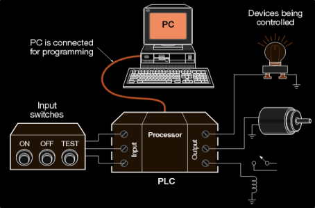
A PLC is essentially a rugged, industrial-grade computer that has been specially designed to survive and perform reliably in harsh factory environments. It is often referred to as the “brain” at the machine or process level.
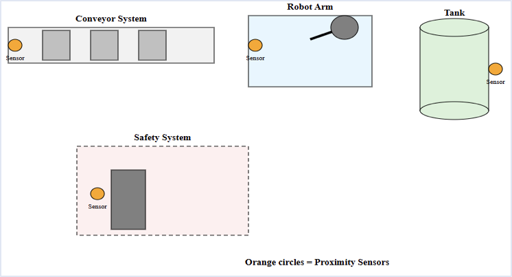
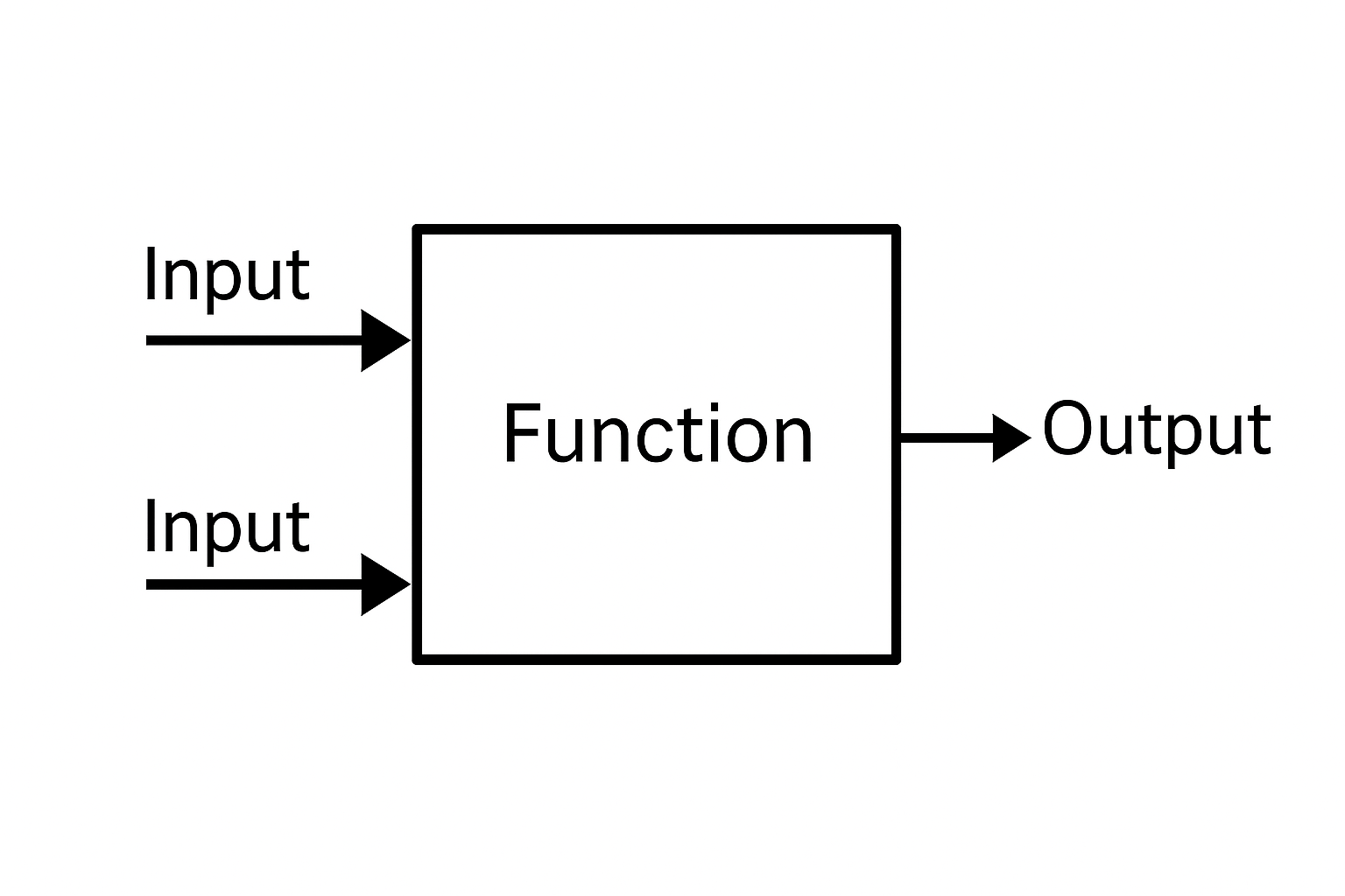
A PLC continuously receives information from various sensors and input devices. It executes a stored program that is based on logical decisions.
Finally, controls outputs that drive actuators, motors, lights, pumps, or other mechanical devices.
What is a PLC and how does it work?

Functionality of a PLC
Real-time control
The primary role of a PLC is to provide reliable, consistent, and high-speed control of a specific process.
It executes its program in what is known as a scan cycle – a rapid, repetitive loop where the PLC reads inputs, processes the program, and updates outputs almost instantaneously.
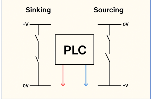
Input processing
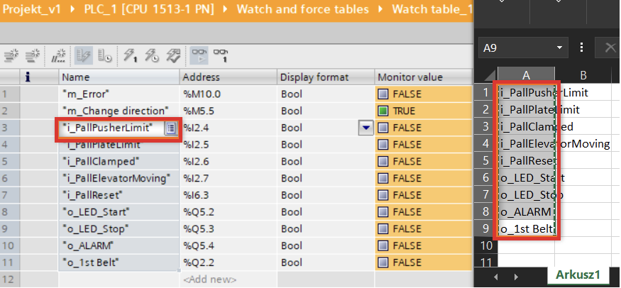
A PLC is able to handle both discrete and analog signals. Discrete signals are simple on/off inputs from devices such as push buttons or limit switches.
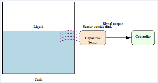
Analog signals, however, represent a range of values – for example, temperature readings, fluid levels, or pressure signals from sensors.
Output control
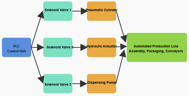
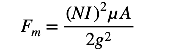
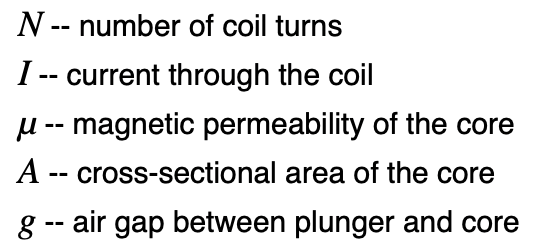
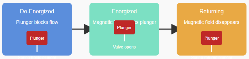
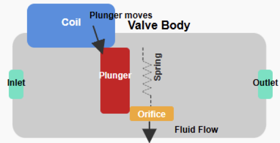
Once the logic is executed, the PLC sends precise commands to output devices. This may mean turning on a warning light, starting or stopping a motor, opening or closing a valve, or energizing a solenoid.
Programming flexibility
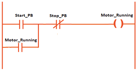
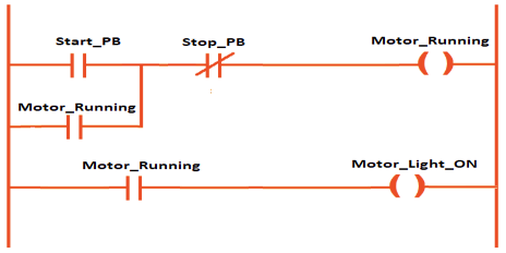
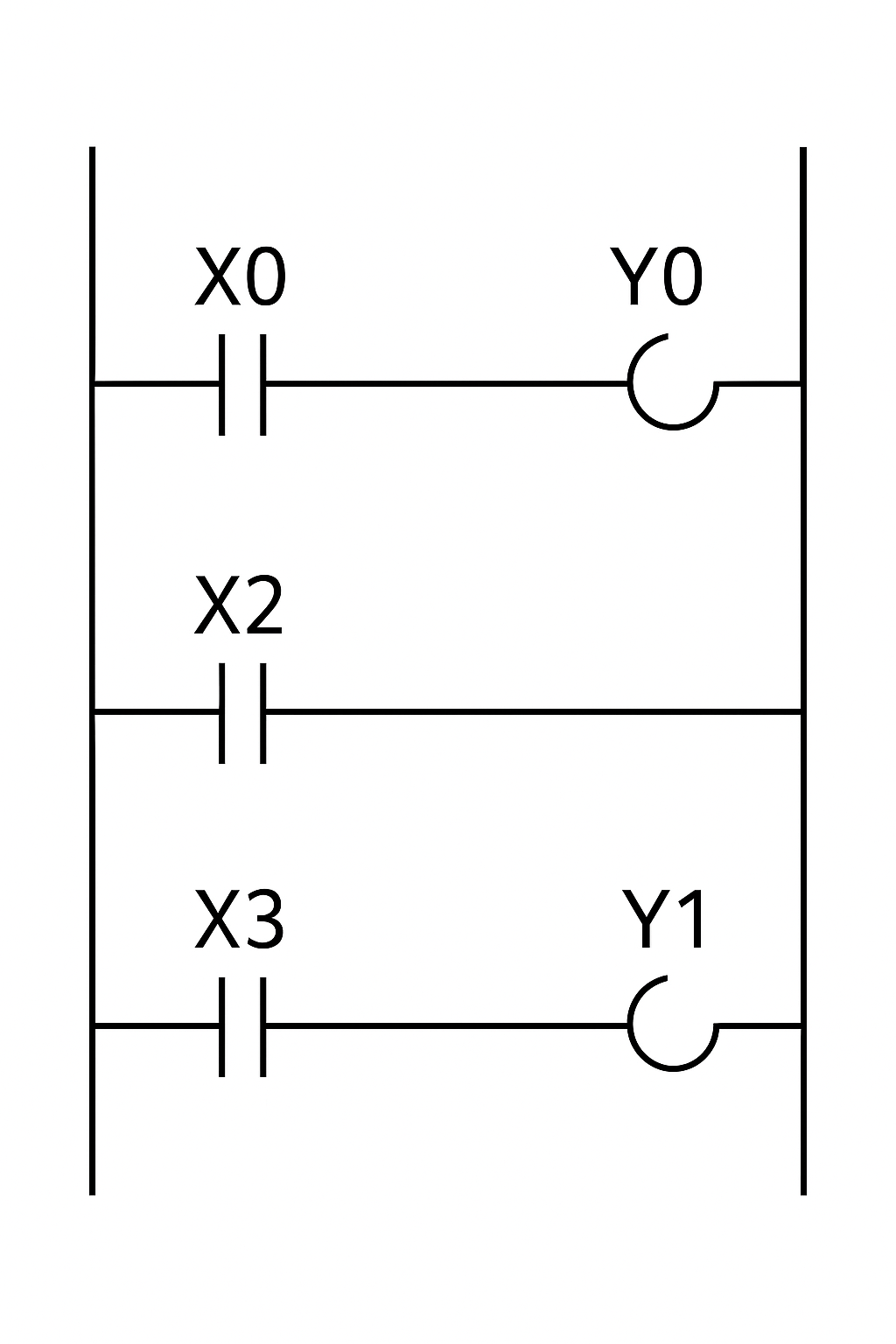
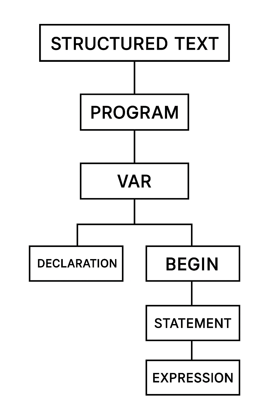
PLCs are programmed using specialized software provided by manufacturers. While ladder logic remains the most common programming language due to its simplicity and resemblance to electrical relay schematics, modern PLCs also support function block diagrams, structured text, and other languages.
Key Characteristics of a PLC
Hardware-based reliability
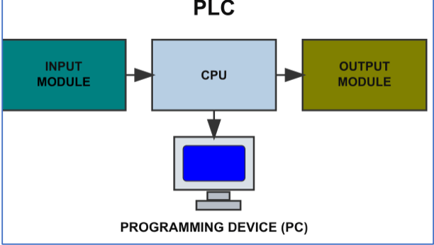
A PLC is a physical device made up of a central processing unit (CPU), memory for program storage, and input/output (I/O) modules that allow communication with field devices.
Localized scope of control
Typically, a single PLC is responsible for controlling one machine or a localized section of a process.
For example, one PLC may be dedicated to a packaging machine, while another manages a conveyor system.
Industrial-grade robustness
PLCs are designed to resist vibration, dust, heat, electrical noise, and other common hazards found in industrial settings.
This makes them far more durable than standard commercial computers.
Minimal data storage
Unlike large computer systems, PLCs are optimized for real-time control. They do not usually store large amounts of historical data because their main role is to execute tasks quickly and accurately.
Human-Machine Interface (HMI)
An HMI is the user-friendly face of an automation system. It is a visual interface that represents the status of a machine or process in a way that is clear and easy to understand for the operator.
In other words, it acts as the communication bridge between humans and industrial equipment.
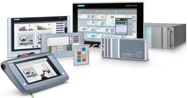
HMIs come in many different forms, such as touchscreens mounted on machines, physical control panels with buttons and indicators, or software running on a computer monitor.

Functionality of an HMI
Visualization
An HMI translates raw data from the PLC into a graphical, real-time display. Operators can see animations, charts, graphs, and diagrams that reflect the current condition of equipment.
For example, an HMI might show the exact level of liquid in a tank through a virtual gauge.
Control and operation
Beyond monitoring, an HMI gives operators the ability to control processes. Through on-screen buttons, sliders, and menus, they can start or stop machines, adjust speed, or modify setpoints and process parameters.
Alarms and diagnostics
A major function of HMIs is providing alerts whenever faults or abnormal conditions occur.
An operator might see a pop-up notification, hear an alarm sound, or view diagnostic data that helps identify the root cause of a malfunction.
Data presentation
While not as comprehensive as SCADA, an HMI focuses on displaying relevant data for a localized process or a specific machine.
This makes it easier for on-site personnel to react quickly and manage tasks without needing to rely on higher-level systems.
Key Characteristics of an HMI
Interface for interaction
The core purpose of an HMI is to provide a smooth, intuitive interface that enables humans to interact with machines.
Without an HMI, operators would have to rely only on physical switches and indicators.
Localized scope
An HMI is usually linked to one machine or process, giving operators a direct, local view.
Combination of software and hardware
An HMI setup consists of both the software that creates the graphical display and the physical hardware such as screens, panels, or keyboards that operators use.
Part of SCADA systems
While an HMI can function independently, it can also form part of a larger SCADA system where it acts as the local operator terminal.
Supervisory Control and Data Acquisition (SCADA)
SCADA systems represent the highest layer of industrial automation. Unlike PLCs, which control specific processes, or HMIs, which display localized information, SCADA provides a comprehensive and centralized overview of entire plants or even geographically distributed systems.
SCADA integrates both software and hardware to ensure supervisory monitoring and control across multiple processes.

Functionality of SCADA
Supervisory control
SCADA enables operators in a central control room to oversee entire production lines, utilities, or facilities.
They can send commands remotely to adjust operations without physically being near the machine.
Data acquisition
SCADA collects vast amounts of data from many different PLCs, RTUs (Remote Terminal Units), HMIs, and other field devices.
It continuously logs this data, which is later used for analysis and optimization.
Reporting and analysis
With its ability to generate detailed reports, trend charts, and historical logs, SCADA helps managers and engineers detect inefficiencies, predict maintenance needs, and identify long-term patterns in system behavior.
Alarm management
SCADA systems feature advanced alarm mechanisms that notify operators of critical events across the entire operation.
These alarms ensure that attention is quickly directed to the most urgent issues.
Key Characteristics of SCADA
System-wide scope
SCADA systems extend across multiple machines, entire production lines, or even sites that are miles apart, connected via communication networks.
Primarily software-based
Although SCADA interacts with hardware, its supervisory functions are mainly handled through powerful software platforms that aggregate and visualize massive amounts of data.
Centralized control
SCADA provides a command center for operators to manage and monitor everything in one place.
Historical data storage
Unlike PLCs, SCADA is designed for large-scale data storage. It can keep years of operational data, which is invaluable for performance tracking, compliance reporting, and predictive analysis.
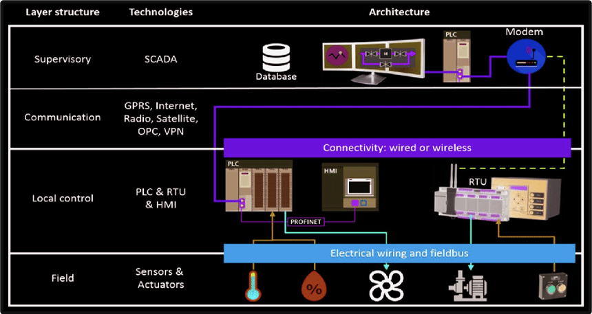
How They Work Together: A Layered Approach
In real-world industrial automation, SCADA, HMI, and PLCs do not work in isolation.
Instead, they operate in a hierarchical and layered structure that ensures efficiency, reliability, and clarity in operations.
The PLC (Control Layer)
At the lowest level, PLCs are directly connected to the physical equipment. They react in real-time to input signals and execute their pre-programmed logic.
For instance, if a sensor on a conveyor belt detects a passing product, the PLC may trigger a robotic arm to pick it up.
The HMI (Interface Layer)
Sitting above the PLC, the HMI gives operators an easy way to understand and interact with what the PLC is doing.
For example, an HMI screen might show the conveyor speed or the robotic arm status, and it allows the operator to make quick local changes by pressing on-screen buttons.
The SCADA (Supervisory Layer)
At the highest level, SCADA communicates with all PLCs and HMIs spread across the plant or different sites.
It gathers the data into a central database, allowing operators in a control room to monitor everything.
If an alarm is triggered by one of the PLCs, the SCADA system logs it, displays it, and ensures the operator can take timely action.
Comparison of SCADA, HMI, and PLC
| Feature | PLC | HMI | SCADA |
| Primary Function | Executes pre-programmed logic for a specific, localized task. | Provides a visual interface for human-machine interaction. | Manages and monitors an entire industrial process or multiple sites. |
| Scope of Control | Controls a single machine or process. | Displays and controls a machine or process locally. | Oversees the entire operation from a central point. |
| Nature of Device | Hardware-based industrial computer. | User interface hardware or software. | Software system that interacts with hardware. |
| Data Handling | Processes real-time signals; minimal storage. | Presents real-time localized data. | Collects, stores, and analyzes massive data sets. |
| User Interaction | Not intended for direct human use. | Direct operator interface. | Provides dashboards for supervisory control. |
| Key Output | Executes physical control actions. | Provides real-time feedback and manual inputs. | Generates reports, alarms, and a central overview. |
| Dependency | Can run independently but often sends data to SCADA. | Requires PLC/SCADA to function. | Relies on PLCs and field devices for input. |
| Core Purpose | Fast, repeatable execution of logic. | Easy local operation and monitoring. | High-level monitoring, optimization, and decision support. |
Key Takeaways: Differences between SCADA, HMI, and PLC
In summary, SCADA, HMI, and PLC are three vital components of industrial automation, but they each operate at different levels of the control hierarchy.
The PLC is the workhorse at the ground level, carrying out the detailed, real-time control logic for specific machines and processes.
The HMI provides the operator with immediate visual feedback and local control, making the operator’s job more intuitive and efficient.
Finally, SCADA sits at the supervisory layer, collecting, aggregating, and analyzing datafrom all the underlying PLCs and HMIs to give a complete, high-level view of operations.
By understanding their unique roles, it becomes clear that these technologies are not interchangeable.
Instead, they are complementary building blocks of a powerful, integrated industrial control system that enables factories, utilities, and plants to operate safely, efficiently, and intelligently.
FAQ: Differences between SCADA, HMI, and PLC
What exactly is a PLC, and what does it do?
A PLC is an industrial computer designed to control machinery and processes in real time.
It monitors inputs (sensors, switches, etc.), executes logic according to a program, and issues outputs to actuators (motors, valves, etc.).
What is an HMI, and how is it different from a PLC?
HMI stands for Human-Machine Interface. It’s the interface by which humans (operators) interact with machines or machines’ control systems.
It shows status, allows control commands, displays alarms, and visualizes processes.
Unlike PLCs, HMIs don’t usually perform control logic themselves (or at least not extensive or safety-critical logic), but rather display data or provide local controls by sending commands to devices (often via PLCs).
What is SCADA and what are its main functionalities?
SCADA is Supervisory Control and Data Acquisition. It’s a system (software + hardware) that monitors, acquires, and often controls data across many devices, often over large, distributed areas.
It allows remote supervision of multiple PLCs, RTUs (Remote Terminal Units), and HMIs.
Key functions include: collecting large amounts of data, trending, historical logging, alarm management, centralized dashboards / control rooms, and remote-control capabilities.
How do PLC, HMI, and SCADA relate / work together?
PLCs control the process at the machine or equipment level. They execute logic and respond to sensors/actuators.
The HMI presents information to operators, often locally (on the machine or nearby), and allows simple controls. It’s what the human sees and interacts with.
SCADA ties them all together: it aggregates data from multiple PLCs/RTUs, uses HMIs (often several) to show system-wide status remotely, produces reports, handles alarms, and enables higher-level decision making.
Can a PLC work without an HMI or SCADA?
Yes. A PLC can operate independently, executing its logic and controlling equipment based solely on its program and local I/O. It doesn’t require an HMI or SCADA to do its primary control work.
Can HMI and SCADA functions overlap? When does it make sense to use one vs both?
Yes, there is overlap. Some advanced HMIs have features such as logging, trend graphs, even remote access, alarm handling—features traditionally associated with SCADA.
But SCADA is meant for larger scale, broader monitoring/recording, remote control across multiple machines or sites.
If you only need to control or monitor a single machine or a single local process, a robust HMI may be sufficient.
What are some criteria for choosing between using just a PLC+HMI vs adding a SCADA system?
Some considerations:
Scale & geographical distribution
If you have multiple machines, sites, or large processes spread out, SCADA gives centralized oversight. For a single machine or localized process, PLC + HMI may suffice.
Historical data / reporting needs
If you need long-term data storage, trends, or reporting for audits, maintenance or optimization, SCADA is designed for that.
Remote access or control
SCADA systems often have remote monitoring, control, alarms over communications networks. For local control only, HMI is simpler.
Cost / complexity
SCADA is more complex, more expensive, requires infrastructure (servers, networks, often more programming). If needs are simple, HMI + PLC is cheaper and faster to deploy.
Integration / future growth
If you plan to expand, integrate with enterprise systems (ERP, IIoT, etc.), or do predictive maintenance, SCADA offers better long-term scalability.
How is SCADA different from other control systems (e.g., DCS)?
DCS = Distributed Control System. A DCS is often used in process industries (chemical, oil & gas, etc.) where processes are continuous (not just discrete machines).
It distributes control functions across multiple controllers (not just a central one).
SCADA is more about supervisory monitoring and data acquisition over possibly wide areas, often including remote sites.
DCS tends to include more advanced control loops, tighter integration, more redundant/higher safety infrastructure. SCADA may rely on PLCs/RTUs for the control loops themselves.