Modern industrial automation demands reliable communication. In engineering decisions, the choice of network protocol is critical. Ethernet (TCP/IP) is a popular networking protocol. It is used worldwide to connect devices in homes, offices, and data centers.
As we are in the era of IIoT, industrial applications need more than just standard data transfer. Real-time performance and synchronized communication are also required. EtherCAT was developed specifically to meet these strictly industrial requirements.
This article explores the similarities and differences between EtherCAT and standard Ethernet. It assists the decision-making of which protocol is better for specific applications. If the choice is made in the right way, the outcome ensures efficient and stable industrial operations.
Basic Definitions and Concepts
Ethernet (TCP/IP) is a popular network protocol used worldwide to connect devices in homes, offices and data centers. It employs a TCP/IP protocol to transmit data between devices.
It is based on a peer-to-peer communication model and designed for general purpose. This means data delivery is prioritized over guaranteed timing. This protocol works well for emails, web browsing, and data monitoring.
Ethernet for Control Automation Technology is commonly referred to as EtherCAT. It is an Ethernet-based fieldbus protocol developed for high-speed and real-time synchronization in industrial control systems.
Nevertheless, it uses the same physical hardware as standard Ethernet. This includes cables and connectors. However, it uses a unique processing method. It essentially bypasses many layers of the OSI model. This results in significantly faster and more deterministic communication.
The Key Differences
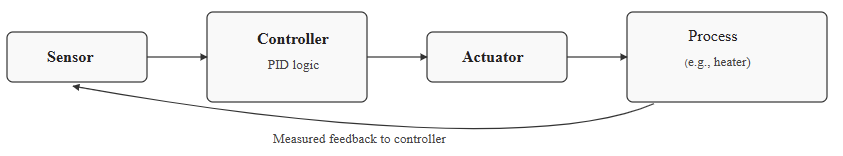
Data transmission and processing are the fundamental differences between these two protocols. Standard Ethernet sends individual data packets to each device. Each packet has addressing and configuration information (overhead). Network hardware like switches and routers manages this traffic. This strategy always introduces delays and variable latency (jitter).
Conversely, EtherCAT employs a real-time processing approach. The master device sends a single, large Ethernet frame (telegram) to all nodes. The network routes this telegram through all slave nodes. Each node reads its assigned input data from the passing frame.
It also writes its output data into the frame. All of this happens almost instantaneously, as the frame passes through the node. The frame then continues to the next device. It eventually returns to the master controller.
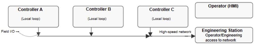
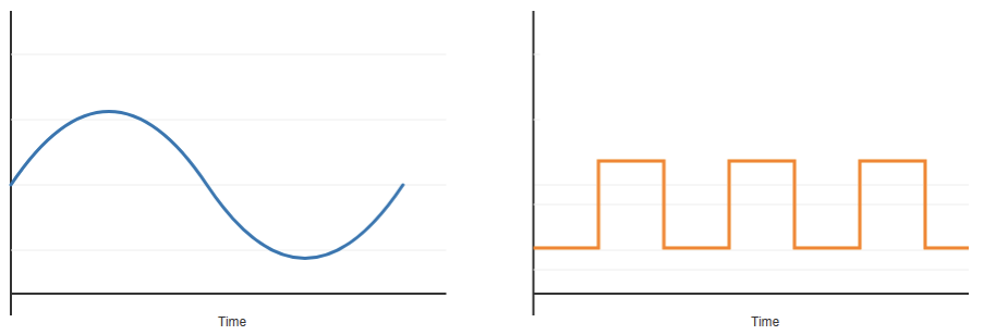
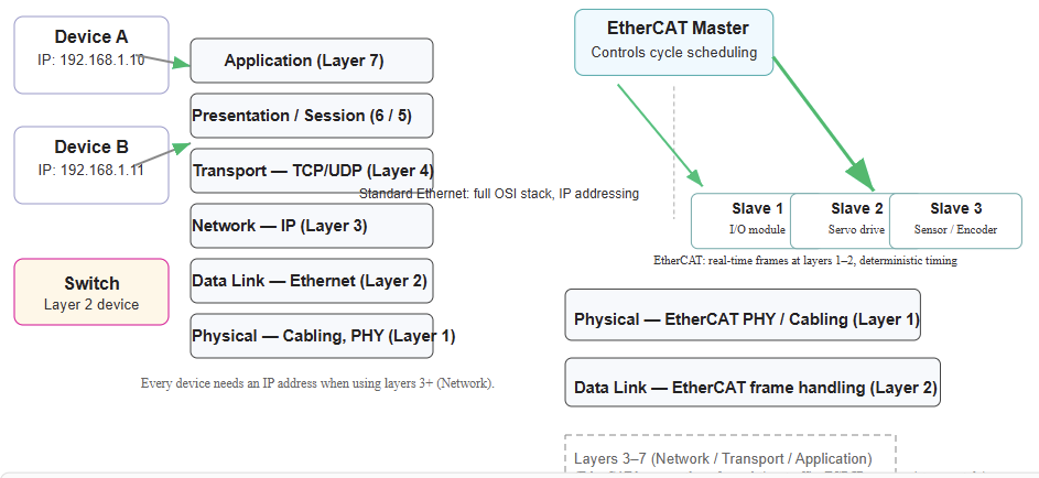
The figure below shows the difference between Standard Ethernet and EtherCAT.

Speed, Latency, and Determinism
Applications require data flows to occur in nanoseconds. The delay between when an instruction is received and when it executes, known as latency, is critical.
But latency is different from determinism, which is knowing exactly when an instruction will execute.
Standard Ethernet is suitable for the general public because it is faster, more reliable, and has high-speed communication.
It also has relatively high latency. Ethernet is more appropriate for less time-sensitive applications.
These can be as simple as performing testing, monitoring, and even implementing new software.
Ethernet performs with slower communication speed, lower bandwidth, and higher jitter than EtherCAT.
The main characteristics of EtherCAT are its speed and latency. EtherCAT’s on-the-fly processing decreases network latency. Each slave device introduces only a minimal delay (a few nanoseconds) to the whole process.
Data transmission is faster and has very low jitter. This deterministic nature is essential for real-time applications. These applications can be, for instance, multi-axis motion control and robotics.
In addition, EtherCAT is capable of achieving cycle times in the microsecond range. On the other hand, Ethernet mostly struggles to match this performance even with specialized hardware or protocols like Time-Sensitive Networking (TSN).
Network Architecture and Topologies
Standard Ethernet commonly uses a star topology. All devices connect to a central switch or hub. This format requires more cabling if devices are spread far apart.
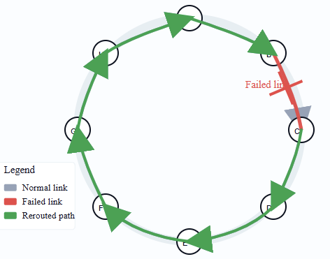
EtherCAT offers greater flexibility in topologies. It supports line, daisy-chain, star, and ring configurations. The line and daisy-chain options are very beneficial on a factory floor.
They simplify wiring and reduce the need for expensive managed switches. The ring topology also provides built-in redundancy. If a network link is broken, communication can continue in the other direction.
Hardware and Cost Considerations
Routers, network interface cards and switches, to mention a few, are hardware components that are inexpensive and readily available. Most standard computer equipment is Ethernet-ready from the outset.
EtherCAT requires specialized hardware. Slave devices must have an embedded EtherCAT Slave Controller (ESC) chip (often an ASIC).
This specialized hardware allows for the “processing-on-the-fly” method. This can make individual EtherCAT slave devices pricier than their standard Ethernet counterparts.
However, overall system costs can be lower. This is because fewer or no expensive managed switches are needed. Also, the reduced cabling needs in a line topology can save money.
Routers, network interface cards and switches, to name a few, are hardware components that are inexpensive and readily available.
Compatibility and Integration
Standard Ethernet is the friendly neighbor everyone knows. It’s built on technology that’s been around forever (open standards), so it plays nicely and fits right into just about any existing office or home network setup.
This familiarity makes it easy for IT professionals to manage. The one slight hassle? Every single device needs its own unique address (an IP address), which just means a bit more work to set up initially and keep track of over time.
EtherCAT is a bit more specialized. It’s built for speed and focus. It cuts out the middle layers of network communication, essentially bypassing all that extra chat you find in standard TCP/IP networking.
Think of it as a streamlined, direct path. This smart design is precisely why it can zip data around so much faster and more efficiently, making it perfect for those high-pressure, real-time jobs in a factory.
EtherCAT devices do not require an IP address. The device addresses itself logically based on its network position or through auto-discovery. EtherCAT frames have the capability to be encapsulated within a standard Ethernet frame.
This function allows it to be sent over an Ethernet network. The performance benefits are lost. The two are not directly compatible in terms of protocols.
Application Suitability: Which is Better?
The choice between these two communications protocols depends entirely on the project needs.
Standard Ethernet is ideal for non-time-critical applications. This includes data logging, remote monitoring, and linking the industrial network to the business network (IT/OT integration).
EtherCAT is the clear winner for performance-critical tasks. It is specifically designed for high speed and real-time synchronization control.
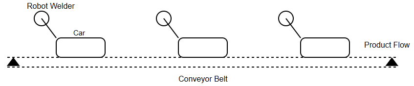
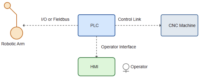
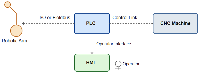
Typical applications include complex automated assembly lines and CNC machinery. Furthermore, it can be utilized in robotics and high-speed packaging machines.
The aforementioned processes utilize precise synchronization and rapid response times.
Key Takeaways: EtherCAT vs Ethernet
This article addressed the similarities and differences between Standard Ethernet and EtherCAT.
It provided clarification when it came to deciding which protocol is better for specific applications.
Actually, both protocols, Standard Ethernet and EtherCAT, use the same physical OSI level. But they are fundamentally different communication protocols. Standard Ethernet is versatile and cost-effective for general networking.
It is not inherently deterministic. EtherCAT is a specialized protocol for industrial automation.
It provides superior speed, extremely low latency, and highly deterministic performance. For synchronized motion control and high-performance industrial machines, EtherCAT is the better solution.
For less time-sensitive monitoring and general data exchange, standard Ethernet is more than sufficient and more flexible. The choice is a balance of complexity, cost and performance requirements.
FAQ: EtherCAT vs Ethernet
What is the main difference?
Ethernet is a general-purpose network, while EtherCAT is a real-time, high-performance industrial protocol.
Which one is faster?
EtherCAT. It processes data “on the fly,” giving very low latency.
Which one is better for real-time control?
EtherCAT. EtherCAT offers deterministic timing and precise synchronization.
Which one is easier to integrate with IT networks?
Ethernet. It uses standard TCP/IP and common network hardware.
Do devices need IP addresses?
Ethernet: yes.
EtherCAT: usually no (only the master may need one).
Which is better for data logging and monitoring?
Ethernet. Real-time performance isn’t required.
Which is better for robotics, CNC, and motion control?
EtherCAT. It’s designed for rapid, synchronized control.
Can both be used together?
Yes. EtherCAT for control, Ethernet for monitoring/IT.
Is EtherCAT more expensive?
Typically yes, because it requires EtherCAT-compatible hardware.
So which one is better overall?
Neither universally.
Use Ethernet for general communication; use EtherCAT for real-time industrial tasks.