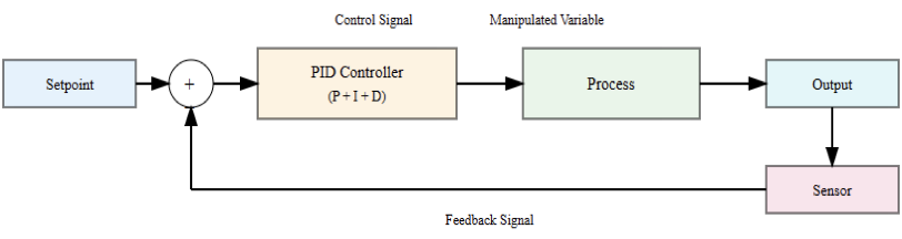
Industrial automation systems depend on reliable signal transmission mechanisms. Sensors continuously measure physical variables within dynamic process environments. These measured quantities must be transmitted accurately to controllers.
Two fundamental signal categories dominate industrial communication architectures. These categories are analog signals and digital signals.
Each signal type exhibits distinct characteristics and engineering implications. The selection between them influences system accuracy and reliability.
Noise immunity and scalability are also strongly affected. Modern facilities frequently integrate both signal types strategically.
Engineers must evaluate operational requirements before final implementation decisions.
This article reviews the principles of digital and analog signals, their technical differences, and performance characteristics within industrial automation systems. It furthermore studies the advantages, limitations, and practical applications.
Fundamentals of Industrial Signals
Industrial operations produce constantly changing physical events that need exact measurement.
Temperature, pressure, flow, and level vary depending on operating circumstances and process needs.
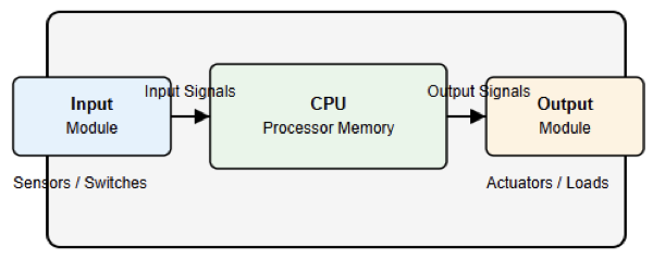
These physical characteristics are transformed into electrical representations ideal for transfer by sensors.
From cables or networks, these electrical signals move toward control equipment for analysis.
Vibration, extremes in temperature, and electromagnetic interference notwithstanding, signal integrity has to be kept.
Installations with big motors and switching equipment are usually subject to electromagnetic interference.
Correct grounding, shielding, and routing techniques greatly lower unwelcome signal distortions.
The consistency of the signal and the general reliability of the measurement are also affected by transmission distance.
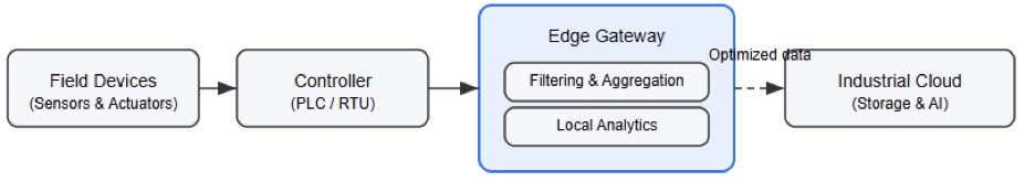
Raw sensor signals are made ready for precise controller reading by signal conditioning modules.
Filtering, amplification, and isolation methods increase consistency and shield delicate components.
Usually categorized as analog or digital, signals in industrial settings are. Every category has particular interpretation traits and transmission behavior influencing system design.
Analog Signals in Industrial Automation
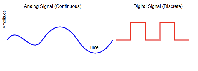
Analog signals vary continuously over time and proportionally represent measured quantities.
Their amplitude directly corresponds to the magnitude of the physical variable being monitored.
In industrial practice, voltage or current levels change proportionally with process conditions.
One of the most widely adopted standards is the 4–20 milliampere current loop. This current loop configuration offers excellent immunity to electrical noise and voltage drops. Voltage-based analog signals typically range between zero and ten volts in control systems.
Analog transmission allows representation of virtually infinite intermediate values within a defined range.
Sensor quality and internal conversion precision within the controller directly influence measurement resolution.
Still, attenuation and environmental effects can attack analog signals over great distances.
Temperature variation and cable resistance may introduce small but significant measurement errors.
Signal isolators and repeaters help mitigate ground loop problems and improve reliability. Despite certain limitations, analog signals remain dominant within process industries requiring continuous measurement.
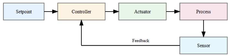
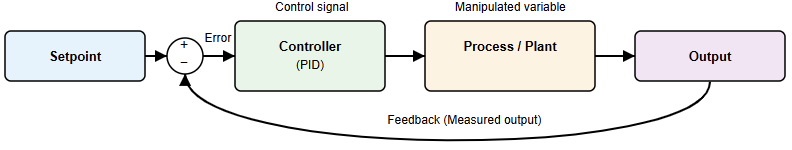
Continuous control loops benefit greatly from proportional signal representation and smooth feedback behavior.
Digital Signals in Industrial Automation
Digital signals operate using discrete states, typically representing binary conditions of zero or one.
A digital input may indicate whether a motor is running or stopped. Another digital signal might confirm that a valve has reached its fully open position.
Unlike analog signals, digital values change abruptly between defined logical levels. This discrete behavior makes them inherently less susceptible to gradual signal degradation. Minor electrical noise rarely alters logical states when thresholds are properly defined.
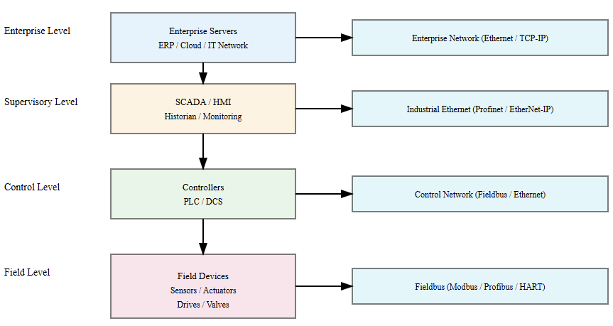
Digital communication in industrial automation extends beyond simple on-off signaling. Fieldbus and industrial Ethernet protocols transmit structured digital data packets efficiently.
Examples include Modbus, Profibus, and Ethernet-based industrial communication systems.
These protocols encode multiple variables, diagnostics, and device parameters simultaneously.
Error detection mechanisms, checksums, and sequence validation improve transmission reliability significantly.
Digital systems also support advanced diagnostics and device identification capabilities. Discrete signaling simplifies fault detection, troubleshooting, and system expansion within complex installations.

Signal Conversion and Interface Considerations
Industrial controllers must interpret both analog and digital signals reliably. Analog-to-digital converters transform continuous values into numerical representations for processing. Digital-to-analog converters generate proportional output signals for actuators and drives.
Programmable controllers typically contain integrated conversion modules for signal handling.
Sampling rate strongly influences the accuracy of analog measurements in dynamic processes.
Higher sampling frequencies capture rapid variations more effectively and reduce aliasing errors.
Quantization introduces small approximation differences that depend on converter resolution.
Resolution is determined by the number of bits used in conversion hardware. A twelve-bit converter provides moderate precision suitable for many applications.
Greater bit depth increases measurement granularity and control sensitivity. Signal scaling aligns raw digital counts with meaningful engineering units for operators.
Calibration procedures ensure long-term measurement stability and regulatory compliance. Interface design, therefore, plays a critical role in overall automation system performance.
Noise Immunity and Reliability
Industrial environments contain significant electromagnetic disturbances generated by heavy equipment.
Large motors, variable frequency drives, and switching devices produce electrical interference. Analog signals can pick up induced voltages along improperly shielded cables.
Shielded twisted pair wiring significantly reduces electromagnetic coupling effects. Current loop systems inherently provide superior noise rejection compared to voltage signals. Digital signals resist minor amplitude distortions due to defined logical thresholds.
However, severe interference may corrupt digital data packets during transmission. Error detection algorithms quickly identify corrupted messages and request retransmission. Redundant communication paths further increase network availability and resilience.
Grounding strategy remains critically important for both analog and digital installations. Isolation barriers prevent hazardous potential differences and equipment damage.
Reliability ultimately depends on disciplined engineering practices and proper installation procedures.
Accuracy and Resolution Comparison
Analog systems theoretically allow infinite resolution within a specified measurement range.
In practice, achievable accuracy depends on sensor characteristics and conversion hardware limitations.
Component aging and environmental stress may gradually reduce measurement precision.
Digital sensors often incorporate internal signal processing and compensation algorithms. These devices may provide stable outputs with reduced drift over time.
Resolution in digital systems becomes defined by word length and scaling configuration. Higher resolution enables finer control adjustments and improved process optimization.
However, excessive precision may exceed realistic process requirements and increase cost unnecessarily.
Engineers must carefully balance accuracy expectations with economic considerations. Calibration intervals significantly influence long-term confidence in measurement data.
High reliability is attainable with either analog or digital architectures if properly designed. Selection should therefore reflect operational demands and performance objectives realistically.
Transmission Distance and Infrastructure
Long-distance transmission presents challenges for certain analog voltage signals. Signal drop increases proportionally with cable length and conductor resistance.
Current loop systems maintain stable measurement integrity across longer distances effectively.
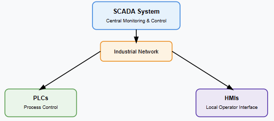
Digital communication networks support distributed architectures spanning extensive industrial sites.
Industrial Ethernet enables reliable data exchange across large facilities and remote areas.
Fiber optic links eliminate electromagnetic interference concerns in harsh environments.
Infrastructure cost strongly influences overall system architecture decisions. Existing plant wiring may favor retention of analog loops during modernization efforts. New installations frequently adopt digital networks for scalability and diagnostics.
Hybrid systems often integrate both approaches to optimize performance and cost. Scalable architecture supports sustainable long-term investment strategies.
Integration with PLCs
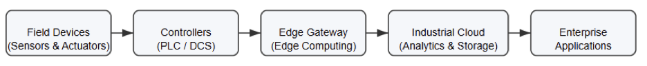
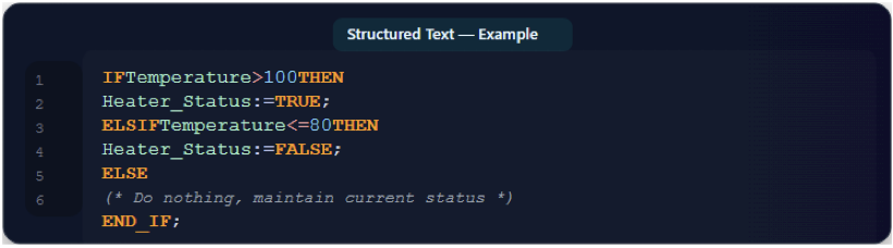
Programmable logic controllers interpret industrial signals using deterministic execution cycles.
Manufacturers such as Siemens provide modular input and output interface cards for flexibility.
Another major automation supplier is Rockwell Automation, offering comprehensive controller platforms.
Analog input modules precisely measure current or voltage from field instruments. Digital input modules detect discrete device states, such as switches and relays. Output modules drive actuators, solenoids, and motor contactors accordingly.
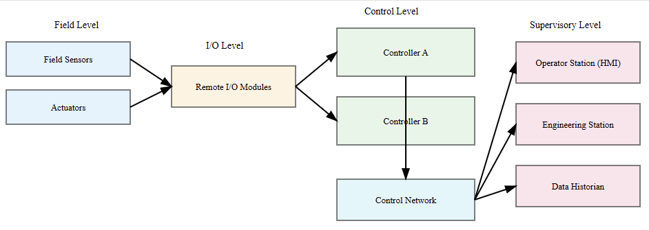
Controller scan cycles process digital states extremely rapidly and predictably. Analog values require sampling, scaling, and filtering before logical evaluation. Distributed input systems reduce centralized wiring complexity and installation cost.
Networked architectures enhance diagnostic visibility and configuration flexibility significantly.
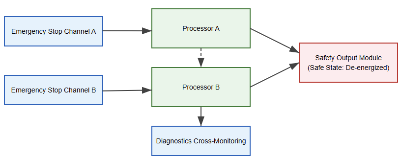
Modern controllers often combine standard control and safety functions within integrated platforms.
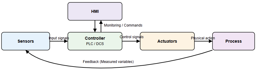
Effective signal management remains fundamental to automation system reliability and performance.

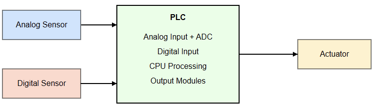
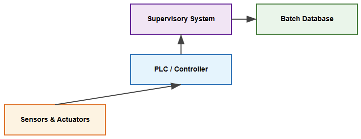
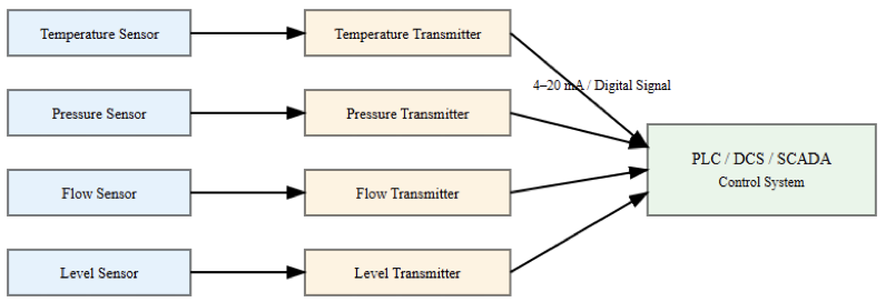
PLC Signal Integration Architecture
Applications Across Industrial Sectors
Analog Applications
Process industries such as chemical manufacturing rely heavily on analog instrumentation.
Flow transmitters provide continuous feedback to closed-loop control systems. Pressure monitoring ensures safe equipment operation under varying load conditions.
Digital Applications
Digital signals supervise pump status, interlocks, and alarm conditions reliably. Power generation facilities integrate extensive measurement networks for turbine control. Oil and gas installations deploy advanced distributed control architectures.
Mixing Applications
Food processing lines combine continuous measurement with discrete packaging machinery control.
Water treatment facilities monitor the level continuously. They also constantly supervise turbidity and chemical dosing.
Each industry carefully balances analog and digital implementation according to operational needs.
Maintenance teams analyze both continuous trends and discrete event logs. Operational safety and productivity depend on accurate signal interpretation.
These diverse applications demonstrate the complementary nature of both signal types.
System Design Strategy and Hybrid Approaches
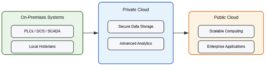
Modern automation strategies rarely rely exclusively on one signal category. Hybrid architectures combine analog measurement reliability with digital communication flexibility. Critical feedback loops often maintain analog proportional control for stability.
Supervisory systems exchange information and diagnostics through digital networks. Gradual modernization strategies minimize disruption within operating facilities. Legacy analog instruments frequently coexist with intelligent digital field devices.
Planning for migration guarantees compatibility with upcoming technical breakthroughs. Engineers assess performance goals, lifecycle cost, and maintainability demands.
Traceability and regulatory compliance are aided by configuration management and documentation.
Balanced system design improves operational resilience and long-term scalability. Effective integration ultimately determines overall automation success.
Conclusion
This article introduced the principles of digital and analog signals in industrial automation.
It explained their characteristics, operational behavior, integration considerations, and practical applications across diverse industrial sectors.
Analog signals provide continuous proportional representation of changing process variables.
Digital signals deliver discrete states and structured communication with advanced diagnostics.
Each approach offers distinct strengths regarding noise immunity, scalability, and system integration.
Environmental conditions and transmission distance significantly influence performance outcomes.
Programmable controllers integrate both signal types within cohesive architectures. Hybrid implementations often achieve an optimal balance between reliability and flexibility.
Engineers must align the signal strategy with the documented process requirements carefully.
Thoughtful planning ensures dependable, efficient, and future-ready automation infrastructure.
Understanding these distinctions enables informed technical decisions and improved industrial system performance.
FAQs: Digital vs Analog Signals in Industrial Automation
In industrial automation, what is an analog signal?
Process values are represented by an analog signal that changes constantly and proportionally.
Automation systems define a digital signal as
Information is sent through discrete binary states in a digital signal.
What kind of signal gives greater noise immunity?
Usually, digital signals are more resilient to little electrical disturbance are digital signals.
Why are 4–20 mA loops so widely used?
Their robust noise immunity enables dependable long-distance communication.
Can both signal kinds function within one control system?
Most modern automation systems do so efficiently.