Fire safety protects lives and property. Fire alarm systems provide early warnings. These systems detect dangerous fire conditions. They alert occupants using clear signals. Early alerts reduce panic during emergencies.
They also support faster building evacuation. Fire alarms operate across many environments, such as the home, which uses simple detection devices. Offices use networked alarm panels, while factories use robust industrial systems.
Each location presents unique fire risks. Proper design matches specific hazards. Regulations guide correct system selection. Standards ensure reliability and performance, and maintenance keeps systems ready always.
Testing confirms correct alarm operation, and training helps occupants respond correctly. Fire alarms integrate with suppression systems.
They also connect with monitoring centers. Modern systems include smart technologies.
This article explains fire alarm fundamentals. It covers components, types, and operation. It also discusses design, installation, and maintenance.
What Is a Fire Alarm?
A fire alarm is a safety system because it detects fire-related conditions. These conditions include smoke and heat.
Some systems detect flame radiation. Detection triggers audible and visual alerts, and then the alerts warn occupants of danger.
Signals can also notify responders. The system works automatically or manually.
Automatic devices sense environmental changes, while manual devices allow human activation.
Both methods increase overall safety. Fire alarms operate continuously when powered, so backup power should ensure operation during outages.

Purpose of Fire Alarm Systems
Fire alarms exist to save lives. Early detection prevents severe fire spread. Quick alerts support timely evacuation. Property damage is also minimized. Alarms guide occupants toward safe exits.
They reduce confusion during emergencies. Systems support coordinated emergency response. They notify fire brigades quickly, shortening response time significantly. Faster response reduces casualties and losses.
Main Components of a Fire Alarm
Fire alarm systems include several components. Each component performs a specific role.
Together, they ensure reliable operation. Components communicate through wired networks. Nevertheless, wireless options also exist today.

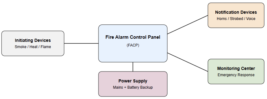
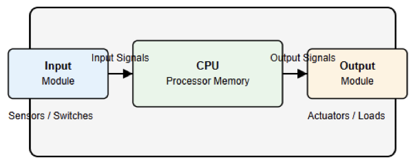
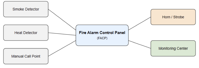
Fire Alarm Control Panel
The control panel is the system’s brain. It receives signals from devices and processes detection information quickly. The panel activates alarms when required. It also monitors system faults.
Status indicators show system conditions. Panels store event history data, while advanced panels support network integration.
Initiating Devices
Initiating devices detect fire conditions. Flame detectors sense fire radiation while smoke detectors sense smoke in the air.
Also, heat detectors sense temperature increases. Manual call points allow manual activation.
Each device suits specific environments. Hence, correct selection ensures accurate detection.
Notification Appliances
Notification appliances alert building occupants. Audible devices include horns and bells. Visual devices include flashing strobes.
On the other hand, voice alarms provide spoken instructions. Alerts must be clearly recognizable, and make sure that sound levels must follow safety standards. Visual alerts support hearing-impaired occupants.
Power Supply and Backup
Fire alarms require continuous power. The main power comes from the building supply. Backup batteries support outage operation.
Some systems use generators additionally. Backup duration follows code requirements. Reliable power ensures constant protection.
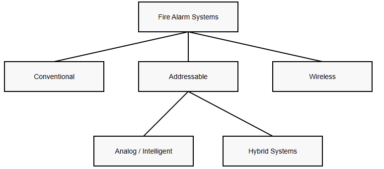
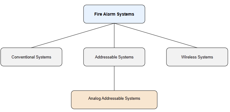
Types of Fire Alarm Systems
Fire alarm systems vary by complexity. Selection depends on building size. Risk level also influences choice. Codes specify acceptable system types.
Conventional Fire Alarm Systems
Conventional systems divide buildings into zones. Each zone connects multiple detectors. Alarms indicate the affected zone only, and the exact device location remains unknown.
These systems are cost-effective. They are suitable for small buildings, and wiring requirements are relatively simple.
Addressable Fire Alarm Systems
Addressable systems assign unique device addresses. Each detector communicates individually, and in this way, panels identify exact alarm locations.
Maintenance becomes easier and faster. Wiring uses loops instead of zones. These systems suit larger buildings, and they provide advanced diagnostic features.
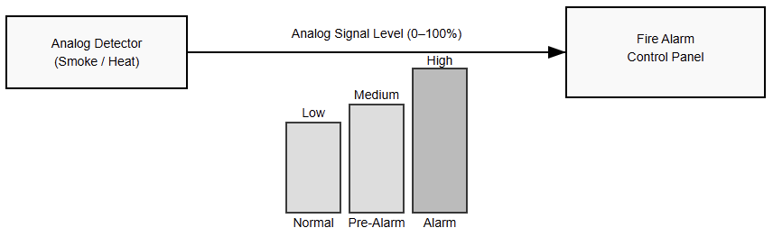
Analog Addressable Systems
Analog addressable systems measure sensor values. The panel analyzes environmental changes.
It determines alarm thresholds dynamically, and false alarms are reduced significantly. Sensitivity can be adjusted remotely. These systems offer superior reliability.
Wireless Fire Alarm Systems
Wireless systems use radio communication. These devices communicate without physical cables. In this type, installation time is significantly reduced.
These systems suit heritage buildings. Battery management is critically important. Signal reliability must be carefully verified.

Detection Technologies
Different technologies detect different fire characteristics. Selection depends on environmental conditions. Proper choice minimizes nuisance alarms.
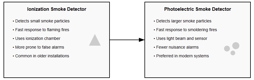
Smoke Detection
Smoke detectors identify combustion particles. Ionization detectors sense small particles. Photoelectric detectors sense larger particles. Photoelectric types reduce false alarms. Smoke detection provides early warnings.
Heat Detection
Heat detectors sense temperature increases. Fixed temperature detectors activate at thresholds.
Rate of rise detectors sense rapid changes. Heat detectors suit harsh environments. They resist dust and humidity effects.
Flame Detection
Flame detectors operate by detecting ultraviolet and infrared flame radiation. Detection is extremely fast. These detectors suit high-risk areas. Fuel storage facilities use them.
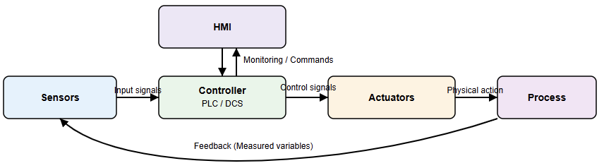
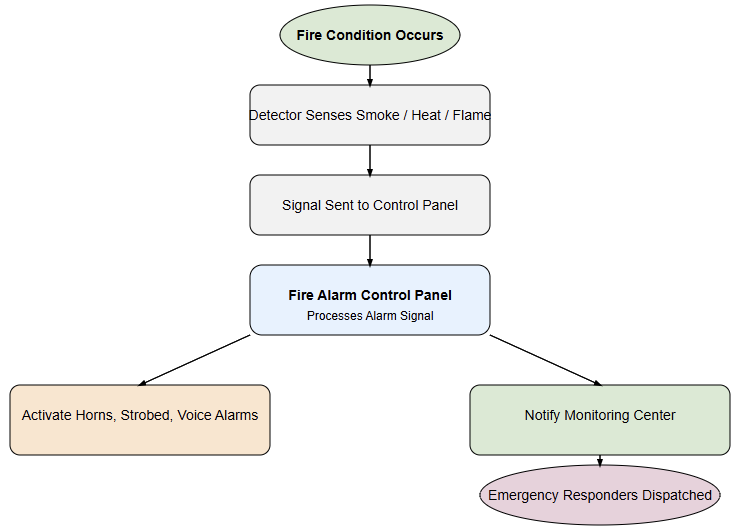
Fire Alarm System Operation
Fire alarm operation follows a sequence. Detection devices sense abnormal conditions. Signals travel to control panels. Panels verify alarm conditions.
Notification appliances activate immediately. Occupants receive clear warnings. Alarm signals are received by monitoring centers. Emergency response teams are promptly dispatched.

Integration With Other Systems
Fire alarms integrate with building systems. Elevators return to safe floors. HVAC systems shut down automatically.
Fire doors close to contain smoke. Sprinkler systems activate when required. Integration improves overall safety performance.
Design Considerations
Proper design ensures effective protection. Designers assess building occupancy types. Fire load and layout are analyzed.
Detector spacing follows code rules. Notification coverage must be adequate. System zoning improves emergency response.
Installation Practices
Installation must follow approved drawings. Certified technicians perform installations. Cable routing avoids electrical interference. Devices are mounted at the correct heights. Labels identify circuits and zones clearly.
Testing and Commissioning
Testing verifies correct system operation. Each device is tested individually. Alarm signals are verified carefully.
Fault conditions are simulated intentionally. Commissioning documentation records results clearly.
Maintenance and Inspection
Long-term reliability is always assured by performing regular maintenance. Inspections follow scheduled intervals.
Batteries are tested and replaced. Detectors are cleaned periodically. Records document maintenance activities thoroughly.
Standards and Regulations
Fire alarm systems follow safety standards. Codes specify design and installation. Compliance ensures legal operation. Authorities review system approvals because regular audits ensure ongoing compliance.
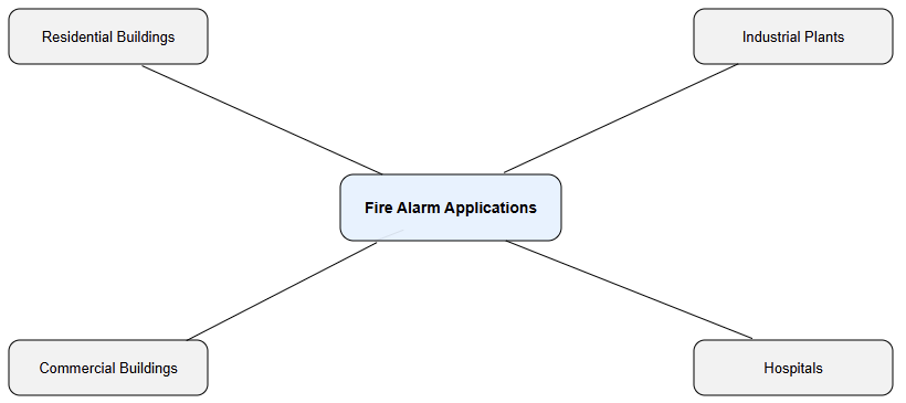
Common Fire Alarm Applications
The main applications are:
- Fire alarms protect various environments.
- Residential buildings use simple systems.
- Commercial buildings use addressable systems.
- Industrial plants use specialized detectors.
- Hospitals use voice evacuation systems.
Each application demands tailored solutions.

Pros and Cons of Fire Alarm Systems
Advantages
- Fire alarms provide early fire detection.
- They significantly reduce loss risks.
- Occupant safety is greatly improved.
- Property protection costs are minimized.
- Insurance benefits may also apply.
Disadvantages
- Fire alarm systems can produce false alarms.
- False alarms cause unnecessary evacuations.
- They may reduce occupant response seriousness.
- Poor maintenance affects system reliability.
- Dust and humidity trigger nuisance alarms.
- Installation costs can be relatively high.
Limitations and Challenges
Fire alarms have certain limitations. False alarms cause occupant complacency. Poor maintenance reduces system reliability. Improper design causes coverage gaps. Training helps reduce these issues.
Future Trends in Fire Alarms
Technology continues to improve fire alarms. Smart sensors use advanced algorithms. IoT connectivity enables remote monitoring.
Data analytics improves alarm accuracy. Integration with building management increases efficiency.
Key Takeaways: What Is a Fire Alarm?
This article examined how life and property can be protected using fire alarm systems. This action is through early detection, dependable notification, and coordinated emergency response. Fire alarm systems remain essential to modern fire safety.
This is done by enabling timely alerts and supporting safe evacuation. These systems help reduce panic during emergencies. They also assist emergency teams in responding faster.
Core elements include control panels, initiating devices, notification appliances, and reliable backup power supplies. Each component plays a critical safety role.
System configurations range from conventional to analog addressable and wireless designs, serving different environments and risk levels.
Effective performance depends on proper design, correct installation, and system integration.
In addition, it relies on regular testing and consistent maintenance. Finally, to ensure long-term reliability and operational readiness, all practices mentioned above must be followed.
FAQ: What Is a Fire Alarm?
What is a fire alarm system?
A fire alarm system is a group of devices designed to detect smoke, heat, flame, or other fire-related threats. It then alerts occupants and often emergency responders to ensure quick evacuation and safety.
What is the main purpose of a fire alarm?
The primary goal is to warn people early about a fire so they can safely leave the building. Fire alarms also support emergency response and can trigger other safety systems.
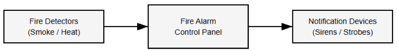
How does a fire alarm system work?
Detectors sense fire indicators (smoke, heat, flame). Signals go to a control panel. The panel then activates audible and visual alarms and may alert monitoring services.
What devices make up a fire alarm system?
Fire alarms include detectors (smoke, heat, flame), manual pull stations, control panels, and notification devices like horns or strobes.
Are fire alarms automatic or manual?
They can be both automatic (detect environmental changes) and manual (activated by a person).