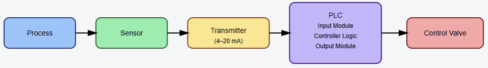
Industrial automation systems depend on clean electrical environments. Programmable Logic Controllers operate within electrically noisy industrial facilities.
High-power equipment generates interference affecting sensitive control electronics.
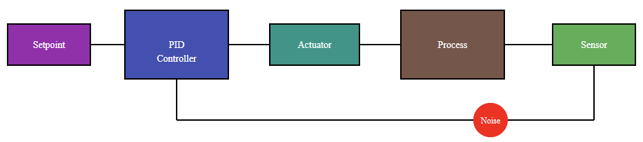
Grounding and shielding practices protect control systems from disturbances. Poor grounding may cause erratic controller behavior to occur unexpectedly. Electrical noise can corrupt analog and digital signals.
Improper shielding may introduce intermittent communication failures. These issues often appear during commissioning or startup phases. System reliability depends heavily on proper installation practices.
Careful design reduces susceptibility to electromagnetic interference significantly. Effective grounding ensures stable reference potentials across devices. Shielding prevents unwanted noise coupling into signal conductors.
Engineers must understand both principles and implementation techniques. This article reviews PLC grounding and shielding best practices for reliable industrial automation systems.
Fundamentals of Electrical Grounding
Grounding establishes a reference potential for electrical systems. It provides a controlled path for fault currents.
Proper grounding protects equipment and personnel from hazards, and that is why, in control systems, grounding also stabilizes signal references.
Without stable references, measurement accuracy degrades considerably. Grounding systems typically connect to plant earth grids.
The earth grid dissipates fault energy safely underground. Separate protective and signal grounds are often recommended.
A well-engineered thermal design reduces thermal stress on components. As a result, insulation integrity is preserved over time. By this means, signal grounding aims to minimize electrical noise interference.
Incorrect bonding may create unintended circulating currents. These currents are commonly known as ground loops.
Ground loops introduce unwanted voltage differences between devices. Such differences distort low-level analog signals. Understanding grounding topology is therefore critically important.
Types of Grounding in PLC Systems
PLC installations typically include several grounding categories. Protective earth grounding ensures enclosure safety compliance. Functional grounding supports the stable operation of electronics.
Instrument grounding maintains reference integrity for measurements. Shield grounding reduces electromagnetic interference pickup significantly.
Each grounding type must be clearly identified. Integrating both purposes without proper design can negatively affect system stability.
Protective earth conductors bond metallic enclosures to ground to limit dangerous touch voltages during insulation breakdown. Functional grounding connects controller reference points appropriately.
Manufacturers often specify recommended grounding terminals clearly. Instrument grounds are commonly tied at single points.
Single-point grounding minimizes circulating loop currents. Multiple-point grounding may be suitable for high frequencies. Engineers must evaluate frequency content carefully.
Understanding Electromagnetic Interference
Industrial environments contain numerous interference sources. Variable frequency drives generate high-frequency switching noise.
Large motors produce transient voltage spikes frequently. Welding equipment creates substantial electromagnetic disturbances. Even fluorescent lighting can emit electrical noise.
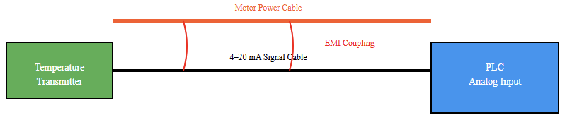
Electromagnetic interference couples through conduction or radiation. Conducted noise travels along power and signal conductors.
Radiated noise propagates through surrounding electromagnetic fields. Sensitive PLC inputs can detect these disturbances inadvertently.
Analog signals are especially vulnerable to interference. Low-voltage signals amplify measurement inaccuracies significantly.
Understanding interference mechanisms supports better mitigation strategies. Shielding blocks radiated fields from reaching conductors.
Grounding diverts conducted noise safely away. Both methods must operate together effectively.
Shielding Principles for Signal Integrity
Shielding uses conductive barriers around signal conductors. These barriers intercept external electromagnetic fields.
The shield then directs interference toward the ground. There is no doubt that proper termination is essential for effectiveness.
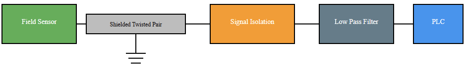
Braid or foil shields are often included in signal cables. Twisted pair construction further reduces magnetic coupling. Twisting ensures balanced noise cancellation characteristics. Shield continuity must remain intact across junctions. Broken shields compromise protection immediately.
Single-ended shield grounding is common for analog signals. One end connects to designated ground reference points.
The opposite end remains isolated to prevent loops. High-frequency environments may require both ends grounded.
Such decisions depend on installation conditions. Engineers must follow manufacturer recommendations carefully.

Integrated PLC Grounding and Shielding Architecture
Cable Routing and Segregation Practices
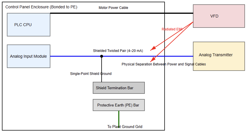
Physical separation reduces noise coupling dramatically. Power cables should not run parallel with signals.
When separation cannot be avoided, ensure sufficient spacing is maintained. Crossing cables at right angles minimizes interference.
Separate trays for power and instrumentation are advisable. Metallic conduits can provide additional shielding benefits.
However, improper bonding may negate advantages entirely. Cable glands must maintain shield continuity reliably.
Control panels require organized internal routing practices. High-current wiring should remain isolated.
Analog input cables deserve dedicated routing channels. Good layout practices simplify future maintenance significantly.
Grounding and Shielding Inside Control Panels
Control panels represent concentrated electrical environments. Multiple devices share limited physical space.
Proper bonding of panel backplates is necessary. All metallic components should connect to protective earth.
DIN rails must maintain reliable ground continuity. Paint removal may be required under mounting points. Grounding bars provide centralized bonding locations.
Each ground conductor should terminate individually. Stacking conductors under one screw is discouraged.
Analog module commons should follow manufacturer guidance. Shield drains often terminate on dedicated bars.
Avoid connecting shields directly to random terminals. Consistent labeling supports troubleshooting efficiency.
Avoiding Ground Loops in PLC Installations
Ground loops occur when multiple return paths exist. Slight potential differences drive unintended currents.
These currents introduce measurable signal offsets. Analog inputs may fluctuate unpredictably.
Single-point grounding minimizes loop formation risks. All reference returns converge at one location.
Remote panels require careful bonding strategies. Communication networks require special grounding considerations.
Isolated input modules can reduce loop susceptibility. Signal isolators break direct electrical continuity.
Fiber optic communication eliminates conductive paths. Engineers must evaluate cost and complexity carefully.
Power Supply Considerations
Stable power supplies support reliable PLC performance. Switching supplies may introduce high-frequency noise. Proper filtering reduces conducted interference effectively.
Power supply negatives often tie to the system ground. However, unnecessary bonding may create loops.
Follow the manufacturer’s wiring diagrams precisely. Separate power circuits for analog modules are beneficial.
Uninterruptible power supplies enhance system resilience. They also require appropriate grounding arrangements.
Surge protection devices must connect to low impedance grounds. High impedance paths reduce protective effectiveness significantly.
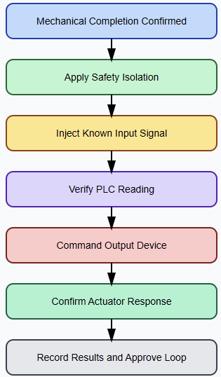
Verification and Testing Practices
Installation quality must be verified systematically. Continuity tests confirm protective grounding integrity. Insulation resistance tests detect wiring defects.
Oscilloscopes can reveal unexpected noise components. Monitoring analog signals under load is useful. Comparison against baseline values identifies anomalies.
Commissioning documentation should record grounding connections clearly. Future maintenance benefits from detailed records.
Periodic inspection ensures long-term reliability. Corrosion or loose connections degrade performance gradually.
Best Practice Design Recommendations
Begin grounding design during early engineering phases. Incorporate plant grounding grid information into drawings. Define a clear separation between grounding categories.
Specify shielded twisted pair cables for analog loops. Identify shield termination points on schematics explicitly. Provide dedicated grounding bars within each panel.
Train installation technicians on correct termination methods. Conduct design reviews focusing on noise susceptibility. Also, collaborate with equipment vendors when uncertainties arise.
Comprehensive planning reduces troubleshooting after energization. Good grounding rarely attracts attention during operation.
Poor grounding immediately reveals itself through instability. Engineers should treat grounding as foundational infrastructure.
Conclusion
This article introduced PLC grounding and shielding best practices for industrial automation installations.
It explained grounding fundamentals and interference mechanisms affecting sensitive control electronics.
The discussion described shielding methods, cable routing practices, and panel bonding requirements. Strategies for avoiding ground loops and ensuring stable references were outlined.
The conversation covered cable routing techniques, panel bonding criteria, and shielding methods. Plans for preventing ground loops and guaranteeing stable references were presented.
Additionally stressed were power source factors and verification processes. Good shielding and grounding lower electrical noise, boost operational dependability, and raise signal quality.
Using ordered design and installation techniques helps engineers to safeguard PLC systems from disruption and guarantee safe, reliable, and consistent industrial control performance.
FAQs
Why is grounding necessary in a PLC system?
Grounding gives a consistent reference and lowers electrical noise that might interfere with PLC signals.
In PLC wiring, what purpose does shielding serve above all other goals?
By protecting sensitive signal wires, shielding prevents electromagnetic interference from compromising them.
Should cable shields be grounded at both ends?
Grounding the shield at one end helps most low-frequency PLC signals avoid damaging ground loops.
On PLC cables, where should shield grounding take place?
End the shield at the control panel or PLC end to a common ground point.
What a ground loop is and why it must be avoided
Noise is an unintended current flowing between several ground potentials, a ground loop.
Does separating cables physically matter?
Yes, separate or cross power and signal cables at right angles to reduce noise.
Within control panels, how should grounding and shielding be managed?
All metallic components, shields, and protective earth points have to link to a centrally located grounding bar.
In PLC networks, does grounding help Ethernet communication?
Proper grounding and shielding guarantee fewer communication mistakes and lower noise.
Should power grounds be combined with analog and digital grounds?
No, separate signal grounds from power grounds until they converge at the primary ground point.