Industrial Sensor Types

Modern industrial systems need sensors to track, control, and so improve processes. Sensors serve as the main interaction between control systems and the physical world. From chemical plants and smart factories to power plants and manufacturing lines. 

They convert physical elements like pressure and flow into valuable electrical signals. They do so to temperature as well as position. Without reliable sensors, automation, safety, and efficiency would not be achievable. 

Sensor technology is always growing in accuracy and dependability. Also, networking industries embrace more and more degrees of digitization. Plus, Industrial Internet of Things (IIoT).

Engineers, technicians, and decision makers are engaged in industrial automation. In order to know the several kinds of industrial sensors and how they operate. 

The main kinds of industrial sensors are examined in this article. Also clarifies their functioning principles and covers their frequent uses.  

Temperature Sensors 

Among the most frequently measured parameters in industrial procedures is temperature.

Applications include chemical reactors and food processing. It may include HVAC systems and boilers. 

Without forgetting, furnaces also employ temperature sensors. Thermocouples and resistance temperature sensors (RTDs) are among the most commonly used industrial temperature sensors. Also, without forgetting the thermistors. 

Working on the Seebeck effect, thermocouples produce a voltage. This phenomenon occurs when two different metals are linked.

Then, both were introduced to a temperature differential. Suitable for demanding industrial conditions, they are strong, cheap, and able to measure very high temperatures. 

Usually consisting of platinum, RTDs measure temperature by relating resistance variations to temperature.

Often employed in precise industrial uses, they provide great accuracy and long-term stability.

Usually employed where quick reaction is needed. Thermistors have excellent sensitivity over a small temperature range. 

Pressure Sensors 

Critical in sectors including oil and gas and power production, pressure sensors have an important function.

Include in hydraulics and process manufacturing. These detectors translate the force applied by a liquid or gas into an electrical signal. Piezoresistive, capacitive, and strain-gauge-based sensors are among the most used. 

Piezoresistive pressure sensors depend on the shift in electrical resistance of a semiconductor material under mechanical stress. Their small size and great sensitivity make them quite popular.

Particularly well-suited for low-pressure measurements. These sensors record variations in capacitance brought on by diaphragm deflection under pressure.

Strain-gauge pressure sensors provide dependability and robustness in industrial applications.

They achieve this by detecting deformation using bonded or deposited strain gauges on the diaphragm. 

Flow Sensors

Monitoring fluids and gases in pipelines totally depends on flow sensors. Also, inspecting cooling systems and chemical reactions.

They guarantee safety, energy efficiency, and appropriate material distribution. Differential pressure flow meters and turbine flow meters are among industrial flow sensors. Also, it includes electromagnetic flow meters and ultrasonic flow meters. 

Differential pressure flow meters, like venturi tubes and orifice plates deduce flow rate from pressure variations over a barrier.

Based on the rotational speed of a turbine positioned in the fluid stream, turbine flow meters determine flow. 

Operating according to Faraday’s law of electromagnetic induction. This makes electromagnetic flow meters best suited for conductive liquids.

Without physical touch with the fluid, ultrasonic flow meters measure flow velocity using sound waves. Therefore, fit in corrosive or hygienic uses. 

Level Sensors 

Level sensors register the height or volume of solids and fluids in reservoirs, silos, and tanks.

They find application in the mining sector as well as in chemical storage. Also in food processing and water purification. Contact or non-contact forms of level sensors exist. 

Float switches and capacitive probes, which physically contact the substance being measured, are among contact-level sensors.

Wave reflection methods let non-contact level sensors, like radar and ultrasonic sensors, measure distance. 

Because of their capacity to function precisely under harsh temperature, pressure, and vapor circumstances, radar level sensors are rather well-known in current industrial factories.

Material type, tank shape, and environmental conditions all influence the selection of the right level sensor. 

Proximity and Position Sensors

Detecting the presence or absence or position of objects in industrial automation systems depends on these types of sensors.

Conveyor systems and robotic arms all depend on them. Plus, as machine tools and packaging equipment.

In addition, inductive and capacitive are among the most used. Last but not least, photoelectric and ultrasonic sensors are in the list. 

Utilizing electromagnetic fields, inductive proximity sensors identify metallic objects. These sensors are very resistant to vibration.

They do so with dust and oil as well. Capacitive proximity sensors can detect both metallic and non-metallic objects. It may include liquids and plastics

Long sensing ranges and quick reaction times characterize photoelectric sensors. They do so by using light beams to detect object presence.

In motion control systems, position sensors offer exact displacement readings. A good example is linear variable differential transformers (LVDTs). 

Velocity and Motion Sensors 

Rotational or linear motion in motors, conveyors, and spinning equipment is tracked by speed and motion sensors.

Feedback control, predictive maintenance, and safety systems all depend on these sensors. 

Most often found speed sensors in industrial situations are encoders and tachometers. High-resolution location and speed information from optical encoders results from light patterns that produce pulses mirroring movement. 

Magnetic encoders resist difficult situations and pollution more so than their counterparts.

Often used in motor control applications, tachometers measure rotational speed directly. Motion sensors allow for early intervention by detecting aberrant operating conditions like overspeed or mechanical wear. 

Gas and Chemical Sensors

The procedure of ensuring process control and environmental compliance depends on gas and chemical sensors.

Plus, ensuring the safety of professional personnel. Plants like chemical plants and laboratories use them extensively.

Also, mining projects depend on these sensors.  Common gases like oxygen and carbon monoxide are detected by these sensors. Without forgetting hydrogen sulfide, volatile organic chemicals are in the list. 

Offering great sensitivity and selectivity, electrochemical gas sensors produce a current depending on gas concentration.

Frequently used for hydrocarbon detection, infrared gas sensors measure the gas absorption of infrared light. 

When exposed to particular gases, semiconductor gas sensors alter their electrical resistance.

The target gas kind, concentration range, and environmental conditions determine the choice of the right gas sensor. 

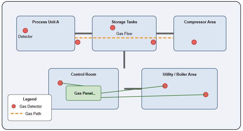
Layout of gas detection systems in an industrial complex

Vision and Optical Sensors

For inspection, identification, and quality control, modern industrial automation is progressively employing vision and optical sensors.

Industrial cameras, laser sensors, and color sensors all fall under these. They allow dimensional measurement, barcode reading, and defect detection, among other operations. 

High-speed analysis of goods using machine vision systems involves cameras, illumination, and picture processing programs.

Laser sensors provide exact distance and thickness readings even for little or fast-moving items.

Improved product quality and less waste in automated manufacturing lines depend mostly on optical sensors. 

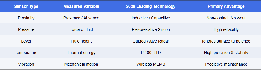
Sensor Comparison Table

This table sorts conventional industrial sensors by the measured variable, dominating technology, and primary advantage.

It underlines how every sensor type is designed for certain uses to increase dependability, accuracy, and predictive maintenance in industrial systems: non-contact detection, precise pressure measuring, steady temperature sensing, or vibration monitoring, for instance. 

Rise of IO-Link and Wireless Sensing  

The movement from basic analog signals (4-20mA) toward IO-Link communication is a major trend now.

This digital protocol lets sensors share diagnostic data internal temperature and operating hours in addition to a measurement. 

Moreover, wireless sensors have reduced the requirement for costly cabling in big projects. It enables the quick deployment of “smart nodes” in previously inaccessible locations.  

Conclusion 

The categorization of industrial sensors and their measurement techniques was discussed in this study.

Furthermore, the article details their real-world applications in several industrial contexts. Modern automation and control systems rely on industrial sensors. This lets machines and operations run safely, effectively, and intelligently. 

Sensors offer important information for decision-making and control. From gauging fundamental factors like pressure and temperature to facilitating sophisticated vision-based inspection. 

Sensor technologies keep developing in accuracy, lifetime, and communication features as data-driven industrial settings become more connected. Right sensor selection and use directly affect system performance, reliability, and operating expense.

FAQs

What are industrial sensors?

Devices that sense physical or chemical conditions like presence and temperature, and translate them into electrical signals for control or monitoring. It also deals with pressure. 

What major sensor types are there? 

Common examples include visual sensors and vibrations. It also includes flow, pressure, temperature, and proximity. 

How does a proximity sensor operate? 

Usually employing inductive or capacitive technology, detects object presence or lack without bodily contact. 

How in business do temperature sensors operate? 

They determine heat levels using thermocouples. RTDs and infrared sensors are also employed. 

Why should pressure sensors be utilized? 

 To keep an eye on the force applied by gases or liquids in systems such as pneumatics or hydraulics. 

For what purpose are flow sensors utilized? 

 They determine how fast liquids or gases flow through pipes. 

For what is a vibration sensor for? 

 Finds mechanical vibrations to help to maintain and monitor the condition. 

What are vision sensors?

 For inspection, barcode reading, and component guiding, they employ image processing and cameras. 

Why should one select non-contact sensors? 

 They help to cut down on wear and shield from interference from hostile surroundings. 

Can sensors measure multiple materials? 

 Yes, inductive sensors, for example, detect metals; capacitive sensors detect both metals and non- metals.


Indoor vs Outdoor Extension Cords: Key Differences You Need to Know

If you’ve ever grabbed the nearest extension cord without thinking twice, you’re not alone, but you could be putting your home, equipment, or even your life at risk.

The difference between indoor and outdoor extension cords goes far beyond the color of the jacket.

Understanding these differences is essential for safety, performance, and compliance with electrical codes.

cords soIn this guide, we’ll break down everything you need to know about indoor vs outdoor extension cords, so you always choose the right one for the job.

Why the Difference Between Indoor and Outdoor Extension Cords Matters

Extension cords are not a one-size-fits-all product. Using an indoor cord outside or even in a damp garage can lead to electrical shock, fire hazards, or damaged equipment.

Outdoor extension cords are engineered to handle environmental stressors that would quickly degrade an indoor cord.

Knowing which cord to use isn’t just a matter of convenience; it’s a matter of safety.

Insulation and Jacket Material

The most visible difference between indoor and outdoor extension cords is the outer jacket.

Indoor extension cords typically feature a lightweight, flexible PVC (polyvinyl chloride) jacket.

This is fine for dry, temperature-controlled environments, but it becomes brittle, cracks, or degrades when exposed to UV rays, moisture, extreme heat, or cold.

Outdoor extension cords use a much thicker, more durable jacket usually made from rubber, vinyl, or a thermoplastic elastomer (TPE) compound. These materials are:

  • Weather-resistant: They can handle rain, humidity, and temperature swings without cracking.
  • UV-resistant: Prolonged sun exposure won’t degrade the jacket.
  • Flexible in cold temperatures: Outdoor cords remain pliable even in freezing conditions, unlike indoor cords that stiffen and become difficult to coil.

Wire Gauge (AWG Rating)

The American Wire Gauge (AWG) number tells you how thick the conductors inside the cord are.

Counterintuitively, a lower AWG number means a thicker wire, and a thicker wire can handle more current with less voltage drop.

  • Indoor cords are often 16 AWG or 18 AWG, suitable for lamps, phone chargers, and light-duty electronics.
  • Outdoor cords typically range from 10 AWG to 14 AWG, designed to power tools, lawn equipment, air compressors, and other high-draw devices.

Using an undersized wire gauge outdoors, especially over long distances, causes the cord to overheat, which can melt insulation, trip breakers, or start a fire.

Quick rule: The longer the cord runs and the higher the wattage of your device, the lower the AWG number you need.

NEMA Plug and Connector Ratings

Outdoor extension cords feature NEMA 5-15 or higher-rated connectors with additional features:

  • Grounded plugs (3-prong): Always required outdoors for shock protection.
  • Weatherproof or locking connectors: Many outdoor cords include molded or sealed ends that resist moisture ingress.
  • Blade covers or shutters: Some outdoor cords include covers that protect the plug face when not in use.

Indoor cords often use lighter-duty connectors and may not be grounded, which is a serious hazard in any wet or outdoor setting.

Safety Certifications and Markings: What the Letters Mean

One of the easiest ways to distinguish indoor from outdoor extension cords is to read the markings printed on the jacket. These letters tell you exactly what a cord is rated for.

LetterMeaning
WRated for outdoor (Weather-resistant) use
SService grade (general use)
JJunior service (lighter duty, 300V)
TThermoplastic jacket
PParallel construction (lamp/household cord)
EThermoplastic elastomer jacket
OOil-resistant jacket

Outdoor cords will have a “W” in their designation, for example, SJTW or SOOW. If you don’t see a “W,” the cord is not rated for outdoor use.

Always look for cords listed by UL (Underwriters Laboratories), ETL, or another NRTL (Nationally Recognized Testing Laboratory). This confirms the cord has been independently tested to meet safety standards.

Amperage and Wattage Capacity

Outdoor tools and equipment typically draw significantly more power than household electronics. Here’s a general capacity guide:

Gauge (AWG)Max AmperageTypical Use
18 AWG10ALamps, phone chargers
16 AWG13AFans, small appliances
14 AWG15APower tools, space heaters
12 AWG20AAir compressors, large tools
10 AWG25ARVs, heavy equipment

Outdoor extension cords should always be matched to the amperage rating of the equipment you’re powering. Overloading a cord even momentarily generates heat that can cause the insulation to fail.

Length and Voltage Drop

Outdoor projects often require running extension cords over longer distances across a yard, up a ladder, or around a worksite.

The longer the cord, the greater the voltage drop, which reduces the power reaching your tool and can cause motors to overheat or run inefficiently.

To compensate for longer runs:

  • Use a lower AWG cord (thicker wire) for runs over 50 feet.
  • For runs over 100 feet, go to 12 AWG or even 10 AWG.
  • Avoid daisy-chaining multiple extension cords together, as this multiplies voltage drop and creates overheating risks.

Indoor cords are rarely used over distances where this becomes a concern, which is part of why they’re built with thinner, higher AWG wire.

Temperature and Environmental Ratings

Outdoor extension cords are rated to perform across a broad temperature range, typically from -40°F to 140°F (-40°C to 60°C). This makes them suitable for winter work, summer sun, and everything in between.

Indoor cords have no meaningful temperature rating because they’re assumed to operate in climate-controlled spaces.

Exposing them to freezing temperatures causes the jacket to crack; exposing them to direct sunlight accelerates UV degradation, making the insulation brittle and unsafe.

Get Your Extension Cord Here.

Can You Use an Outdoor Extension Cord Indoors?

Yes, and it’s often the safer choice. An outdoor-rated cord used indoors is perfectly safe.

The extra durability, thicker insulation, and grounded plug simply give you more protection.

The only downside is that outdoor cords are heavier and less flexible, which can be mildly inconvenient for light-duty indoor tasks.

The reverse, however, is never acceptable. An indoor cord used outdoors, even temporarily, is a genuine safety risk. It is not weather-resistant, may not be grounded, and is likely underrated for the load.

GFCI Protection for Outdoor Use

Whenever you use an extension cord outdoors, the outlet you plug into should be a GFCI (Ground Fault Circuit Interrupter) outlet.

GFCI outlets shut off power within milliseconds if they detect a ground fault, like a cord lying in a puddle.

The NEC (National Electrical Code) requires GFCI protection for all outdoor outlets, garages, bathrooms, and kitchens.

Some outdoor extension cords come with a built-in GFCI module on the cord itself, which is an excellent safety feature for worksites or locations where you can’t guarantee the outlet is GFCI-protected.

Quick Reference: Indoor vs Outdoor Extension Cord Comparison

FeatureIndoor CordOutdoor Cord
Jacket materialLight PVCRubber / TPE / Heavy vinyl
UV resistanceNoYes
Weather resistanceNoYes
Typical AWG16–18 AWG10–14 AWG
Grounded (3-prong)SometimesAlways
“W” rating on jacketNoYes
Temperature rangeNarrow (indoor only)Wide (-40°F to 140°F)
Safe to use outdoors?NoYes
Safe to use indoors?YesYes

Common Mistakes to Avoid

  • Running an indoor cord under a rug or carpet: This traps heat and is a fire hazard — indoors or outdoors.
  • Using a cord that’s too long or too thin: Always match gauge to distance and load.
  • Leaving cords coiled while in use: A tightly coiled extension cord under load builds heat in the center. Unroll it fully before use.
  • Ignoring the “W” marking: This is the single clearest indicator that a cord is outdoor-rated. Don’t skip it.
  • Daisy-chaining cords: Each additional cord adds resistance, voltage drop, and heat buildup.

Final Thoughts

The difference between indoor and outdoor extension cords isn’t just technical; it’s a matter of safety.

Outdoor extension cords are built tougher, rated for weather, and designed to carry heavier loads over longer distances.

Indoor cords are lighter, cheaper, and perfectly suited for dry, controlled environments, but they have no place in your backyard, garage, or jobsite.

When in doubt, read the jacket markings, match the AWG to your load and distance, look for the “W” rating, and always plug into a GFCI outlet outdoors. A few seconds of checking the label can prevent a dangerous situation.

For more wiring guides, electrical safety tips, and control circuitry breakdowns, explore the rest of ControlCircuitry.com.

How to Convert F to C

If you’ve ever looked at an American weather forecast showing 95°F and had absolutely no idea whether to grab a sweater or sunscreen, you’re in the right place.

The world uses two main temperature scales: Fahrenheit (used mainly in the United States) and Celsius (used almost everywhere else). Knowing how to convert between them is a surprisingly useful skill.

Don’t worry, you don’t need to be a math wizard. By the end of this article, you’ll be converting temperatures in your head.

The Main Formula
°C = (°F − 32) × 5/9
Subtract 32, then multiply by five-ninths. That’s literally all there is to it.

Why Do Two Temperature Scales Even Exist?

Fahrenheit was invented in 1724 by a German physicist named Daniel Gabriel Fahrenheit. He based the scale on a mix of reference points, including the temperature of an ice-salt mixture and human body temperature. It caught on in English-speaking countries, and the United States still uses it today.

Celsius (also called “Centigrade”) was developed by Swedish astronomer Anders Celsius in 1742.

His system is a much simpler conceptually: 0°C is where water freezes, and 100°C is where water boils.

Because of that clean logic, most of the world — and all of science — adopted Celsius.

???? Quick Context

Only three countries officially use Fahrenheit as their everyday temperature scale: the United States, the Cayman Islands, and Liberia. The rest of the world runs on Celsius.

The Formula: How to Convert F to C

Here is the official formula to convert Fahrenheit to Celsius:

°C = (°F − 32) × 5 ÷ 9

Let’s break that down into plain English:

Let’s break that down into plain English:

1: Take your Fahrenheit temperature. Start with whatever temperature you have in °F.

2: Subtract 32. This “resets” the scale so that both systems start at the same reference point, the freezing point of water.

3: Multiply by 5, then divide by 9 (or just multiply by 0.5556 if that’s easier.) This scales the number to match the Celsius degree size.

✅ Tip

Multiplying by 5/9 is the same as multiplying by 0.5556. If you’re using a calculator, that might be faster.

Worked Examples Step by Step

Example 1: Boiling Water (212°F)

Example Calculation
Start 212°F
Step 1 212 − 32 = 180
Step 2 180 × 5 = 900
Step 3 900 ÷ 9 = 100
= 100°C ✓

Perfect, water boils at 100°C. The formula checks out.

Example 2: A Hot Summer Day (98°F)

Example Calculation
Start 98°F
Step 1 98 − 32 = 66
Step 2 66 × 5 = 330
Step 3 330 ÷ 9 = 36.67
≈ 36.7°C

That’s a very hot day, basically at body temperature. Makes sense.

Example 3: Freezing Point (32°F)

Example Calculation
Start 32°F
Step 1 32 − 32 = 0
Step 2 0 × 5 = 0
Step 3 0 ÷ 9 = 0
= 0°C ✓

Water freezes at 0°C, exactly as expected.

Quick Reference Temperature Chart

Sometimes you just need a fast lookup. Here are the most common everyday temperatures converted from Fahrenheit to Celsius.

Fahrenheit (°F) Celsius (°C) What It Feels Like
−40°F−40°CExtreme cold (these two scales are equal here!)
14°F−10°CVery cold winter
32°F0°CFreezing point of water
50°F10°CCool wear a jacket
59°F15°CMild spring morning
68°F20°CComfortable room temperature
77°F25°CWarm and pleasant
86°F30°CHot summer day
95°F35°CVery hot stay hydrated
104°F40°CDangerously hot
212°F100°CBoiling point of water

The Quick Mental Math Trick

Don’t have a calculator? Here’s a rough shortcut you can use in your head to get a close estimate, not exact, but good enough for everyday. use:

°C ≈ (°F − 30) ÷ 2

This isn’t perfectly accurate, but it’s much easier to do mentally, and it’ll get you in the right ballpark. Let’s test it on 68°F.

(68 − 30) ÷ 2 = 38 ÷ 2 = 19°C  (actual answer: 20°C)

Close enough to know it’s a pleasant day. Use the mental trick for a quick gut check and the real formula when precision matters.

⚠️ Heads Up

The shortcut works best in the 50–100°F range. At very low or very high temperatures, the estimate drifts further from the true value. Use the proper formula for accuracy.

When Does This Actually Come Up in Real Life?

Knowing how to convert F to C is more useful than you might think. Here are situations where you’ll actually reach for this formula.

✈️
Traveling Abroad

Most countries use Celsius in weather forecasts. You’ll want to know if 22°C means a light jacket or a beach day.

????
Cooking & Baking

US recipes often list oven temperatures in °F. If your oven uses °C, you’ll need this conversion every time.

????
Science & Engineering

All scientific measurements use Celsius (and Kelvin). If you work with data or sensors, conversions are routine.

????️
Health & Medicine

Body temperature, fever thresholds, and medical data use Celsius in most parts of the world.

????
Gardening

Seed packets and gardening guides from different countries use different scales for soil and air temperatures.

????
Electronics & Hardware

CPU temperatures, component specs, and thermal limits are nearly always listed in Celsius.

Going the Other Way: Celsius to Fahrenheit

If you ever need to convert in the other direction from Celsius back to Fahrenheit, the formula is simply reversed.

°F = (°C × 9/5) + 32

Multiply your Celsius value by 9, divide by 5, then add 32. For example, 25°C converts to:

(25 × 9) ÷ 5 + 32 = 225 ÷ 5 + 32 = 45 + 32 = 77°F


Frequently Asked Questions

What is 100°F in Celsius?

Using the formula (100 − 32) × 5/9 = 68 × 0.5556 ≈ 37.8°C. That’s just slightly above normal human body temperature (37°C), which is why a 100°F fever indicates you’re running hot.

At what temperature are Fahrenheit and Celsius the same?

They meet at exactly −40°. At −40°F and −40°C, both scales read the same number. It’s a well-known quirk of the two systems.

Is there an easy way to remember the formula?

Yes, remember this phrase: “Minus 32, times five, divide by nine.” Say it a few times, and it’ll stick. Alternatively, bookmark this page for quick reference.

What is the room temperature in Celsius?

Standard room temperature is typically considered 68–72°F, which equals about 20–22°C. Most comfort guidelines and product specs reference 20°C as a baseline.

Is 37°C a normal body temperature?

Yes, 37°C (98.6°F) is the classic “normal” human body temperature, though research shows that healthy individuals can range from about 36.1°C to 37.2°C (97°F to 99°F).

Wrapping It Up

Converting Fahrenheit to Celsius doesn’t have to be intimidating. The formula (°F − 32) × 5/9 is all you ever need. Subtract 32, then multiply by five-ninths. That’s it.

For quick mental estimates, use the shortcut (°F − 30) ÷ 2; it’s fast and close enough for everyday situations.

And when you need precision, like in science, cooking, or engineering, stick to the real formula.

Now that you know how to convert F to C, you’ll never be lost looking at a foreign weather forecast or an international recipe again.

Save this page for future reference, or share it with a friend who still thinks 100°F is a mystery.

Types of Pressure Switches

Industrial, business, and residential systems often employ pressure switches as their primary control elements.

Their primary purpose is to monitor pressure. They cause an electric response once a preset value is reached.

Pressure switches operate discretely, unlike pressure sensors or transmitters, which provide continuous measurement.

They only switch a circuit ON or OFF. This basic habit makes them both extremely dependable and cheap.

Pressure switches are regularly employed in pumps as well as in compressors. In addition, they are certainly useful in boilers, hydraulic systems, and safety interlocks.

Knowledge of the many kinds of pressure switches and how they operate assists engineers and technicians.

Especially in choosing the appropriate equipment for performance, safety, and longevity in demanding situations.

This paper discusses the primary kinds of pressure switches. It also explains their operational mechanisms and typical uses.

What is a pressure switch?

An electromechanical or electronic device called a pressure switch answers fluid pressure variations. The switch activates internal contacts once the pressure hits a specific threshold.
These connections may either open or close an electrical circuit. The regulated circuit can begin or halt equipment.

It can activate alarms. It can also guard systems from excessive or under-pressure conditions.

Basic block diagram of a pressure switch indicating pressure inlet, sensor element, mechanical linkage, and electrical contacts

Fundamental Working Mechanism of Pressure Switches

Force balance underlies all pressure switch systems. Mechanical force results from pressure exerted on a sensor element. This power is contrasted with a reference or preloaded spring.
The switch switches state when the pressure force surpasses or falls below the established threshold. 

Mechanical pressure switches directly use this action to engage electrical contacts. The pressure in electronic pressure switches is first transformed into an electrical signal. It is subsequently processed by circuits to power a solid-state or relay output.

Mechanical Pressure Switches

The most conventional and often used type of mechanical pressure switch is one. Mechanical movement and electrical contacts are all they depend on.

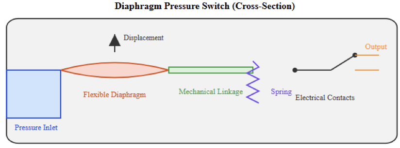
Diaphragm

The diaphragm is the core mechanical element. It is part of a pressure transmitter. It is designed to flex under pressure. This diversion activates a linkage attached to a snap-action contact or microswitch.

Typically constructed of metal or elastomer, the diaphragm varies depending on the fluid and pressure range.

Commonly used in air, gas, and water systems, low to medium pressures make these switches fit.

Cross-sectional diaphragm pressure switch diagram with diaphragm displacement and contact actuation 

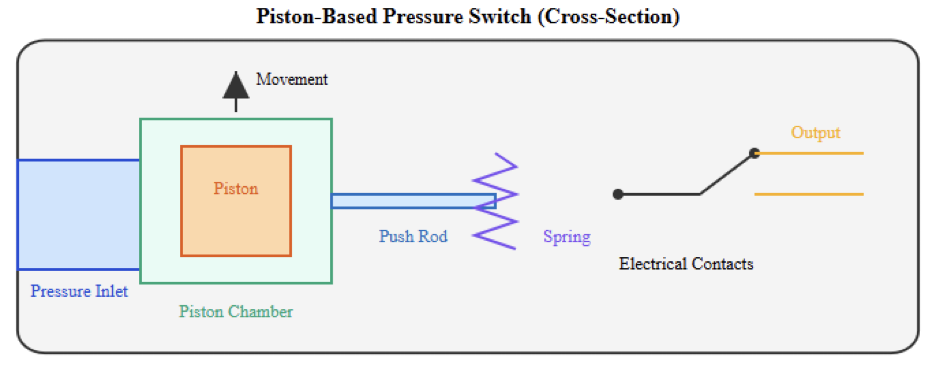
Piston 

Pressure in piston pressure switches presses a small piston rather than a diaphragm. The piston travels linearly against a spring. The pistons activate the electrical contacts when the force balance shifts.

High-pressure applications benefit from sturdy piston switches. Common applications for them are hydraulic systems. Pressures there are much greater than in pneumatic systems.

Piston-based pressure switch highlighting spring mechanism and piston movement

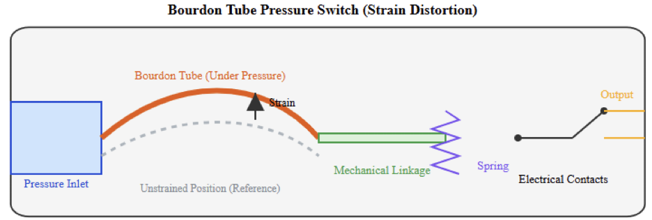
Bourdon Tube 

Bourdon tubes are the pressure-sensing components in this design. Pressure straightens when it enters the curved tube. Links transfer the mechanical motion to trigger the contact switches.

Usually found in high-pressure steam or gas situations, Bourdon tube pressure switches are robust.

They can tolerate severe conditions. Their reaction time is usually slower than that of diaphragm-based designs.

Bourdon tube pressure switch shows the tube under strain distortion

Switches with differential pressure

Differential pressure switches actually detect the difference. This difference is between two pressure points rather than absolute pressure. Two pressure ports joined to opposite sides of a piston or diaphragm are employed here.

The switch triggers when the pressure differential goes beyond the set point. Filter monitoring, flow verification, and ventilation systems usually make use of these switches.

A blocked filter, for instance, raises differential pressure across it. This state is discovered by the pressure switch. It then activates an alarm or maintenance indicator.

Vacuum Pressure Switches

At pressures less than those of the atmosphere, vacuum pressure switches work. Though their calibration range is calibrated for vacuum circumstances, their operating principle is comparable to that of standard pressure switches.

Packaging machines, medical devices, and vacuum pumps all include these switches extensively. Before a process starts, they help to guarantee enough suction.

Electronic Pressures Switches

Sensors and electronic circuits in electronic pressure switches take the place of mechanical links. Pressure is transformed into an electrical signal by a pressure sensor.

A piezoresistive or capacitive element is commonly used. A comparator or microcontroller handles this signal.

The output changes state when the measured pressure passes the configured threshold. The output could be a transistor signal, a solid-state relay, or an electromechanical relay.

Higher precision, better repeatability, and digital configurability are offered by electronic pressure switches.

Solid-State Pressure Switches

Without moving components, solid-state pressure switches are a sort of electronic switch. Semiconductor sensors and electronic outputs make up the whole.


These switches provide a long service life and a high switching frequency since there are no mechanical contacts.

They are perfect for applications requiring dependable, quick reactions. Although they typically need an external power supply. They could also be more prone to electrical noise.

Fixed vs Adjustable Pressure Switches

Pressure switches can be factory-set or configurable. Adjustable switches let the consumer use a screw or digital interface to alter the setpoint. During commissioning or system adjustment, this freedom comes in handy.

Fixed pressure switches have manufacturer-defined switching points. Usually employed in safety-critical situations. Tampering has to be avoided.

Normal Open and Normal Closed Contacts

Normal open (NO), normally closed (NC), or changeover (SPDT) contacts are possible on pressure switches. The decision is influenced by safety requirements and system logic.

Normally, closed contacts are frequently utilized in safety systems, for instance. A power failure or a damaged wire activates a fault state.

Applications for Pressure Switches

Widely used in systems requiring pressure monitoring to guarantee dependable and safe operation are pressure switches. Often used to provide safety interlocks under unusual pressure circumstances. 

They automate machinery and guard equipment from damage. Because of their straightforward structure and reliable switching performance, pressure switches fit several sectors.

They serve both protection and control applications. They are found in many different industrial and commercial sectors.

  • Manage water pumps’ automatic beginning and stopping depending on system pressure.
  • Overpressure damage in air and gas compressors should be avoided.
  • Serve as safety interlocks in steam systems and boilers.
  • Check HVAC system airflow and filter integrity
  • Because of their straightforward construction, they offer dependable operation for both control and protection systems.

Conclusion

This article examined the fundamental forms of pressure switches in contemporary systems. It also reviewed their functioning mechanisms.

Monitoring and regulation of pressure in many different uses depend critically on pressure switches.

Each kind works on the same basic principle of pressure-induced force, resulting in an electrical action.

This applies from basic diaphragm switches to complex electronic and solid-state designs.

Pressure range, fluid type, precision, response time, and ambient circumstances will all influence the choice of a pressure switch. Knowing how every kind of function helps engineers and technicians. 

It enables them to create more dependable, more effective, and safer systems. Though digital sensing has improved, pressure switches are still vital elements in contemporary industrial control and automation.

FAQs: Types of Pressure Switches

A pressure switch is what? 

Once the preset pressure level is met, the switch changes the circuit state. 

Which pressure switch varieties predominate? 

The common ones are mechanical pressure switches. Also, there is the existence of electronic (solid-state) pressure switches. 

Mechanical pressure switches employ what kind of sensing elements? 

Common sensing elements include diaphragms and pistons. Without forgetting the Bourdon tubes. 

What is a diaphragm pressure switch? 

It activates contacts using a flexible diaphragm acting under pressure. 

What is the purpose of a piston pressure switch?

Piston pressure switches are generally used in high-pressure hydraulic situations.

Bourdon tube pressure switch definition? 

It employs a bent tube that straightens under pressure to set off switching. 

 A differential pressure switch is which? 

It runs on the pressure difference between two pressure locations.

Pressure Transmitter Working Principle

In industrial systems, pressure measurement is a fundamental necessity. Many procedures rely on precise pressure data.

These procedures have to run efficiently and securely. Pressure transmitters offer this data. 

They translate physical pressure into an electrical signal. Control systems are able to interpret this indication.

Oil and gas, among other industries, make use of these technologies. Additionally utilized in power generation and water treatment. 

They are also essential for manufacturing, and automation absolutely depends on their dependability.

Process control also depends on them greatly. Knowing how a pressure sensor functions helps engineers. It assists them in choosing the ideal gadget. 

It also helps to identify flaws. It encourages better system design. The functioning theory of pressure transmitters is discussed in this article.

Moreover, it covers their essential parts. Technologies of sensing are reviewed. Common industrial uses are shown. 

What is a pressure transmitter? 

A pressure transmitter is an industrial instrument, and it is used to gauge the pressure of fluids or gases.

It senses pressure from a process and changes it to an electrical output signal. The signal then goes to the controllers. 

Indicator targets can also get it. Monitoring devices can get it as well. Normally, the output is standardized.

This makes it possible to seamlessly connect with control systems. Typical outputs come in the shape of modern signals. 

Voltage signals are utilized as well. Digital communication protocols are common. Transmitters offer continual measurement, unlike basic pressure gauges. They fit remote monitoring. Moreover, they support automation. 

Basic Theory of Pressure Measurement 

Pressure is defined as a force applied over a surface area. This force is supplied by liquids in industrial systems.

Pipes, tanks, or containers hold these fluids. Their movement results from pressure applied to a transmitter surface. 

Mechanical and very little, this movement is It is also remarkably exact. The transmitter is intended for this detection. It turns the motion into an electric signal.

The signal has to be measurable. The accuracy of this conversion is important. It affects the accuracy of the pressure measurement. 

Pressure Transmitter: Main Components

A pressure transmitter consists of several key components. These components work together. The pressure port allows the process fluid to enter.

The fluid enters the transmitter through this port. This port directs pressure toward a sensing element. 

The sensing element is usually a thin diaphragm. It reacts to applied pressure. As pressure changes, the diaphragm deflects slightly.

Attached to the diaphragm is a sensor element. This sensor converts mechanical deformation. 

The deformation becomes an electrical change. The electrical signal produced is very small. It is also unstable. Signal conditioning electronics amplify the signal. They also stabilize it.

The final stage converts the signal. It becomes a standardized output. This output is suitable for transmission. It is sent to control systems.

Block diagram showing pressure port, diaphragm, sensor, signal conditioning, and output stage

 Diaphragm Operation

The diaphragm is the core mechanical element. It is part of a pressure transmitter. It is designed to flex under pressure.