What is a soft starter, and when should it be used instead of a VFD?

Electric motors drive most industrial processes across modern facilities worldwide. They can support production, transport, pumping, and ventilation systems.

Their starting behavior significantly influences electrical stability and mechanical reliability throughout the installation. 

Engineers must carefully choose appropriate motor starting methods to prevent unnecessary stress and operational disruptions.

Incorrect selection may cause voltage drops, excessive torque shocks, or premature equipment wear. 

Two widely applied solutions are soft starters and variable frequency drives in modern industry.

Although both technologies manage motor startup, their objectives and capabilities differ substantially. 

Many professionals assume a variable frequency drive always represents the superior technical solution.

However, this assumption often leads to unnecessary complexity and increased project cost. 

A clear understanding of operational requirements ensures rational and economical equipment selection.

This article highlights the operating principles and practical criteria for selecting soft starters instead of variable-frequency drives.

What is a soft starter?

A soft starter is an electronic device designed specifically to control motor acceleration during startup.

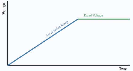
It gradually increases the voltage applied to the motor terminals using controlled semiconductor switching devices. 

By reducing the initial applied voltage, the motor draws lower inrush current from the electrical network.

This controlled current ramp significantly minimizes voltage dips affecting other connected equipment. 

Reduced electrical stress improves the stability of transformers, generators, and upstream distribution components.

Soft starters commonly employ silicon-controlled rectifiers arranged in antiparallel configurations for each phase.

By adjusting the firing angle of these devices, the effective RMS voltage increases smoothly.

Once the motor reaches near rated speed, an internal bypass contactor typically engages. 

This bypass action reduces thermal losses and improves the long-term efficiency of the equipment.

Importantly, a soft starter does not modify frequency during steady-state motor operation. 

After startup completion, the motor operates directly at line frequency and rated speed. The primary objective remains limiting mechanical shock and electrical stress during acceleration and stopping.

Mechanical systems particularly benefit from the smooth torque buildup provided by soft starters.

Gearboxes and couplings experience significantly lower dynamic stress during motor engagement. This situation is also common in belts and shafts. 

Gradual acceleration in pumping systems lowers hydraulic transients and lessens water-hammer effects. Installation complexity is still quite low relative to more sophisticated drive systems. 

 Usually, ramp time, initial voltage, and protection thresholds are set in parameter settings. For fixed-speed processes, this level of control often proves entirely sufficient.

What is a soft starter, and when should it be used instead of a VFD?

How a Variable Frequency Drive Operates

A variable frequency drive, often abbreviated as VFD, provides comprehensive control of motor speed and torque. Internally, it first rectifies incoming alternating current into a direct current link stage. 

An inverter section then reconstructs alternating current at a variable frequency and voltage.

Because motor speed is proportional to supply frequency, changing frequency enables precise speed regulation. 

Voltage modulation occurs simultaneously to maintain appropriate magnetic flux within the motor.

This coordinated control allows smooth acceleration. It also permits effortless deceleration and continuous speed adjustment.

VFDs continuously manage motor performance during the entire operation. This is not the case when soft taters are used.

They can implement programmable acceleration ramps, braking profiles, and torque limits. 

Many modern drives incorporate communication interfaces for integration with industrial automation networks.

Advanced features may include internal PID controllers, diagnostics, and energy monitoring capabilities. 

However, the switching nature of inverters introduces harmonic distortion into the electrical system.

Additional filtering or line reactors may therefore be required for compliance with standards. 

Installation typically demands careful attention to proper grounding considerations. This also applies to appropriate shielding and cable length. Initial investment cost is usually higher compared with soft starter solutions.


Basic Functional Blocks of a Variable Frequency Drive

Fundamental Differences Between the Two Technologies

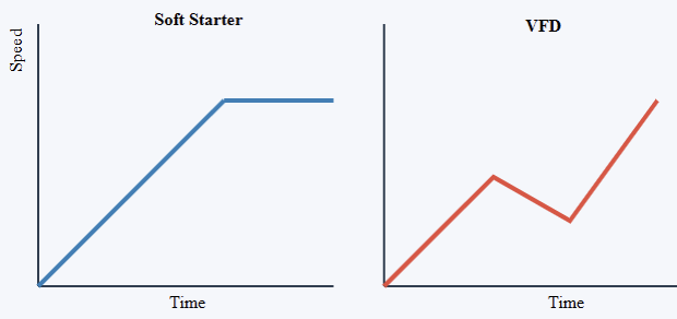
The essential distinction between a soft starter and a VFD lies in speed control capability. A soft starter only manages voltage during startup and stopping sequences. A VFD continuously regulates frequency and voltage during steady-state operation.

Consequently, soft starters do not provide energy savings in constant torque processes. In contrast, VFDs can significantly reduce energy consumption in variable torque loads such as pumps and fans.

From a system perspective, soft starters generate minimal harmonic distortion during operation.

VFD installations may require harmonic studies and mitigation measures in sensitive networks. 

Commissioning complexity also differs considerably between the two solutions. Soft starters generally require fewer parameters and shorter setup procedures.

VFDs demand more detailed configuration, especially when advanced control features are utilized. 

Maintenance skill requirements often increase with drive complexity. Therefore, technology selection must align carefully with actual process needs. It should not be based solely on perceived sophistication.

Soft Starter vs VFD: Operational Control Comparison

When to Use a Soft Starter Instead of a VFD

Soft starters are particularly appropriate for applications operating at constant rated speed. Conveyors transporting materials at fixed throughput represent a common example. 

Centrifugal pumps running continuously at nominal flow without modulation also qualify. Large fans designed for steady ventilation loads similarly benefit from soft-starting methods. In these situations, speed variation does not provide meaningful process advantages.

High inertia loads often require controlled acceleration to prevent mechanical damage. Soft starters limit torque shocks and reduce stress on couplings and transmission components. 

Electrical systems supplied by generators or weak grids benefit from reduced starting current.

Lower inrush current prevents excessive voltage drops affecting other critical loads. Water distribution systems experience fewer hydraulic transients when pumps start gradually. 

Budget-constrained projects frequently favor soft starters due to lower capital cost. Facilities with limited technical support also appreciate their simpler architecture.

When operational flexibility is unnecessary, adding a VFD introduces avoidable complexity.

Situations Where a VFD Is More Suitable

Despite their advantages, soft starters cannot replace VFDs in dynamic process environments.

Applications requiring variable flow control depend on continuous speed adjustment capabilities.

HVAC systems achieve significant energy savings by modulating pump speeds. This also applies to fan speed. 

Conveyor lines with changing production rates require flexible speed control. Processes demanding precise torque regulation at low speeds necessitate inverter technology. Regenerative braking or advanced motion control functions further justify VFD implementation.

In these contexts, the higher investment cost becomes economically defensible. Improvements in energy efficiency and better process control balance initial expenditures over time. 

Advanced monitoring and predictive maintenance techniques also depend on integration with automation systems. Engineers, therefore, have to assess lifecycle advantages rather than just the buy price.

Practical Engineering Considerations 

Correct equipment selection requires thorough analysis of load characteristics and operational objectives.

Motor insulation class and compatibility must be verified, particularly for inverter applications.

Cable lengths and electromagnetic compatibility considerations become critical in VFD installations.

Protection coordination must match the fault levels present in the distribution system. Environmental conditions such as dust and humidity influence enclosure selection. Also, ambient temperature impacts the aforementioned selection.

Correct equipment selection requires thorough analysis of load characteristics and operational objectives. Motor insulation class and compatibility must be verified, particularly for inverter applications. 

Cable lengths and electromagnetic compatibility considerations become critical in VFD installations.

Protection coordination should align with available fault levels within the distribution system.

Environmental conditions such as dust, humidity, and ambient temperature influence enclosure selection. 

Proper commissioning procedures ensure ramp times and protection parameters match application requirements. Oversizing equipment unnecessarily increases capital cost without technical benefit. 

Under-sizing introduces overheating risks and potential operational instability. A balanced engineering approach evaluates performance, reliability, and economic constraints simultaneously.

Conclusion

This article introduced the functional distinctions and selection criteria for soft starters and variable frequency drives in industrial systems.

Soft starters provide controlled acceleration that reduces electrical and mechanical stress during motor startup. 

They offer cost-effective solutions for constant speed applications without sacrificing reliability.

Variable frequency drives deliver continuous speed control, advanced functionality, and potential energy savings. 

Their flexibility makes them indispensable in processes requiring dynamic adjustment and optimization.

Choosing between the two technologies depends on load behavior and performance objectives. Also, it relies on the infrastructure limitations of a certain project. 

Avoiding unnecessary complexity improves long-term reliability and reduces lifecycle cost. Careful engineering evaluation ensures that each motor application receives the most appropriate and efficient solution.

FAQs: What is a soft starter?

Describe a soft starter

 By slowly raising the voltage during starting, a soft starter is a device lowering motor inrush current. 

Soft starters diverge from VFDs in their operational characteristics 

 While a VFD controls frequency and voltage for whole speed control, a soft starter only controls start-up voltage. 

 When should you install a soft starter? 

 Use a soft starter for applications with a fixed speed wherein smooth starts and lower electrical stress are most important. 

When should a VFD be preferred? 

 When variable speed control, energy savings, or sophisticated motor control is needed, pick a VFD. 

 Do soft starters use power during operation? 

 No, soft starters cut current only at startup and do not provide continuous energy savings like VFDs. 

 Are VFDs more expensive and less complicated than soft starters? 

 Yes, VFDs often have less intricacy and lower initial cost than soft starters.

PLC Troubleshooting Methodology Step by Step

Programmable logic controllers represent a vital part of the automation setup not only in industries but also worldwide.

They work together with machines, process flows, and safety features in a variety of sectors. 

When PLC systems fail, production losses and safety risks quickly increase significantly. Therefore, a structured troubleshooting methodology becomes critical for reliable operations. Random guessing wastes time and may introduce additional faults.

In troubleshooting, engineers’ diagnostic approaches need to be disciplined, repeatable, and technically sound.

Successful troubleshooting is a mixture of electrical knowledge, process understanding, and logical reasoning skills. 

On top of that, it requires maintaining accurate records and following the steps of verification in a systematic way each time.

It also demands careful documentation and systematic verification steps consistently. A clear methodology reduces downtime and improves maintenance efficiency considerably. 

PLC Troubleshooting Methodology Step by Step

Technicians gain confidence when following organized diagnostic procedures daily. This article explains step-by-step PLC troubleshooting methodology principles.

Step 1: Understanding the Problem Clearly

The first step involves clearly defining the observed problem precisely. Symptoms must be described accurately without assumptions or speculation. Operators should explain what the machine is doing incorrectly now. 

Service logs often highlight recurring faults or hidden trends. Always determine whether the issue is electrical, logical, or mechanical. A machine not starting differs from incorrect sequence execution behavior. 

Clarifying scope prevents unnecessary modifications to unrelated control sections. Good troubleshooting begins with careful listening and direct observation. Accurate problem statements guide the entire diagnostic process effectively.

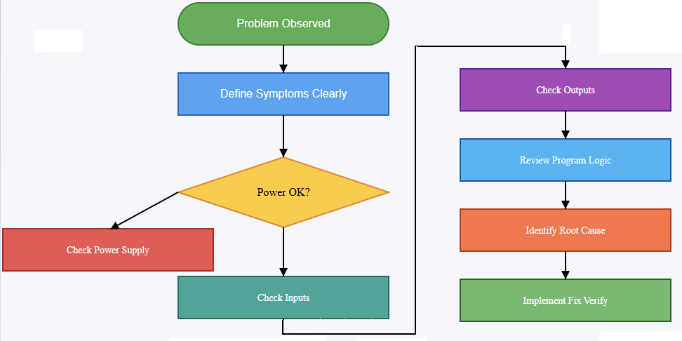
The following diagram visually represents the logical decision-making path used during PLC troubleshooting.

It emphasizes sequential validation of power, hardware, and software before implementing corrective actions. 

The flowchart reinforces disciplined thinking and reduces the likelihood of unnecessary component replacement or incorrect program modifications

Flowchart of PLC Troubleshooting (step by step) 

Step 2: Our Safety and Proper Preparation

Be sure to fully and strictly comply with all safety measures, first of all, if you are going to do diagnostic work.

Lockout and tagout are the ways used to protect workers from the hazard of getting an unexpected energization. Personal protective equipment must match the system voltage levels present.

Never bypass safety circuits without authorized risk assessment documentation. Review electrical drawings and control schematics thoroughly beforehand. Confirm the correct PLC model and firmware version identification clearly. 

Verify available programming software matches the controller requirements exactly. Preparation minimizes risk and prevents avoidable configuration errors later. Organized preparation establishes professional discipline in maintenance activities.

Step 3: Verifying Power Supply and Hardware Status

Many PLC issues originate from simple power problems frequently. Check the incoming supply voltage using calibrated measurement instruments properly. Confirm correct voltage levels at PLC power terminals directly. 

Inspect power supply modules for overheating or visible damage signs. Observe status LEDs indicating healthy or fault conditions carefully. A flashing error LED often signals configuration or hardware issues. 

Loose terminal connections frequently cause intermittent system behavior problems. Grounding integrity should also be verified carefully and methodically.

Stable power conditions form the foundation for reliable operation. Hardware verification eliminates many common faults early and quickly.

Step 4: Checking Input Devices and Field Signals

After confirming power integrity, examine input devices systematically. Verify sensors receive proper operating voltage from control panels consistently. Use multimeters to measure actual input signal states accurately.

Observe PLC input indicator LEDs for state changes visually. If an input never activates, inspect wiring continuity carefully. Broken conductors commonly occur near moving mechanical assemblies. 

Confirm the correct sensor type and wiring configuration carefully. Compare field wiring with electrical schematics meticulously and patiently.

Incorrectly wired inputs often mimic complex logical faults misleadingly. Reliable inputs are essential for correct control decisions.

The next diagram illustrates the complete signal path from a field sensor to the final actuator. It helps engineers and technicians understand different important points. These include where to measure voltage, observe LED indicators, and isolate faults. 

By visually separating field devices, wiring, and PLC modules, the diagram clarifies how input problems differ from output or logic-related issues.

Step 5: Evaluating Output Devices and Actuators

Outputs must be tested methodically after validating inputs completely. Check output indicator LEDs within the PLC module first. If the LED activates but the device remains off, suspect wiring issues. 

Measure output voltage at terminal blocks carefully using instruments. Inspect contactors, relays, and solenoids for mechanical sticking conditions. Overloaded outputs may trigger protection circuits internally sometimes. 

Confirm output type matches device electrical characteristics exactly. Never connect inductive loads without proper suppression components installed.

Hardware validation eliminates confusion before software analysis begins logically. Functional outputs confirm that commands reach physical equipment reliably.

Step 6: Reviewing PLC Program Logic Step by Step

Once hardware integrity is confirmed, analyze program logic carefully. Open the ladder diagram or relevant programming language environment. Follow signal flow from inputs toward final outputs sequentially. 

Use online monitoring tools to observe rung execution status. Identify whether conditions evaluate as true or false unexpectedly.

Force inputs cautiously only when safe and authorized officially. Examine timers and counters for unexpected accumulated values carefully. 

Incorrect preset values frequently cause sequence delays unexpectedly. Look for overwritten variables or duplicate memory addresses systematically.

Logical errors often stem from misunderstood process requirements originally. Structured analysis prevents unnecessary code modifications impulsively.

Step 7: Investigating Communication and Network Issues

Modern PLC systems commonly communicate over industrial networks extensively. Check communication status indicators on network modules carefully. Verify correct IP addresses and network configuration parameters accurately. 

Loose Ethernet connectors frequently disrupt communication reliability significantly. Inspect network switches for port status abnormalities immediately. Confirm protocol compatibility between PLC and remote devices clearly. 

Review diagnostic buffers for communication timeout messages consistently. Network faults can appear as unpredictable machine behavior symptoms. Reliable communication ensures that coordinated distributed control functions properly.

Step 8: Analyzing Interlocks and Safety Circuits

Interlocks frequently prevent equipment from starting intentionally for safety. Review safety relays and emergency stop circuits carefully always.

Confirm safety contacts are closed under normal conditions consistently. A single open interlock may block entire sequences unexpectedly. 

Check guard switches and limit switches’ alignment precisely. Safety PLCs may require separate diagnostic evaluation procedures.

Never bypass safety logic without formal authorization approval. Understanding interlocks prevents misdiagnosing functional protections as faults.

Step 9: Executing Fixes and Verifying Performance

After identifying the root cause, plan corrective action methodically. Avoid making multiple simultaneous changes during repairs unnecessarily. Implement one modification and retest system operation carefully. 

Document each change clearly within maintenance records immediately. Replace defective components using approved specifications precisely. Update program comments if logic modifications occur properly. 

Confirm that system performance matches the original design requirements fully. Run the machine through complete operational cycles carefully.

Observe performance under normal load conditions attentively. Thorough verification ensures fault elimination without introducing new errors.

Conclusion

This article clarified the systematic methodology for troubleshooting PLC systems step by step.

Structured approaches significantly reduce downtime and operational uncertainty effectively. Beginning with a clear problem definition prevents misguided repair attempts entirely.

Verifying power, inputs, and outputs establishes hardware reliability first. Logical program analysis follows only after confirming electrical integrity.

Communication networks and safety interlocks require equal diagnostic attention always. 

Careful corrective actions and thorough verification ensure lasting solutions consistently. Consistent documentation supports future maintenance efficiency improvements significantly. A disciplined mindset ultimately defines successful PLC troubleshooting practice.

Frequently Asked Questions

Why check the power supply first? 

A lot of times, power problems cause PLCs to fail; hence, having a stable voltage and good grounding will save you from many troubles. 

How important are input and output checks?

Very. Verifying I/O modules, sensors, and actuators ensures the PLC receives and sends correct signals. 

When do I cash in on the PLC program logic review?

Once you have made sure that the hardware is okay, you can now check and trial the program sequences and logic for possible errors. 

What steps should I take if communication breaks down? 

Look for the network cables, connectors, and configurations to bring the communication between the devices and the PLC back.

How can diagnostic tools assist in troubleshooting? 

Employ the use of onboard diagnostics, status LEDs, and software logs to locate the fault really fast.

What is the reason behind most of the time PLC throwing errors apart from wiring and power? 

Defective I/O modules, dirty code, and environment (heat, dust) are the usual suspects of the PLC.

Is looking at a scene helpful during problem troubleshooting?

Indeed, your eyes will show you the way. A glance will confirm if there is anything such as cables broken, connections loose, or a component heated up.

What is Batch Control in Industrial Automation?

Improved accuracy and consistency have helped to transform manufacturing via industrial automation.

Among various production strategies, batch control plays a crucial role. Batch processes produce defined quantities of products under controlled conditions. 

Unlike continuous manufacturing, batching operates in structured production cycles. Batching is widely used in sectors including food processing and pharmaceuticals. Each production run follows a defined recipe and execution sequence. 

Automation systems ensure repeatability across multiple production cycles. Modern control platforms coordinate equipment, materials, and timing precisely. Digital standards have significantly improved reliability and documentation. 

This article reviews the principles, architecture, standards, benefits, and challenges of batch control.

Understanding Batch Processes

A batch process manufactures a specific quantity of product within defined boundaries. Production occurs through ordered stages, each executed within limited timeframes. Materials are charged, transformed, held, and discharged sequentially. 

Each stage follows a predetermined operational logic and timing. Equipment is commonly reused for multiple product formulations.

This flexibility differentiates batch manufacturing from continuous production systems. 

Operators traditionally supervised these sequences manually with documentation. Automation now minimizes human error and increases operational consistency.

Recipes define temperature, pressure, flow rates, and mixing parameters. Control systems execute these parameters with high precision.

Batch manufacturing efficiently supports customization and product diversity.

Manufacturers can switch between formulations without extensive hardware modifications. This adaptability proves essential for specialty chemical production. 

Pharmaceutical companies depend on accurate batch documentation for compliance.

Regulatory frameworks require detailed traceability of every operation. Automated systems record each action throughout the batch lifecycle. 

Data logging ensures transparency for quality assurance purposes. Electronic documentation replaces traditional paper-based batch records.

Therefore, batch control integrates process control and information management. This integration strengthens reliability and regulatory accountability significantly.

Core Components of Batch Control Systems

Batch control systems combine coordinated hardware and software elements.

Temperatures and pressure, among other factors, are constantly detected by sensors. Actuators regulate valves as well as pumps. They are also in charge of controlling heaters and mixers. 

Programmable logic controllers execute deterministic real-time control functions.

Supervisory control systems manage higher-level batch sequencing operations. Human-machine interfaces provide operators with clear process visualization. 

Recipe management software stores and edits production instructions systematically. Database servers archive historical production data securely. Industrial communication networks connect field devices with control servers. These components collectively create an integrated automation environment.

Control hierarchies structure operations into logical abstraction layers. Field devices perform measurement and final control actions. Control modules execute regulatory control loops reliably. 

Equipment modules group control functions within specific process units. Unit procedures define complete operations executed within equipment units.

Operations and phases represent detailed process steps. This hierarchical structure simplifies the engineering of complex batch logic. 

Modular design improves scalability and prolonged maintainability. System integration ensures synchronization across multiple production units. Reliable communication protocols guarantee accurate and timely data exchange.

ISA-88 Standard and Structured Batch Design

For batch automation, the ISA-88 standard gives a formal basis. It clearly separates physical models from procedural models. This separation increases system flexibility and reusability significantly. 

The physical model defines hierarchical equipment organization clearly. Units, equipment modules, and control modules form structural layers. The procedural model defines the sequence of production tasks. 

Procedures, unit procedures, operations, and phases organize activities. Recipes connect procedural steps with physical equipment resources.

This structured representation simplifies design and troubleshooting. Many industries adopt ISA-88 for standardized implementations globally.

Standardization improves interoperability between automation vendors significantly. Engineers benefit from consistent terminology across different projects. Integration complexity decreases when structured methodologies are applied. 

Documentation becomes clearer and easier to maintain. Recipe portability improves between geographically separated production facilities. Training programs become more efficient under standardized frameworks. 

Regulatory audits benefit from organized procedural documentation. Process validation becomes systematic and transparent.

Consequently, ISA-88 strengthens operational consistency across industries. Its influence extends widely throughout regulated manufacturing sectors.

Batch Control Execution and Recipe Management

Recipes represent the operational core of batch control systems. They specify materials, quantities, and required process parameters. Master recipes function as reusable production templates. 

Control recipes customize these templates for individual batch runs. Operators schedule and initiate batches through supervisory interfaces. The system automatically allocates necessary equipment resources. 

Each defined phase executes according to programmed logic. Interlocks prevent unsafe conditions or procedural violations.

Alarm systems notify operators during abnormal process deviations. Continuous data logging captures critical process variables.

Sequential logic ensures steps execute in the correct order. Conditional transitions respond dynamically to real-time measurements. Timers regulate holding periods and reaction durations precisely. 

Setpoints automatically adjust according to recipe instructions. Batch reports summarize performance metrics after completion. Electronic batch records replace handwritten operational documentation. 

Traceability improves through centralized digital data storage. Operator interference and system modifications are recorded on audit trails.

Version control maintains an accurate history of recipe modifications. This structured execution enhances consistent product quality outcomes.

Advantages of Batch Control in Industry

Batch control offers substantial operational flexibility for manufacturers. Multiple products can be produced using shared processing equipment. Changeovers require minimal mechanical adjustments or downtime. 

Automated execution reduces variability between production runs significantly. Consistent quality strengthens customer trust and satisfaction. Energy consumption decreases through optimized parameter management. 

Material utilization improves with precise dosing and timing. Waste generation is reduced due to controlled processing conditions.

Regulatory compliance becomes simpler through comprehensive documentation systems. Overall productivity increases through coordinated and automated operations.

Risk mitigation improves with embedded safety interlock mechanisms. Process deviations trigger immediate alarms and corrective responses. Historical performance data support root cause investigations effectively. 

Continuous improvement initiatives rely on accurate performance metrics. Operators gain improved visibility into real-time process conditions.

Training becomes systematic using intuitive digital interfaces. Scalability enables future expansion of production capacity. 

Integration with enterprise systems enhances production planning accuracy. Supply chain coordination benefits from predictable batch scheduling. These combined advantages make batch control strategically essential.

Challenges and Implementation Analysis

Although batch control has obvious advantages, it adds implementation difficulties. System design requires careful engineering and validation planning. Integration with legacy equipment may create technical difficulties. 

Recipe development demands a deep understanding of process dynamics. Cybersecurity risks increase in interconnected automation networks. Validation procedures can extend commissioning timelines significantly. 

Operator training remains critical for safe and reliable execution. Maintenance strategies must address hardware and software components.

Data storage requirements grow with accumulated batch records. Regular system updates guarantee adherence to changing rules.

Change management becomes essential during system upgrades. Thorough testing verifies logical sequences and safety interlocks. Failure scenarios require predefined recovery and restart procedures. 

Redundant architectures may be necessary for critical operations. Documentation must remain comprehensive and readily accessible. Performance monitoring supports long-term optimization initiatives. 

Cross-disciplinary collaboration improves implementation success rates. Clear communication prevents misunderstandings during project execution.

Lifecycle planning ensures sustainable system performance. Strategic planning ultimately determines successful batch automation deployment.

Integration with Modern Digital Technologies

Modern batch control aligns with broader digital transformation strategies. Industrial Internet technologies enhance real-time operational visibility. Cloud platforms store and analyze large production datasets efficiently. 

Advanced analytics identify trends and optimization opportunities. Artificial intelligence supports predictive maintenance of equipment assets. Digital twin models simulate batch scenarios before execution. 

Cybersecurity frameworks protect sensitive operational information. Enterprise resource planning systems coordinate materials and scheduling.

Manufacturing execution systems synchronize shop floor activities effectively. Together, these inventions build linked manufacturing ecosystems.

Data transparency enables informed decision-making at management levels. Remote monitoring supports geographically distributed production facilities. Mobile applications provide supervisors with immediate operational insights.

Energy management tools optimize consumption across batch operations. Sustainability initiatives benefit from detailed process performance data. Smart sensors increase measurement accuracy and reliability. 

Edge computing reduces latency in time-sensitive applications. Standard communication protocols improve interoperability among devices.

Automation vendors continuously enhance integrated batch solutions. Future developments promise even greater operational intelligence.

Conclusion

This article explained the structure and significance of batch control systems. Batch automation enables flexible yet tightly controlled production cycles. Recipes coordinate materials, equipment, and procedural logic precisely. 

ISA-88 provides standardized frameworks for structured implementation. Digital technologies enhance traceability and operational optimization capabilities. Integrated architectures improve visibility across manufacturing environments. 

Despite implementation challenges, strategic planning ensures reliable performance. Batch control remains indispensable within regulated and specialty industries.

Its adaptability supports innovation and product diversification. Technological advancement, if sustained, will certainly provide more power to intelligent batch manufacturing systems.

Frequently Asked Questions

What is Batch Control in Industrial Automation? 

Batch control is the automatic handling of specified batches of items made in defined sequences using recipes and regulated steps. 

How does batch control differ from continuous control? 

Batch control controls discrete manufacturing cycles with beginning/stop phases; continuous control runs ongoing processes without interruption. 

 How important are recipes in batch management? 

For every batch step, recipes specify ingredients, amounts, and temperature and time limits. 

 What then makes ISA-88 so important for batch control? 

ISA-88 gives batch manufacturing a clear structure for managing equipment, recipes, and operational steps. 

 Which sectors employ batch control automation? 

 Batch management is often employed by pharmaceutical, food, drinks, chemical, and regulated industries to guarantee quality and conformity.

Digital Twin Concept in Industrial Automation

Today, we all believe that smart digital technologies are becoming more and more crucial for industrial automation. This is happening in the current time.

The digital twin stands prominently among these technologies. The concept transforms how industries design systems. It also changes maintenance and operational strategies. 

A digital twin represents a physical asset virtually. It continuously mirrors real-time operating conditions.

Sensors collect data from physical equipment constantly. This data feeds accurate and dynamic simulation models. 

Engineers analyze behavior without disrupting actual operations. The approach reduces uncertainty during technical decision-making.

It enhances efficiency across modern production environments. Industries adopt digital twins for strategic advantage. This article studies digital twin principles, components, applications, and benefits.

Understanding the Digital Twin Concept

A digital twin is a dynamic virtual representation. It reflects the current state of equipment.

The model evolves with incoming operational data. Unlike static simulations, it updates continuously. 

This synchronization creates highly accurate operational insights. Physical and digital systems remain tightly connected.

Communication occurs through industrial networks and sensors. Advanced analytics interpret the collected system information. 

The twin predicts responses under varying conditions. Engineers test improvements within the virtual environment.

The physical system remains unaffected during experimentation. This significantly reduces operational risks and downtime. 

Digital twins rely heavily on precise modeling techniques. Mathematical algorithms describe system behaviors accurately.

Continuous validation ensures long-term model reliability. Calibration procedures maintain alignment with reality. 

Model accuracy determines decision quality outcomes. Reliable twins require structured engineering methodologies.

Core Components of a Digital Twin

Several integrated components form an effective digital twin. First, physical assets generate operational process data.

These assets include machines and automated production lines. Sensors measure temperature and pressure. Also, the quantification of vibration and flow is performed by these sensors. 

Smart sensors provide enhanced diagnostic capabilities. Data acquisition systems transmit measurements securely.

Industrial controllers manage communication at the field level. Edge devices preprocess information before cloud transmission. 

Reliable protocols ensure accurate industrial data exchange. Redundant communication improves overall system reliability.

Next, the virtual model processes incoming signals. Simulation software represents mechanical and electrical dynamics.

Control logic mirrors actual automation sequences. A database stores structured historical operational information.

Structured data models ensure consistent representation standards. Analytics engines evaluate trends and detect anomalies. 

Machine learning algorithms enhance predictive modeling accuracy. Visualization dashboards display real-time performance indicators.

Users interact through intuitive graphical interfaces. Integration platforms connect enterprise resource planning systems.

Architecture of a digital twin system

Role of Data and Connectivity

Data forms the essential foundation of digital twins. Without reliable data, virtual models lose credibility.

High-resolution sensor inputs improve simulation precision. Data sampling rates influence modeling responsiveness. 

Time synchronization ensures consistency across system measurements. Data quality management becomes critically important.

Noise filtering improves the interpretation of raw signals. Validation routines detect abnormal data patterns. 

Cybersecurity protects transmitted industrial information continuously. Encrypted communication prevents unauthorized system access.

Authentication protocols secure network endpoints effectively. Data historians maintain long-term archival records.

Historical patterns support predictive maintenance analytics. Real-time streaming enables immediate condition monitoring.

Cloud infrastructure supports scalable processing capacity. Distributed databases enhance redundancy and reliability. 

Edge computing reduces latency during decision processes. Balanced architectures optimize both cost and performance.

Connectivity ensures seamless interaction between systems. Reliable infrastructure strengthens digital twin effectiveness.

Applications in Industrial Automation

Digital twins serve diverse industrial automation applications. Manufacturing plants use twins for production optimization.

Virtual commissioning accelerates automation system deployment. Engineers validate control logic before installation. 

This approach reduces startup errors significantly. Process parameters undergo simulation before production launch.

Predictive maintenance lessens surprises in equipment failure. Teams in charge of maintenance plan service visits ahead of time. 

Energy management improves through accurate consumption modeling. Utilities analyze load patterns using simulations.

Process industries enhance control through simulations. Chemical plants test control adjustments virtually. 

Safety analysis becomes more comprehensive virtually. Operators test emergency procedures safely.

Robotics systems undergo trajectory optimization digitally. Packaging lines benefit from performance simulations. 

Supply chains integrate predictive planning capabilities. Logistics systems simulate warehouse automation flows.

Quality control improves through continuous feedback analysis. Industrial productivity increases through informed decisions. Asset lifecycle management becomes more efficient.

Benefits of Digital Twin Implementation

Organizations gain substantial operational advantages. Regular performance optimization raises operational efficiency.

Predictive maintenance insights reduce downtime. Maintenance costs reduce across equipment lifecycles. 

Spare part inventory planning becomes more accurate. Decision-making becomes strongly data-driven.

Innovation accelerates through virtual experimentation capabilities. Product development cycles shorten considerably. 

Design errors become detectable earlier. Energy efficiency improves with accurate operational modeling.

Carbon emissions may be reduced through optimization. Safety risks decrease through proactive monitoring systems. 

Compliance documentation becomes easier with recorded data. Collaboration improves between engineering and operations teams. Cross-functional communication strengthens through shared dashboards. 

Remote monitoring enhances global asset management. Optimizing methods fit the goals of sustainability. Digital transformation projects improve competitive edge. Long-term technological investments are justified by financial returns.

Applications and benefits of digital twin implementation

Implementation Challenges and Considerations

Implementation results in significant obstacles, even with benefits. Initial investment costs may appear significant.

Accurate modeling requires specialized technical expertise. Integration with legacy systems proves complex. 

Existing equipment may lack digital interfaces. Data silos hinder seamless system communication.

Cybersecurity threats mean we need strong, well-planned protection strategies. Scalability planning becomes essential during the early stages. 

Interoperability standards must be carefully evaluated. Organizational resistance can slow adoption efforts.

Workforce training supports effective system utilization. Clear project objectives guide deployment success. 

Pilot implementations reduce large-scale risks. Vendor collaboration ensures technical compatibility. Data governance policies ensure responsible usage.

Continuous improvement maintains long-term relevance. Performance metrics must be clearly defined. Change management strategies support organizational transition.

Integration with Emerging Technologies

Digital twins integrate with emerging industrial technologies. Artificial intelligence helps us with predictive analysis capabilities.

Machine learning refines anomaly detection algorithms. Internet of Things devices supply extensive sensor data. 

Smart devices expand monitoring capabilities significantly. Cloud computing enables distributed processing resources.

Advanced networks improve real-time connectivity. Augmented reality supports immersive maintenance visualization. 

Virtual reality enables operator training simulations. Advanced analytics uncover hidden performance patterns.

Edge intelligence supports localized autonomous decisions. Blockchain technology may secure transactional records.

Integration creates interconnected smart factory environments. Industry leaders pursue comprehensive digital ecosystems. These ecosystems improve coordination across enterprise levels.

Future Trends in Digital Twin Development

The digital twin concept continues evolving rapidly. Future twins will become increasingly autonomous.

Self-learning models will update automatically. Greater standardization will improve cross-platform interoperability. 

Digital twins may represent entire production facilities. City-scale infrastructure may adopt similar models.

Sustainability metrics will integrate seamlessly into models. Simulation fidelity will increase dramatically over time.

 Real-time optimization will become standard practice. Human-machine collaboration will intensify significantly.

Regulatory frameworks may guide deployment practices. Investment trends indicate sustained growth potential. 

Research institutions continue advancing simulation methodologies. Industrial automation will rely more on twins. Innovation will expand their industrial capabilities.

Conclusion

This article highlighted digital twin principles, components, applications, and benefits. Digital twins represent physical assets within virtual environments. They connect real equipment with dynamic data models. 

Core components include sensors and simulation platforms. Data integrity determines overall system reliability. Manufacturing and energy use the applications.

Also, this may include the process sectors. Benefits include predictive maintenance and efficiency improvements.

Implementation requires planning and technical integration expertise. Emerging technologies further enhance digital twin capabilities. Future developments promise greater automation intelligence. 

Organizations that digitally create a twin of their assets get a strategic edge over competitors.

The field of industrial automation is not only witnessing but living the rapid changes leveraging digital technologies.

Frequently Asked Questions

What exactly is a digital twin in the industry? 

A digital twin refers to a living, updated model in the form of computer graphics of a physical asset that is capable of demonstrating the real-world characteristics, working, and conditions of the original asset at any time.

How does a digital twin connect to real equipment? 

Digital twins are equipped with various types of detection and worldwide collaboration technologies that allow them to be in constant communication with their physical counterparts.

How is a digital twin different than a traditional simulation? 

Usually, a conventional simulation is a static one and doesn’t allow for real-world data to be fed into it. Moreover, it doesn’t provide the condition of an asset instantaneously.

Why are digital twins valuable in industrial automation?

It is through digital twins that industries can double their efforts, uncover hidden clues in equipment for predictive maintenance, support decision-making processes, and improve overall performance. 

Can digital twins assist in detecting an impending machine failure beforehand?

Definitely, digital twins can detect the failure point well in advance if they are given the sensor data for analysis.

The sensor data provide the necessary clues for the digital twin to detect a possible fault and thus prevent it through timely interventions. 

Do digital twins enable remote monitoring of industrial systems?

Yes, they support remote system visibility, control, and real-time condition tracking.

How to Select the Right Controller Type for Automation Applications

Automation projects require careful controller selection for success. Choosing incorrectly can increase costs and reduce reliability. Different processes demand different control strategies and architectures. 

Engineers must evaluate performance, scalability, and integration requirements. Control objectives vary across industries and application types.

Some systems require simple logic-based decisions. Others demand advanced motion or process control. 

Environmental conditions also influence controller hardware suitability. Budget constraints further affect feasible technology options. Safety standards may impose specific controller certifications. 

Downtime and costly redesign are surely prevented by proper evaluation. This article studies controller types, selection criteria, and practical decision factors.

Understanding Control Requirements

Every automation project begins with defined control objectives. Clear objectives guide appropriate controller technology decisions.

Identify whether control is discrete or continuous. Discrete control handles on off logic operations. 

Continuous control manages variables like temperature and pressure. Motion control coordinates position, speed, and torque.

Batch processes require sequencing and timing coordination. Real-time response requirements must be clearly specified. 

High-speed machines demand faster processing capabilities. Slower processes tolerate longer controller scan times.

Decision Flowchart for Selecting an Automation Controller Type

Evaluating System Complexity

System complexity strongly influences controller type selection. Small machines may require limited input output capacity.

Large plants demand thousands of connected devices. Evaluate the number of sensors and actuators required. 

Consider future expansion and modular upgrade possibilities. Complex systems benefit from scalable controller platforms.

Simple applications may use compact integrated controllers. Programming complexity also affects hardware performance requirements.

Advanced algorithms require greater memory and processing power. Complexity assessment prevents underpowered controller selection mistakes.

Programmable Logic Controllers

These are popularly known as PLCs; they do dominate industrial automation applications in all sectors.

PLCs excel in rugged industrial environments worldwide. They provide reliable, discrete, and sequential control. 

Ladder logic programming simplifies maintenance and troubleshooting. Modular PLCs support expandable input output configurations. Communication modules enable networked distributed architectures. 

PLCs integrate easily with human-machine interfaces. They handle moderate motion and process tasks.

High-end PLCs offer advanced processing features. PLCs remain preferred for factory automation systems.

Distributed Control Systems

Distributed control systems suit large continuous processes. DCS platforms manage complex process industries effectively.

They provide centralized supervision with distributed controllers. Redundancy features enhance reliability and availability. 

Process industries require precise analog control capabilities. DCS systems integrate advanced control strategies natively. Engineering tools support large-scale configuration management. 

Lifecycle support remains strong for process facilities. DCS solutions involve higher initial investment costs. They suit refineries, power plants, and utilities.

Structural Comparison of PLC, DCS, and Industrial PC Architectures

Industrial PCs and Soft Controllers

Industrial computers offer flexible control platform options. Soft controllers run automation software on PCs.

They support advanced data processing applications. Complex motion and robotics benefit from computing power. 

Industrial PCs integrate vision and analytics functions. Open architecture allows customized software development.

Environmental protection must match industrial conditions. Maintenance requires information technology expertise. 

Cybersecurity becomes critical in networked architectures. Industrial PCs suit data-intensive automation systems.

Microcontrollers and Embedded Systems

Embedded controllers serve compact, specialized automation devices. Microcontrollers provide cost-effective control solutions.

They integrate the processor, memory, and peripherals. Design flexibility supports customized hardware implementations.

Development requires deeper programming knowledge and testing. Embedded systems suit high-volume product manufacturing.

They offer low power consumption advantages. Real-time performance depends on firmware design. 

Expansion capabilities remain limited compared to PLCs. Embedded options fit small dedicated machines.

Motion Controllers

Motion control applications require specialized controller features. Precise positioning demands deterministic high-speed processing.

Multi-axis coordination requires synchronized control loops. Motion controllers manage servo and stepper drives.

Advanced interpolation supports complex trajectory generation. Packaging and robotics rely heavily on motion control.

Integration with safety systems remains essential. Communication latency affects motion performance significantly. 

Some PLCs include integrated motion capabilities. Dedicated motion controllers suit demanding precision machines.

Safety Controllers

Safety requirements influence controller selection decisions. Certain applications require certified safety-rated controllers.

Safety PLCs meet international functional safety standards. They monitor emergency stops and protective devices. 

Redundant architectures increase fault tolerance reliability. Programming environments support validated safety function blocks.

Integration with standard control simplifies system design. Certification reduces compliance documentation efforts significantly.

Safety controllers increase overall project investment costs. However, they ensure personnel and equipment protection.

Communication and Networking Considerations

Modern automation depends on reliable communication networks. Controller compatibility with industrial protocols is essential.

Common protocols include Ethernet IP, and Modbus. Real-time networks support deterministic control performance. 

Evaluate required data exchange rates carefully. Cloud connectivity may require advanced communication features. Cybersecurity protection must be considered during selection. 

Network topology influences controller port requirements. Remote diagnostics require secure communication channels. Communication needs shape overall controller architecture decisions.

Environmental and Physical Constraints

In any industrial environment, challenging operating conditions are always present. Temperature extremes affect electronic component reliability. Vibration and shock require ruggedized hardware designs. 

Dust and moisture demand appropriate enclosure ratings. Hazardous areas require explosion-proof certifications.

Panel space limitations influence controller form factor. Power supply availability affects hardware compatibility. 

Cooling requirements impact cabinet design considerations. Environmental assessment prevents premature equipment failure. Physical constraints narrow suitable controller options.

Budget and Lifecycle Costs

Initial purchase price influences selection decisions. However, lifecycle costs require deeper evaluation.

Maintenance expenses vary across controller platforms. Spare part availability affects long-term sustainability. Vendor support quality influences downtime risks. 

Training requirements add hidden project costs. Software licensing models impact operational budgets. Energy consumption contributes to total ownership costs.

Upgradability protects investment against technology obsolescence. Financial analysis ensures balanced controller investment decisions.

Key Technical and Factors (Operational) Influencing Controller Selection

Vendor Support and Ecosystem

Strong vendor ecosystems simplify integration tasks. Widely adopted platforms offer extensive documentation resources. Community knowledge accelerates troubleshooting and commissioning. 

Availability of trained technicians reduces project risk. Local technical support improves service responsiveness.

Long-term product roadmaps protect investment confidence. Third-party modules expand system functionality. 

Standardization across plants simplifies maintenance procedures. Proprietary platforms may limit future flexibility. Vendor evaluation remains critical for sustainable automation.

Future Scalability and Integration

Automation systems must accommodate future expansion needs. Select controllers supporting modular hardware growth.

Software scalability ensures additional feature integration. Data analytics integration may require open interfaces. 

Industry four concepts demand connectivity readiness. Edge computing trends influence controller capabilities. Interoperability with existing equipment prevents replacement costs. 

Standard communication protocols enhance long-term compatibility. Cloud integration may support predictive maintenance strategies. Future planning strengthens overall controller selection decisions.

Conclusion

This article highlighted controller types, evaluation criteria, and practical selection strategies.

Selecting the right controller requires systematic evaluation. Control objectives must align with hardware capabilities. 

System complexity determines required processing performance. Environmental factors narrow feasible hardware options.

Budget analysis balances cost and long-term value. Communication requirements shape architectural decisions significantly. Safety considerations demand certified controller solutions. 

Vendor support influences project sustainability outcomes. Scalability ensures adaptability to future demands.

Plus, if the careful selection is performed, it improves reliability and operational efficiency. Engineers benefit from structured decision-making approaches. Proper controller choice strengthens automation project success.

Frequently Asked Questions

What is the first step when selecting a controller? 

The very first step is to segment your control requirements and objectives very well. You need to find out if the system will do discrete, continuous, or motion control, and also think of how the system will perform. 

Why is understanding your current system important before choosing a controller?

Finding out if your system is new or existing will make sure that the hardware you decide to use will be compatible, and this will prevent you from running into integration problems, which, in the end, will save you time and money.

How do I/O requirements affect controller selection?

 The choice of controller depends very much on the number and types of inputs and outputs the application will require, and this applies to both digital and analog devices; if a controller is equipped with a limited I/O capacity, it can be a limitation on system functions. 

What role does the environment play in controller selection? 

Conditions of the environment, such as temperature, humidity, presence of dust, and vibration, will make you consider whether the controller you choose should be one that is ruggedized or of industrial grade and able to withstand a harsh environment. 

Do controllers differ in communication capabilities?

 Yes, to be able to communicate effectively with other devices, especially when there are many devices in a network, or if there is integration to other systems, controllers must have the communication protocols (such as Ethernet/IP or Modbus) that are required.

What is the difference between PLC and DCS for automation?

PLCs are generally hardware simplified and optimized for discrete or modular machine controls that are more repetitive and determined, such as parts companions, while DCS are designed for the control of large continuous processes with complex analog control and distributed architecture needs.

How important is future scalability in selecting a controller?

Very important is selecting a platform that can be expanded with hardware or software features, allowing you to postpone the purchase of a new system and thus save money.

Should I consider training and support when choosing a controller?

Yes. Vendors with strong support, documentation, and training resources reduce project risks and improve long-term maintainability.

How do controller performance requirements influence the choice?

You should choose a controller with a higher processing power or CPU for working with high-speed machines and operations that require real-time, because these demands imply more utilization of the resources of the devices. A smaller, cheaper controller can be used for less complex applications.

Are safety requirements part of the selection process?

Definitely. To ensure the safety of people and equipment, it is necessary to use safety-rated controllers or architectures with redundancy for emergency shutdown and personnel protection systems.

Can I mix different controller types in one system? 

Yes. To meet different parts of a system in the best possible ways, it is quite common that different types of controllers (PLC, PAC, DCS, etc.) are used together in many practical automation architectures.

Is cost the only factor that determines the right controller choice?

No. Cost definitely matters, but other aspects like maintenance, scalability, and performance in the long run are just as important when picking a sustainable controller.

What is SPDT?

Electrical systems often require controlled switching between different circuit paths. Single-pole double-throw switches satisfy this common electrical control requirement. They allow one input connection to alternate between two outputs. 

This functionality makes SPDT devices widely useful in electrical applications. Engineers use SPDT switches for control, selection, and signal routing. Such switches appear in industrial panels, electronics, and automation systems. 

If the operation SPDT is understood, this improves circuit design and troubleshooting accuracy.

The concept remains simple, yet applications range from basic to complex. A clear explanation helps learners grasp switching logic and practical usage. This article reviews the definition, construction, operation, and applications of SPDT.

What is SPDT?

SPDT stands for single-pole double-throw switching configuration. The term “single pole” refers to one common input terminal.

A double throw indicates two possible output connection terminals. Only one output connects to the input at any time.

SPDT switches alternate the common terminal between two throws. This configuration enables selection between two separate circuits.

SPDT devices can be manual, electromechanical, or electronic. They form a foundational concept in switching and control theory.

Understanding terminology prevents confusion with other switch types. SPDT functionality remains consistent across various physical implementations.

Basic Construction of SPDT Switch

One side of an SPDT switch is composed of one movable contact. The other side contains two fixed contacts.

The movable contact connects to the common pole terminal. Each fixed contact represents one throw connection path.

Mechanical actuation moves the movable contact between fixed contacts. The switch housing provides insulation and mechanical stability. Contact materials ensure reliable conduction and minimal resistance. 

Springs provide contact pressure and stable switching action. The actuator may be a lever, button, or rotating knob.

Construction quality influences electrical performance and service life. Figure one can illustrate the basic SPDT internal contact arrangement. The following figure shows an SPDT.

Electrical Symbol of SPDT

Circuit diagrams represent SPDT switches using standardized electrical symbols. The symbol shows one common terminal connected to two alternatives.

A slanted line indicates the movable contact position. Only one throw connection appears closed at a time.

Symbols help engineers quickly identify switching functionality. Consistent representation avoids wiring and interpretation errors.

SPDT symbols remain similar across international standards organizations. They appear frequently in schematics for control circuits.

Learning symbols supports accurate reading of technical drawings. Figure two may show the SPDT symbol in schematic form.

Working Principle of SPDT

SPDT switches operate by redirecting current flow paths. Actuation moves the common contact between two output terminals.

Only one circuit path conducts electricity during operation. Switching action may be maintained or momentary, depending on the design.

Manual SPDT switches rely on physical user interaction. Relay-based SPDT switches use electromagnetic actuation principles.

Electronic SPDT functions may use semiconductor switching devices. The principle remains independent of voltage or current levels.

Reliable operation depends on proper contact alignment and force. This principle supports flexible control in electrical systems.

SPDT in Relay Applications

SPDT relays are widely used in industrial control systems. The relay coil energizes to change the contact connection state.

The deenergized state connects to a normally closed contact. An energized state connects to the normally open contact.

This arrangement enables automatic switching based on control signals. SPDT relays isolate control circuits from power circuits safely. They are essential for interlocking and logic implementation. 

Relays provide electrical isolation and signal amplification benefits. Figure three can illustrate SPDT relay contact operation. SPDT relays remain fundamental components in automation panels.

SPDT Versus SPST

SPDT switches differ significantly from single-pole single-throw switches. SPST switches provide only simple on or off control.

SPDT switches provide selection between two output circuits. This difference increases functional flexibility significantly.

SPST designs require additional switches for similar control. SPDT designs reduce component count and wiring complexity.

Understanding this distinction aids proper switch selection. Both types share similar mechanical construction features.

Application requirements determine the appropriate switch choice. Figure four may compare SPDT and SPST symbols.

SPDT Versus DPDT

SPDT switches control one circuit path at a time. DPDT switches control two independent circuit paths simultaneously.

DPDT effectively combines two SPDT mechanisms mechanically. SPDT suits simpler control requirements and lower complexity.

DPDT suits reversing motors or polarity switching applications. Physical size and cost differ between these configurations.

Selection depends on the required switching complexity and isolation. Understanding differences prevents incorrect component specification.

SPDT remains more common for basic control tasks. Figure five can illustrate SPDT versus DPDT configurations.

Applications of SPDT Switches

SPDT switches are used in signal routing applications. They select between power sources or signal paths.

Audio systems use SPDT switches for channel selection. Control panels use them for mode selection functions.

Instrumentation uses SPDT switches for measurement range selection. Lighting circuits use SPDT switches for alternate control points.

Battery-powered systems use SPDT for power source switching. Automotive systems use SPDT switches for control logic.

Their versatility supports both low and high-power circuits. SPDT switches remain widely applied across many industries.

SPDT in Logic and Control Circuits

SPDT switches implement basic logic control functions. They can perform selection, inversion, or routing operations.

Control circuits use SPDT for manual override selection. They support fail-safe designs using default contact positions.

SPDT relays implement logical decisions in ladder diagrams. Their behavior aligns with Boolean logic switching concepts.

This makes SPDT valuable in educational control experiments. Logic reliability depends on proper wiring and contact rating.

SPDT elements remain relevant despite programmable controller usage. They provide simple hardware-based decision-making capability.


SPDT in the control circuit

Advantages of SPDT Switches

SPDT switches offer increased flexibility compared to simpler switches. They reduce wiring complexity in many control applications.

One device replaces multiple simpler switching components. They support both manual and automatic control methods.

SPDT switches are available in many voltage ratings. They support AC and DC electrical applications.

Their operation remains intuitive and easy to understand. Wide availability makes them cost-effective solutions.

They integrate easily into existing electrical designs. SPDT switches provide reliable long-term performance.

Limitations of SPDT Switches

SPDT switches inherently lack overload protection mechanisms. They cannot switch multiple poles simultaneously alone. Mechanical wear may affect long-term reliability. Contact arcing can occur under high load conditions.

Proper rating selection is necessary to prevent damage. They require careful wiring to avoid incorrect connections.

Electronic alternatives may offer faster switching speeds. As mentioned before, inherent overload protection features are a big issue for SPDTs.

Environmental conditions can influence performance and lifespan. Limitations must be considered during system design.

Conclusion

This article details the meaning, working principles, comparisons, and uses of SPDT.

SPDT switches represent an essential concept in electrical switching. They allow controlled selection between two circuit paths.

Understanding SPDT improves design accuracy and troubleshooting effectiveness. Construction, symbols, and principles were clearly explained.

Comparisons highlighted differences from other common switch types. Applications demonstrated versatility across many industries. Advantages and limitations were identified for informed selection. 

SPDT remains relevant in modern electrical and control systems. Strong fundamentals support safe and efficient implementation.

If an SPDT concept is well acquired, engineers, technicians, and students will benefit greatly.

Frequently Asked Questions

SPDT stands for what? 

 Single Pole Double Throw is one input that can be linked to two potential outputs. 

How does an SPDT switch work? 

A commonly open (NO) or commonly closed (NC) terminal of the COM can route current to various circuits. 

An SPDT switch has how many terminals? 

 You’ll usually find three terminals on an SPDT switch: one common, one NO, and one NC

Where are SPDT switches applied? 

Like toggling signals or choosing modes, these are employed in circuits requiring a choice between two output routes. 

How do SPST and SPDT vary? 

SPDT gives you two output options to choose from; SPST just acts like a basic on/off switch.

What Is MQTT and How It Works

If you’ve spent any time in industrial automation, IoT development, or embedded systems, you’ve probably run into the acronym MQTT.

It keeps showing up in smart factory discussions, home automation setups, SCADA systems, and edge computing architectures, and for good reason.

In this guide, you’ll learn exactly what MQTT is, how it works under the hood, why it’s become one of the most widely used messaging protocols in automation and IoT, and where it fits relative to alternatives like HTTP and OPC UA.

What Is MQTT?

MQTT (Message Queuing Telemetry Transport) is a lightweight, publish-subscribe messaging protocol designed for constrained devices and low-bandwidth, high-latency, or unreliable networks.

In plain terms: MQTT is a way for machines, sensors, and software systems to exchange small messages efficiently, even over slow or unstable network connections.

It operates on top of TCP/IP and was built from the ground up with three things in mind:

  • Minimal bandwidth usage: messages are compact, with very little overhead.
  • Low power consumption: suitable for battery-operated sensors and remote devices.
  • Reliable delivery: even when network connections are intermittent.

This combination makes MQTT particularly well-suited for.

  • Industrial sensor networks
  • SCADA and remote monitoring systems
  • Smart building automation
  • IoT devices (temperature sensors, flow meters, PLCs, edge nodes)
  • Mobile applications that need real-time data updates

A Brief History of MQTT

MQTT was invented in 1999 by Andy Stanford-Clark (IBM) and Arlen Nipper (Arcom, now Cirrus Link).

The original use case? Monitoring oil pipelines via satellite involves extremely limited bandwidth, unreliable connections, and the need for low-power consumption in remote sensors.

The protocol was designed to use as little battery power and bandwidth as possible while still ensuring data was reliably transmitted.

Key milestones

YearEvent
1999MQTT developed by IBM and Arcom for satellite SCADA monitoring
2010MQTT 3.1 released royalty-free by IBM
2013MQTT submitted to OASIS for standardization
2014MQTT 3.1.1 became an official OASIS standard
2019MQTT 5.0 released with enhanced features for large-scale deployments

Today, MQTT is an open standard maintained by OASIS and is deployed in hundreds of millions of devices worldwide.

How MQTT Works: The Core Concepts

MQTT follows a publish-subscribe (pub/sub) pattern, which is fundamentally different from the request-response model you may be familiar with from HTTP.

The Three Core Components

There are three roles in an MQTT system

Publisher (Client)

A device or application that generates data and sends it as a message to a specific topic. Examples: a temperature sensor on a pipeline, a PLC reporting machine status, a flow meter.

Subscriber (Client)

A device or application that declares interest in one or more topics and receives messages published to those topics. Examples: a SCADA server, a dashboard application, a cloud analytics platform.

Broker (Server)

The central hub that receives all published messages and routes them to the correct subscribers.

The broker is the only component that publishers and subscribers connect to directly; they never communicate with each other directly.

The Publish-Subscribe Flow

Here’s a simplified walkthrough of how a message travels through an MQTT system.

[Temperature Sensor]  →  publishes to topic "plant/line1/temperature"
          ↓
      [MQTT Broker]   →  routes message to all subscribers of that topic
          ↓
  [SCADA Dashboard]   →  receives and displays the temperature value
  [Cloud Logger]      →  receives and logs the value to a database
  [Alarm Controller]  →  evaluates if the value exceeds a threshold

The key advantage here is decoupling: the sensor doesn’t need to know who is listening. It just publishes. The broker handles distribution. This makes systems far more scalable and easier to maintain.

The MQTT Broker: The Heart of the System

The MQTT broker is a server that manages all message routing. Every client, whether publisher or subscriber, connects to the broker, never to each other.

What the Broker Does

  • Accepts connections from clients
  • Receives messages from publishers
  • Filters messages by topic
  • Delivers messages to all matching subscribers
  • Manages retained messages (more on this below)
  • Handles QoS negotiation
  • Manages persistent sessions for offline clients

Popular MQTT Brokers

BrokerTypeBest For
MosquittoOpen SourceLocal/embedded deployments, testing
EMQXOpen Source / EnterpriseHigh-throughput industrial systems
HiveMQCommercial / CommunityEnterprise IoT, automotive
VerneMQOpen SourceClustered, distributed deployments
AWS IoT CoreCloud (SaaS)Cloud-based IoT architectures
Azure IoT HubCloud (SaaS)Microsoft ecosystem IoT

For most industrial environments and lab setups, Eclipse Mosquitto is the most widely used starting point.

It’s lightweight, well-documented, and runs on Linux-based edge devices or industrial PCs with minimal resources.

Retained Messages

A broker can store the last known message for a topic. When a new subscriber connects to that topic, the broker immediately delivers the retained message so the subscriber doesn’t have to wait for the next publish event to get data. This is especially useful for device status or configuration topics.

Last Will and Testament (LWT)

When a client connects to the broker, it can specify a Last Will message. If the client disconnects unexpectedly (e.g., power loss, network failure), the broker automatically publishes the LWT message to a designated topic.

This gives other subscribers a way to know that a device went offline critical for industrial fault detection.

MQTT Topics Explained {#mqtt-topics-explained}

In MQTT, a topic is a UTF-8 string that acts as an address for routing messages. Topics are hierarchical, using forward slashes / as level separators.

Topic Structure Examples

plant/line1/temperature
plant/line1/pressure
plant/line2/flow
building/floor3/hvac/status
factory/robot/arm1/state

Wildcards

MQTT supports two types of wildcards when subscribing:

Single-level wildcard: + Matches exactly one topic level.

plant/+/temperature

This would match:

  • plant/line1/temperature
  • plant/line2/temperature
  • plant/boiler/temperature

Multi-level wildcard: # Matches any number of topic levels. Must appear at the end.

plant/#

This would match:

  • plant/line1/temperature
  • plant/line2/pressure
  • plant/boiler/status
  • plant/line1/robot/arm1/state

Best Practices for Topic Design

  • Keep topics descriptive and hierarchical: site/area/device/measurement
  • Use lowercase and avoid spaces
  • Avoid leading slashes (/plant/... is valid but creates an empty first level)
  • Don’t use # subscriptions indiscriminately in large systems — it can create broker performance issues
  • Reserve $ prefix topics (e.g., $SYS/) — these are broker system topics and not for general use

Quality of Service (QoS) Levels

MQTT provides three Quality of Service levels that control the guarantee of message delivery between client and broker. Choosing the right QoS is a critical design decision in any MQTT deployment.

QoS 0: At Most Once (“Fire and Forget”)

  • The message is delivered once with no acknowledgment
  • The broker does not store or retry
  • Fastest, lowest overhead
  • Risk: message loss if the network drops

Best for

High-frequency telemetry where occasional data loss is acceptable (e.g., continuous sensor readings at 1-second intervals)

QoS 1: At Least Once

  • Message is delivered at least once, with acknowledgment (PUBACK)
  • Broker retries until it receives an acknowledgment
  • Risk: duplicate messages possible (if acknowledgment is lost)

Best for

Most industrial sensor data where you need confidence that the message arrived, but can handle deduplication.

QoS 2: Exactly Once

  • The message is delivered exactly once using a four-part handshake
  • Slowest, highest overhead
  • Guarantees no duplicates and no loss

Best for

Control commands, alarm events, billing data, and any message where duplicates could cause incorrect actions.

QoS Summary Table

LevelGuaranteeLatencyOverheadUse Case
QoS 0At most onceLowestMinimalFrequent telemetry
QoS 1At least onceMediumLowMost sensor data
QoS 2Exactly onceHighestHighCommands, alarms

Important

QoS is negotiated between the client and the broker. If a publisher sends at QoS 2 but a subscriber is connected at QoS 0, delivery to that subscriber follows QoS 0.

MQTT vs HTTP: Key Differences

HTTP is the dominant protocol of the web, but it’s not designed for machine-to-machine communication at scale. Here’s how the two compare:

FeatureMQTTHTTP
PatternPublish-SubscribeRequest-Response
ConnectionPersistent (long-lived)Stateless (new connection per request)
Header overhead2 bytes minimum200–800 bytes typical
DirectionBidirectional (server can push)Typically client-initiated only
Power consumptionVery lowModerate to high
Ideal payload sizeSmall (bytes to KB)Any size
Real-time pushNativeRequires polling or WebSocket workaround
Network toleranceHigh (designed for unreliable networks)Low

When to use HTTP instead of MQTT

Configuration APIs, file transfers, web dashboards that pull data on demand, or scenarios where standard REST tooling is required.

When to use MQTT instead of HTTP

Real-time telemetry, sensor networks, machine status monitoring, or any application where bandwidth and latency matter, and devices need to push data continuously.

MQTT vs OPC-UA

In industrial automation, OPC-UA (Open Platform Communications Unified Architecture) is often compared to MQTT. They serve overlapping but distinct roles.

FeatureMQTTOPC-UA
Primary designLightweight messagingIndustrial data modeling & exchange
Data modelFlat topics, raw payloadStructured nodes with data types
SecurityTLS/SSL, username/passwordBuilt-in security model (certificates)
BandwidthVery lowModerate
ComplexityLowHigh
InteroperabilityBroad (any language/platform)Rich (but heavier implementation)
Best forSensor telemetry, edge-to-cloudPLC-to-SCADA, machine data with context

The modern answer

Many industrial architectures use both. OPC-UA is used at the device/PLC layer for structured data exchange, while MQTT (often with Sparkplug B as a payload specification built on top of MQTT) is used to transport that data to the cloud or higher-level systems.

Common Use Cases in Industrial Automation and IoT

Remote Sensor Monitoring

Gas detectors, temperature sensors, pressure transmitters, and flow meters publish readings to an MQTT broker. SCADA systems or cloud dashboards subscribe to receive real-time data without polling.

SCADA and HMI Integration

MQTT bridges field device data to supervisory systems. Combined with Sparkplug B, devices publish structured, self-describing data including engineering units, timestamps, and data type metadata.

Edge-to-Cloud Pipelines

Edge devices (industrial PCs, gateways) aggregate data locally and publish to cloud MQTT brokers (AWS IoT Core, Azure IoT Hub).

This reduces cloud ingestion costs and allows local processing even when internet connectivity is intermittent.

Smart Building Automation

HVAC systems, lighting controllers, energy meters, and access control devices communicate via MQTT to a central building management system (BMS).

Mobile and Fleet Monitoring

Remote assets, such as trucks, generators, and offshore equipment, report status via satellite or cellular connections. MQTT’s tolerance for unreliable networks makes it ideal here.

Alarm and Event Notification

Control systems publish alarm states to MQTT topics. Notification systems subscribe and trigger alerts via SMS, email, or operator dashboards without direct integration between the control system and the alerting software.

MQTT Security Best Practices

Out of the box, MQTT has minimal security. Securing an MQTT deployment is your responsibility. Here are the critical layers:

Use TLS/SSL Encryption

Always encrypt traffic between clients and the broker. MQTT over TLS runs on port 8883 (vs. unencrypted on 1883). This prevents eavesdropping and man-in-the-middle attacks.

Require Authentication

Configure the broker to require a username and password for all connections. Never leave authentication disabled in production.

Use Client Certificates (for critical systems)

For high-security environments, use mutual TLS (mTLS) where each client presents a certificate. This prevents unauthorized devices from connecting even if credentials are compromised.

Implement Topic-Level Authorization

Configure the broker’s ACL (Access Control List) to restrict which clients can publish or subscribe to which topics. A temperature sensor should not be able to publish to a topic used for control commands.

Disable Retained Messages Where Not Needed

Retained messages persist on the broker. Ensure only authorized clients can set retained messages on sensitive topics.

Keep Broker Software Updated

MQTT broker software (especially Mosquitto and EMQX) receives regular security patches. Stay current.

Getting Started with MQTT

If you want to experiment with MQTT, here’s the fastest path to a working setup:

Step 1: Install a Broker (Mosquitto)

On Linux/Debian/Ubuntu:

bash

sudo apt update
sudo apt install mosquitto mosquitto-clients
sudo systemctl start mosquitto

Step 2: Subscribe to a Topic

Open a terminal and subscribe:

bash

mosquitto_sub -h localhost -t "test/sensor/temperature"

Step 3: Publish a Message

Open a second terminal and publish:

bash

mosquitto_pub -h localhost -t "test/sensor/temperature" -m "72.5"

You’ll see 72.5 appear in the subscriber terminal immediately. That’s MQTT working.

Step 4: Explore MQTT Client Libraries

For integrating MQTT into your own applications:

LanguageLibrary
Pythonpaho-mqtt
JavaScript/Node.jsmqtt.js
C/C++Eclipse Paho C
JavaEclipse Paho Java
Gopaho.mqtt.golang

Step 5: Try MQTT with Node-RED

Node-RED provides a visual flow editor with native MQTT nodes ideal for rapid prototyping of industrial data pipelines without heavy programming.

Frequently Asked Questions

What port does MQTT use?

MQTT uses port 1883 for unencrypted connections and port 8883 for TLS-encrypted connections. MQTT over WebSockets typically uses port 9001 or 443.

Is MQTT only for IoT?

No. While MQTT was designed with IoT and telemetry in mind, it is widely used in industrial automation (SCADA, DCS integration), mobile applications, and any architecture requiring lightweight real-time messaging.

What is MQTT Sparkplug?

Sparkplug (now Sparkplug B) is a specification developed by Cirrus Link Solutions that defines a standardized payload format and topic namespace on top of MQTT.

It adds structured data types, timestamps, and device lifecycle management, making MQTT more interoperable across industrial systems.

Can MQTT work without an internet connection?

Yes. MQTT runs over any TCP/IP network, including local area networks (LAN) without internet access. Many industrial deployments run entirely on local plant networks.

What is the difference between MQTT 3.1.1 and MQTT 5.0?

MQTT 5.0 adds significant features over 3.1.1, including: reason codes on all acknowledgments, user properties (key-value pairs in message headers), request-response pattern support, shared subscriptions for load balancing, and message expiry intervals. For most embedded and industrial use cases, 3.1.1 remains widely deployed.

Is MQTT reliable enough for industrial use?

Yes, with proper QoS configuration, TLS encryption, and broker redundancy, MQTT is deployed in critical industrial applications including oil and gas pipelines, utilities, and smart manufacturing.

The key is designing your system correctly, not assuming MQTT handles everything automatically.

Conclusion

MQTT is one of those protocols that rewards the time you invest in understanding it. Once you grasp the publish-subscribe model, topics, QoS levels, and the broker’s role, you have a powerful, lightweight tool for connecting sensors, machines, and systems, whether across a factory floor or across continents.

Its low overhead, tolerance for unreliable networks, and simple design are exactly why it became a standard in both IoT and industrial automation, and why it continues to show up in new architectures alongside newer technologies like OPC-UA, MQTT Sparkplug B, and cloud IoT platforms.

If you’re working with sensor networks, remote monitoring, or edge-to-cloud data pipelines, MQTT belongs in your toolkit.

Parts Of a Circuit Breaker

Just like any complex system, working almost 24 hours a day without going OFF. Electrical power systems require dependable protection. This protection must be against faults and abnormal conditions. 

There is a vital safety device within power distribution networks that is charged with this. This device, called a circuit breaker, serves as. Its main function is to interrupt the current automatically during an abnormal condition. Such as overloads and short circuits. It also deals with equipment failures. 

Hence, for professional personnel such as engineers, understanding circuit breaker parts is a must. Not only for engineers but also for technicians. Each internal component contributes to safe detection and rapid fault interruption. 

Modern breakers integrate mechanical assemblies with thermal, magnetic, and electronic elements. Damage to equipment is minimized by their coordinated action. This results in a reduction of operational downtime. 

This knowledge supports proper selection, maintenance, and troubleshooting of breakers.

Fundamental components remain similar despite variations in ratings and applications. This article reviews the main components, functions, and operation of circuit breakers.

Fixed and Moving Contacts

Contacts form the primary current-carrying path within a circuit breaker. The fixed contact remains stationary and connects directly to incoming conductors. The moving contact travels during opening and closing operations. 

Together, both contacts ensure low resistance conduction during normal operation. Contact materials are selected for conductivity, arc resistance, and mechanical durability. 

Silver alloys are commonly used to reduce heating and contact erosion. When a fault occurs, contacts separate rapidly to interrupt current flow.

Precise contact alignment is essential for consistent electrical performance. Contact wear over time influences breaker lifespan and maintenance intervals.

Arc Chute or Arc Extinguisher

When contacts separate, an electrical arc forms between conductive surfaces. The arc chute controls, cools, and extinguishes this high-energy arc. It consists of metallic splitter plates arranged within an insulated enclosure. 

These plates divide the arc into smaller segments, reducing the temperature rapidly. Magnetic forces often drive the arc into the chute region. Efficient arc extinction protects contacts from severe thermal damage. 

Arc chutes are critical in medium and high-current circuit breakers. In addition, arc movement and splitting are important inside chute plates.

Different breaker types use air, oil, vacuum, or gas arc quenching. Proper arc management ensures safe interruption without external flash hazards.

Operating Mechanism

The operating mechanism provides mechanical energy for contact movement. It includes springs, levers, latches, and mechanical linkages. Energy is usually stored in springs during breaker closing operations. 

During tripping, stored energy is released rapidly to separate contacts. This mechanism ensures opening speed remains independent of operator action. Manual handles or motor drives may charge the operating springs. 

The reliability of the mechanism directly affects breaker tripping performance. Hence, as mentioned, spring has a charged and discharged mechanism position.

Lubrication and periodic inspection maintain smooth mechanical operation. Mechanical failures often cause delayed tripping or incomplete contact separation.

Trip Unit

The trip unit senses abnormal electrical conditions within the circuit. It determines when the breaker must open to protect equipment. Trip units may be thermal, magnetic, electronic, or microprocessor-based. 

Thermal elements respond to prolonged overload conditions through heating effects. Magnetic elements respond instantly to high magnitude short circuits. Electronic trip units provide adjustable protection and precise fault discrimination. 

They often measure current using current transformers or sensors. On the other hand, Modern units support communication, monitoring, and event recording features. Accurate trip units significantly enhance overall system protection coordination.

Bimetallic Strip

The bimetallic strip is central to thermal overload protection. It consists of two bonded metals with different expansion coefficients.

Under overload current, heating causes the strip to bend gradually. This bending action eventually triggers the trip mechanism.

Response time depends on current magnitude and ambient temperature. Bimetal strips provide inverse time overload protection characteristics. They closely mimic the thermal behavior of protected conductors and motors.

Finally, the bimetal deformation under rising temperature can be avoided. Calibration ensures accurate tripping within standardized time-current curves. Though simple, bimetal elements remain widely used for reliability.

Magnetic Coil or Solenoid

Magnetic coils provide instantaneous protection against short circuit faults. High fault current generates strong magnetic fields within the solenoid. This magnetic force pulls a plunger, actuating the trip mechanism. 

Response occurs within milliseconds, limiting fault energy significantly. Magnetic tripping operates independently from thermal overload elements. It protects conductors from severe electromechanical stress. 

Coil design determines pickup current and tripping sensitivity. Hence, we all know the solenoid action during short circuit events.

Magnetic elements ensure rapid disconnection under extreme fault conditions. Their simplicity contributes to dependable high-speed operation.

Insulating Case or Housing

The housing encloses and supports all internal circuit breaker components. It provides electrical insulation and mechanical protection from the environment. Materials include molded thermoset plastics or reinforced insulating composites. 

The case withstands high temperatures and internal arc pressures. It also ensures user safety during breaker operation and maintenance.

Internal partitions guide arc gases away from sensitive components. Proper enclosure design prevents flashover between live parts. 

The figure in the last section shows a sectional view of the breaker housing. Ingress protection ratings define resistance against dust and moisture. Robust housings contribute significantly to breaker operational safety.

Terminals and Connectors

Terminals provide an electrical connection between the breaker and external conductors. They must carry rated current without excessive heating or losses.

Designs include screw, clamp, or bolted terminal arrangements. Good contact pressure ensures low resistance and stable operation. Poor terminal connections often cause overheating and nuisance tripping.

Terminals are usually integrated with fixed contact assemblies. Copper alloys are commonly used for strength and conductivity. 

The figure below illustrates the position of a typical terminal and conductor attachment. Proper tightening torque is critical during installation procedures. Regular inspection prevents loosening caused by thermal cycling.

Auxiliary Contacts

Auxiliary contacts provide status indication and control signaling functions. They operate simultaneously with the main breaker contact movements. These contacts connect to control circuits, alarms, or automation systems. 

Normally open and normally closed configurations are available. Auxiliary contacts do not carry the main load current. They support remote monitoring of breaker open or closed states. 

They are mounted or integrated within the breaker body. Industrial systems rely heavily on these signaling capabilities.

They enhance operational visibility and coordinated system control. Reliable auxiliary contacts improve safety during maintenance activities.

Shunt Trip and Undervoltage Release

Shunt trip devices allow remote electrical tripping of breakers. Applying control voltage energizes a coil that triggers the opening. Undervoltage releases trip the breaker when the supply voltage drops. 

They prevent automatic reclosing during unsafe voltage conditions. Both devices enhance system-level protection and control flexibility.

They are commonly used in emergency shutdown applications. Integration supports fire protection and safety interlocking schemes. 

The figure below indicates the position of the shunt trip coil installation. Proper coordination ensures reliable operation during abnormal conditions. These accessories expand the breaker’s functional capabilities significantly.

3D Model of a circuit breaker showing different parts

Conclusion

This article detailed the construction, purpose, and interaction of essential circuit breaker components. Circuit breakers rely on multiple coordinated components for effective protection. 

Each part contributes uniquely to fault detection and interruption performance. Contacts conduct current, while arc chutes manage dangerous interruption arcs. Operating mechanisms ensure consistent opening speed under all conditions. 

Trip units intelligently decide when abnormal currents require disconnection. Trip units make sensible judgments on when aberrant currents call for separation.

Overloads and short circuits are guarded against by thermal and magnetic components. Auxiliaries, housings, and terminals help with safety and system integration. 

Understanding these elements helps to enhance design, operation, and maintenance procedures.

Good breakers improve electrical system safety and dependability. Engineers can choose suitable breakers confidently with thorough knowledge.

Frequently Asked Questions

What function does the frame or housing have?

The frame offers insulation from live components, protects inner components against dust or moisture, and provides structural strength. 

Circuit breaker contact contacts are?

Contacts are conductors that separate during faults and normally transfer current. They incorporate fixed and movable contact sets. 

Why is the operating mechanism important?

The operating mechanism enables manual or automatic opening and closing of the breaker’s contacts during normal and fault conditions. 

What is a trip unit? 

The travel unit identifies strange electrical conditions and commands the machine to open, therefore protecting the circuit from overloading or short-circuiting. 

 How does an arc extinguisher operate? 

 When contacts open while carrying current, an electric arc can form. The arc extinguisher helps guide and cool that arc so it goes out safely.

Are auxiliary accessories considered parts?

Yes. Auxiliary elements like auxiliary contacts or reset levers support control, signaling, or remote trip functions inside the breaker. 

May a circuit breaker have more inner components? 

Certainly. Many breakers feature bimetallic strips or electromagnetic coils that help to detect overload and faults. 

Which materials are breaker contacts built with? 

Chosen for their strength and low resistance, contacts typically consist of high-conductivity metals or alloys (often with silver).

Industrial Sensor Types

Modern industrial systems need sensors to track, control, and so improve processes. Sensors serve as the main interaction between control systems and the physical world. From chemical plants and smart factories to power plants and manufacturing lines. 

They convert physical elements like pressure and flow into valuable electrical signals. They do so to temperature as well as position. Without reliable sensors, automation, safety, and efficiency would not be achievable. 

Sensor technology is always growing in accuracy and dependability. Also, networking industries embrace more and more degrees of digitization. Plus, Industrial Internet of Things (IIoT).

Engineers, technicians, and decision makers are engaged in industrial automation. In order to know the several kinds of industrial sensors and how they operate. 

The main kinds of industrial sensors are examined in this article. Also clarifies their functioning principles and covers their frequent uses.  

Temperature Sensors 

Among the most frequently measured parameters in industrial procedures is temperature.

Applications include chemical reactors and food processing. It may include HVAC systems and boilers. 

Without forgetting, furnaces also employ temperature sensors. Thermocouples and resistance temperature sensors (RTDs) are among the most commonly used industrial temperature sensors. Also, without forgetting the thermistors. 

Working on the Seebeck effect, thermocouples produce a voltage. This phenomenon occurs when two different metals are linked.

Then, both were introduced to a temperature differential. Suitable for demanding industrial conditions, they are strong, cheap, and able to measure very high temperatures. 

Usually consisting of platinum, RTDs measure temperature by relating resistance variations to temperature.

Often employed in precise industrial uses, they provide great accuracy and long-term stability.

Usually employed where quick reaction is needed. Thermistors have excellent sensitivity over a small temperature range. 

Pressure Sensors 

Critical in sectors including oil and gas and power production, pressure sensors have an important function.

Include in hydraulics and process manufacturing. These detectors translate the force applied by a liquid or gas into an electrical signal. Piezoresistive, capacitive, and strain-gauge-based sensors are among the most used. 

Piezoresistive pressure sensors depend on the shift in electrical resistance of a semiconductor material under mechanical stress. Their small size and great sensitivity make them quite popular.

Particularly well-suited for low-pressure measurements. These sensors record variations in capacitance brought on by diaphragm deflection under pressure.

Strain-gauge pressure sensors provide dependability and robustness in industrial applications.

They achieve this by detecting deformation using bonded or deposited strain gauges on the diaphragm. 

Flow Sensors

Monitoring fluids and gases in pipelines totally depends on flow sensors. Also, inspecting cooling systems and chemical reactions.

They guarantee safety, energy efficiency, and appropriate material distribution. Differential pressure flow meters and turbine flow meters are among industrial flow sensors. Also, it includes electromagnetic flow meters and ultrasonic flow meters. 

Differential pressure flow meters, like venturi tubes and orifice plates deduce flow rate from pressure variations over a barrier.

Based on the rotational speed of a turbine positioned in the fluid stream, turbine flow meters determine flow. 

Operating according to Faraday’s law of electromagnetic induction. This makes electromagnetic flow meters best suited for conductive liquids.

Without physical touch with the fluid, ultrasonic flow meters measure flow velocity using sound waves. Therefore, fit in corrosive or hygienic uses. 

Level Sensors 

Level sensors register the height or volume of solids and fluids in reservoirs, silos, and tanks.

They find application in the mining sector as well as in chemical storage. Also in food processing and water purification. Contact or non-contact forms of level sensors exist. 

Float switches and capacitive probes, which physically contact the substance being measured, are among contact-level sensors.

Wave reflection methods let non-contact level sensors, like radar and ultrasonic sensors, measure distance. 

Because of their capacity to function precisely under harsh temperature, pressure, and vapor circumstances, radar level sensors are rather well-known in current industrial factories.

Material type, tank shape, and environmental conditions all influence the selection of the right level sensor. 

Proximity and Position Sensors

Detecting the presence or absence or position of objects in industrial automation systems depends on these types of sensors.

Conveyor systems and robotic arms all depend on them. Plus, as machine tools and packaging equipment.

In addition, inductive and capacitive are among the most used. Last but not least, photoelectric and ultrasonic sensors are in the list. 

Utilizing electromagnetic fields, inductive proximity sensors identify metallic objects. These sensors are very resistant to vibration.

They do so with dust and oil as well. Capacitive proximity sensors can detect both metallic and non-metallic objects. It may include liquids and plastics

Long sensing ranges and quick reaction times characterize photoelectric sensors. They do so by using light beams to detect object presence.

In motion control systems, position sensors offer exact displacement readings. A good example is linear variable differential transformers (LVDTs). 

Velocity and Motion Sensors 

Rotational or linear motion in motors, conveyors, and spinning equipment is tracked by speed and motion sensors.

Feedback control, predictive maintenance, and safety systems all depend on these sensors. 

Most often found speed sensors in industrial situations are encoders and tachometers. High-resolution location and speed information from optical encoders results from light patterns that produce pulses mirroring movement. 

Magnetic encoders resist difficult situations and pollution more so than their counterparts.

Often used in motor control applications, tachometers measure rotational speed directly. Motion sensors allow for early intervention by detecting aberrant operating conditions like overspeed or mechanical wear. 

Gas and Chemical Sensors

The procedure of ensuring process control and environmental compliance depends on gas and chemical sensors.

Plus, ensuring the safety of professional personnel. Plants like chemical plants and laboratories use them extensively.

Also, mining projects depend on these sensors.  Common gases like oxygen and carbon monoxide are detected by these sensors. Without forgetting hydrogen sulfide, volatile organic chemicals are in the list. 

Offering great sensitivity and selectivity, electrochemical gas sensors produce a current depending on gas concentration.

Frequently used for hydrocarbon detection, infrared gas sensors measure the gas absorption of infrared light. 

When exposed to particular gases, semiconductor gas sensors alter their electrical resistance.

The target gas kind, concentration range, and environmental conditions determine the choice of the right gas sensor. 

Vision and Optical Sensors

For inspection, identification, and quality control, modern industrial automation is progressively employing vision and optical sensors.

Industrial cameras, laser sensors, and color sensors all fall under these. They allow dimensional measurement, barcode reading, and defect detection, among other operations. 

High-speed analysis of goods using machine vision systems involves cameras, illumination, and picture processing programs.

Laser sensors provide exact distance and thickness readings even for little or fast-moving items.

Improved product quality and less waste in automated manufacturing lines depend mostly on optical sensors. 

Sensor Comparison Table

This table sorts conventional industrial sensors by the measured variable, dominating technology, and primary advantage.

It underlines how every sensor type is designed for certain uses to increase dependability, accuracy, and predictive maintenance in industrial systems: non-contact detection, precise pressure measuring, steady temperature sensing, or vibration monitoring, for instance. 

Rise of IO-Link and Wireless Sensing  

The movement from basic analog signals (4-20mA) toward IO-Link communication is a major trend now.

This digital protocol lets sensors share diagnostic data internal temperature and operating hours in addition to a measurement. 

Moreover, wireless sensors have reduced the requirement for costly cabling in big projects. It enables the quick deployment of “smart nodes” in previously inaccessible locations.  

Conclusion 

The categorization of industrial sensors and their measurement techniques was discussed in this study.

Furthermore, the article details their real-world applications in several industrial contexts. Modern automation and control systems rely on industrial sensors. This lets machines and operations run safely, effectively, and intelligently. 

Sensors offer important information for decision-making and control. From gauging fundamental factors like pressure and temperature to facilitating sophisticated vision-based inspection. 

Sensor technologies keep developing in accuracy, lifetime, and communication features as data-driven industrial settings become more connected. Right sensor selection and use directly affect system performance, reliability, and operating expense.

FAQs

What are industrial sensors?

Devices that sense physical or chemical conditions like presence and temperature, and translate them into electrical signals for control or monitoring. It also deals with pressure. 

What major sensor types are there? 

Common examples include visual sensors and vibrations. It also includes flow, pressure, temperature, and proximity. 

How does a proximity sensor operate? 

Usually employing inductive or capacitive technology, detects object presence or lack without bodily contact. 

How in business do temperature sensors operate? 

They determine heat levels using thermocouples. RTDs and infrared sensors are also employed. 

Why should pressure sensors be utilized? 

 To keep an eye on the force applied by gases or liquids in systems such as pneumatics or hydraulics. 

For what purpose are flow sensors utilized? 

 They determine how fast liquids or gases flow through pipes. 

For what is a vibration sensor for? 

 Finds mechanical vibrations to help to maintain and monitor the condition. 

What are vision sensors?

 For inspection, barcode reading, and component guiding, they employ image processing and cameras. 

Why should one select non-contact sensors? 

 They help to cut down on wear and shield from interference from hostile surroundings. 

Can sensors measure multiple materials? 

 Yes, inductive sensors, for example, detect metals; capacitive sensors detect both metals and non- metals.

Indoor vs Outdoor Extension Cords: Key Differences You Need to Know

If you’ve ever grabbed the nearest extension cord without thinking twice, you’re not alone, but you could be putting your home, equipment, or even your life at risk.

The difference between indoor and outdoor extension cords goes far beyond the color of the jacket.

Understanding these differences is essential for safety, performance, and compliance with electrical codes.

cords soIn this guide, we’ll break down everything you need to know about indoor vs outdoor extension cords, so you always choose the right one for the job.

Why the Difference Between Indoor and Outdoor Extension Cords Matters

Extension cords are not a one-size-fits-all product. Using an indoor cord outside or even in a damp garage can lead to electrical shock, fire hazards, or damaged equipment.

Outdoor extension cords are engineered to handle environmental stressors that would quickly degrade an indoor cord.

Knowing which cord to use isn’t just a matter of convenience; it’s a matter of safety.

Insulation and Jacket Material

The most visible difference between indoor and outdoor extension cords is the outer jacket.

Indoor extension cords typically feature a lightweight, flexible PVC (polyvinyl chloride) jacket.

This is fine for dry, temperature-controlled environments, but it becomes brittle, cracks, or degrades when exposed to UV rays, moisture, extreme heat, or cold.

Outdoor extension cords use a much thicker, more durable jacket usually made from rubber, vinyl, or a thermoplastic elastomer (TPE) compound. These materials are:

  • Weather-resistant: They can handle rain, humidity, and temperature swings without cracking.
  • UV-resistant: Prolonged sun exposure won’t degrade the jacket.
  • Flexible in cold temperatures: Outdoor cords remain pliable even in freezing conditions, unlike indoor cords that stiffen and become difficult to coil.

Wire Gauge (AWG Rating)

The American Wire Gauge (AWG) number tells you how thick the conductors inside the cord are.

Counterintuitively, a lower AWG number means a thicker wire, and a thicker wire can handle more current with less voltage drop.

  • Indoor cords are often 16 AWG or 18 AWG, suitable for lamps, phone chargers, and light-duty electronics.
  • Outdoor cords typically range from 10 AWG to 14 AWG, designed to power tools, lawn equipment, air compressors, and other high-draw devices.

Using an undersized wire gauge outdoors, especially over long distances, causes the cord to overheat, which can melt insulation, trip breakers, or start a fire.

Quick rule: The longer the cord runs and the higher the wattage of your device, the lower the AWG number you need.

NEMA Plug and Connector Ratings

Outdoor extension cords feature NEMA 5-15 or higher-rated connectors with additional features:

  • Grounded plugs (3-prong): Always required outdoors for shock protection.
  • Weatherproof or locking connectors: Many outdoor cords include molded or sealed ends that resist moisture ingress.
  • Blade covers or shutters: Some outdoor cords include covers that protect the plug face when not in use.

Indoor cords often use lighter-duty connectors and may not be grounded, which is a serious hazard in any wet or outdoor setting.

Safety Certifications and Markings: What the Letters Mean

One of the easiest ways to distinguish indoor from outdoor extension cords is to read the markings printed on the jacket. These letters tell you exactly what a cord is rated for.

LetterMeaning
WRated for outdoor (Weather-resistant) use
SService grade (general use)
JJunior service (lighter duty, 300V)
TThermoplastic jacket
PParallel construction (lamp/household cord)
EThermoplastic elastomer jacket
OOil-resistant jacket

Outdoor cords will have a “W” in their designation, for example, SJTW or SOOW. If you don’t see a “W,” the cord is not rated for outdoor use.

Always look for cords listed by UL (Underwriters Laboratories), ETL, or another NRTL (Nationally Recognized Testing Laboratory). This confirms the cord has been independently tested to meet safety standards.

Amperage and Wattage Capacity

Outdoor tools and equipment typically draw significantly more power than household electronics. Here’s a general capacity guide:

Gauge (AWG)Max AmperageTypical Use
18 AWG10ALamps, phone chargers
16 AWG13AFans, small appliances
14 AWG15APower tools, space heaters
12 AWG20AAir compressors, large tools
10 AWG25ARVs, heavy equipment

Outdoor extension cords should always be matched to the amperage rating of the equipment you’re powering. Overloading a cord even momentarily generates heat that can cause the insulation to fail.

Length and Voltage Drop

Outdoor projects often require running extension cords over longer distances across a yard, up a ladder, or around a worksite.

The longer the cord, the greater the voltage drop, which reduces the power reaching your tool and can cause motors to overheat or run inefficiently.

To compensate for longer runs:

  • Use a lower AWG cord (thicker wire) for runs over 50 feet.
  • For runs over 100 feet, go to 12 AWG or even 10 AWG.
  • Avoid daisy-chaining multiple extension cords together, as this multiplies voltage drop and creates overheating risks.

Indoor cords are rarely used over distances where this becomes a concern, which is part of why they’re built with thinner, higher AWG wire.

Temperature and Environmental Ratings

Outdoor extension cords are rated to perform across a broad temperature range, typically from -40°F to 140°F (-40°C to 60°C). This makes them suitable for winter work, summer sun, and everything in between.

Indoor cords have no meaningful temperature rating because they’re assumed to operate in climate-controlled spaces.

Exposing them to freezing temperatures causes the jacket to crack; exposing them to direct sunlight accelerates UV degradation, making the insulation brittle and unsafe.

Get Your Extension Cord Here.

Can You Use an Outdoor Extension Cord Indoors?

Yes, and it’s often the safer choice. An outdoor-rated cord used indoors is perfectly safe.

The extra durability, thicker insulation, and grounded plug simply give you more protection.

The only downside is that outdoor cords are heavier and less flexible, which can be mildly inconvenient for light-duty indoor tasks.

The reverse, however, is never acceptable. An indoor cord used outdoors, even temporarily, is a genuine safety risk. It is not weather-resistant, may not be grounded, and is likely underrated for the load.

GFCI Protection for Outdoor Use

Whenever you use an extension cord outdoors, the outlet you plug into should be a GFCI (Ground Fault Circuit Interrupter) outlet.

GFCI outlets shut off power within milliseconds if they detect a ground fault, like a cord lying in a puddle.

The NEC (National Electrical Code) requires GFCI protection for all outdoor outlets, garages, bathrooms, and kitchens.

Some outdoor extension cords come with a built-in GFCI module on the cord itself, which is an excellent safety feature for worksites or locations where you can’t guarantee the outlet is GFCI-protected.

Quick Reference: Indoor vs Outdoor Extension Cord Comparison

FeatureIndoor CordOutdoor Cord
Jacket materialLight PVCRubber / TPE / Heavy vinyl
UV resistanceNoYes
Weather resistanceNoYes
Typical AWG16–18 AWG10–14 AWG
Grounded (3-prong)SometimesAlways
“W” rating on jacketNoYes
Temperature rangeNarrow (indoor only)Wide (-40°F to 140°F)
Safe to use outdoors?NoYes
Safe to use indoors?YesYes

Common Mistakes to Avoid

  • Running an indoor cord under a rug or carpet: This traps heat and is a fire hazard — indoors or outdoors.
  • Using a cord that’s too long or too thin: Always match gauge to distance and load.
  • Leaving cords coiled while in use: A tightly coiled extension cord under load builds heat in the center. Unroll it fully before use.
  • Ignoring the “W” marking: This is the single clearest indicator that a cord is outdoor-rated. Don’t skip it.
  • Daisy-chaining cords: Each additional cord adds resistance, voltage drop, and heat buildup.

Final Thoughts

The difference between indoor and outdoor extension cords isn’t just technical; it’s a matter of safety.

Outdoor extension cords are built tougher, rated for weather, and designed to carry heavier loads over longer distances.

Indoor cords are lighter, cheaper, and perfectly suited for dry, controlled environments, but they have no place in your backyard, garage, or jobsite.

When in doubt, read the jacket markings, match the AWG to your load and distance, look for the “W” rating, and always plug into a GFCI outlet outdoors. A few seconds of checking the label can prevent a dangerous situation.

For more wiring guides, electrical safety tips, and control circuitry breakdowns, explore the rest of ControlCircuitry.com.