Temperature transmitters are critical instruments in industrial measurement and control systems.
They convert temperature signals into standardized outputs. These outputs are commonly 4–20 mA or digital signals.
Accurate temperature measurement is essential for safety. Also, for quality and efficiency. Over time, transmitters can drift.
Environmental conditions and aging cause errors. To detect and correct these errors, the process of calibration comes into action.
Correct calibration provides measurement reliability and regulatory compliance. This article explains temperature transmitter calibration in detail.
It covers principles, equipment, and procedures. In addition, it details the errors and best practices.
A Temperature Transmitter
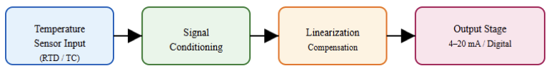
A temperature transmitter is an electronic device. It acquires an input signal from a temperature sensor.
RTDs or thermocouples are the typical sensors used. The transmitter converts this signal into a standardized output.
The output is sent to a controller or monitoring system. This allows temperature values to be read remotely. It also improves noise immunity.
Transmitters are used in process industries. Examples include oil and gas, power plants, and food processing.

Basic Calibration Concepts
Calibration compares an instrument to a reference. The reference must be more accurate. The difference between the two is the error. Calibration may include adjustment.
Verification-only calibration checks accuracy without adjustment. Traceability is essential. This means the reference is linked to national standards. Also, uncertainty must be known. Plus, calibration results should be documented.
Why Calibration Is Necessary
Calibration ensures measurement accuracy. No instrument remains accurate forever. Temperature transmitters drift due to component aging.
Vibration and thermal cycling also affect performance. Incorrect temperature readings can cause product defects.
They can also create safety risks. Regulatory standards often require periodic calibration. Calibration verifies that the transmitter output matches the true temperature. It also allows adjustment when errors exceed tolerance.
Temperature Sensors Used with Transmitters
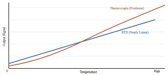
Temperature transmitters work with different sensors. RTDs are common in industrial applications.
They offer high accuracy and stability. Platinum RTDs like Pt100 are widely used. On the other hand, the thermocouples are also popular.
They cover a wide temperature range. Plus, they are rugged and simple. Each sensor type affects calibration. The transmitter must be calibrated for the correct sensor.

Calibration Standards and References
Accurate calibration requires reliable references. Dry block calibrators are widely used. They provide stable temperature sources.
In addition, liquid baths are used for high-accuracy work. Reference thermometers measure the true temperature.
These may be standard RTDs or precision thermometers. Electrical simulators can also be used. They simulate sensor signals directly. This is common for bench calibration.
What is temperature transmitter calibration?
Calibration is the process of comparing the performance of a device against a known standard. For a temperature transmitter, this involves two distinct steps. First, we test the sensing element, such as an RTD or thermocouple.
Second, we test the transmitter’s ability to convert that sensor data into a standardized output. Currently, most technicians perform a loop calibration.
This tests the entire measurement chain. Usually, from the heat source to the control room display.
If both the transmitter and the standard read 100°C, the system is within tolerance. Any deviation requires adjustment to align the transmitter with the reference.
Types of Temperature Transmitter Calibration
Calibration can be done in different ways. In-situ calibration is performed in the field. The transmitter remains installed.
While bench calibration is done in a workshop. Loop calibration checks the entire measurement loop.
Point calibration checks specific temperatures. And multi-point calibration checks linearity. Two-point calibration is common. It is used to check zero and span.
Calibration Range and Span
The calibration range is the temperature interval tested. The span is the difference between the upper and lower limits. Calibration should cover the operating range. Testing outside the range is not useful.
Zero corresponds to the lower range value. Span corresponds to the upper range value. Errors at zero and span affect the entire range.
Common Calibration Equipment
To perform a professional calibration, specialized equipment is required. A temperature standard, such as a dry-block calibrator or a stirred liquid bath, is used to provide a stable and known temperature reference.
A reference thermometer is also necessary, typically a high-accuracy probe like a Platinum Resistance Thermometer, which serves as the master measurement for comparison.
In addition, a process calibrator is used to measure the 4–20 mA output signal from the transmitter.
For smart transmitters, a HART or Fieldbus communicator is required to adjust internal parameters and complete the calibration process accurately.

Calibration Procedure Overview
Calibration follows a structured process. First, review transmitter specifications. Check the sensor type and range.
Inspect the transmitter physically. Apply power and allow warm-up. Apply known temperature points.
Measure the output at each point. Compare results with expected values. Then, adjust if necessary. Repeat measurements after adjustment and document all results.
Step-by-Step Calibration Example
A Pt100 temperature transmitter operates over a range of 0 to 100 °C and provides a 4–20 mA output signal.
Insert the sensor into a dry block. Set the dry block to 0 °C and allow stabilization. Measure the output current.
The latter should be 4 mA. Record the value. Increase the temperature to 100 °C. Allow stabilization. Measure the output again.
This should be 20 mA. Adjust zero or span if needed. To confirm accuracy, the process must be repeated.
Smart Temperature Transmitter Calibration
Smart transmitters use digital communication. Protocols include HART and Modbus. And calibration can be done via software. Sensor trimming and output trimming are possible.
Sensor trimming aligns the input measurement. Output trimming aligns the analog output.
Some transmitters store calibration data internally. This improves traceability. Smart calibration is faster and more precise.
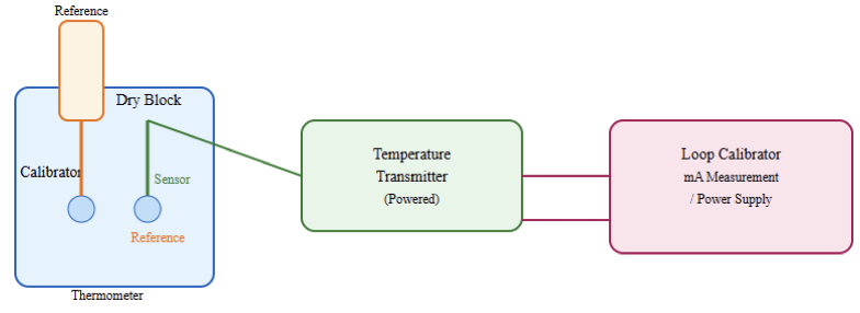
Loop Calibration
Loop calibration checks the entire signal path. This includes the transmitter, wiring, and control system. A loop calibrator injects or measures signals.
This verifies that the controller reads correctly. Loop calibration is useful for troubleshooting. It ensures system-level accuracy.
Sources of Calibration Errors
Several factors cause calibration errors. Temperature instability is common. Poor thermal contact affects readings.
In addition, electrical noise can disturb measurements. While incorrect reference accuracy causes bias.
Wiring resistance affects RTD signals. Cold junction compensation affects thermocouples. Human error is also significant. Proper procedure reduces these errors.
Environmental Effects on Calibration
Ambient conditions such as temperature and humidity matter. The affect electronic components and devices. Also, vibration can cause unstable readings. Air drafts affect dry block stability.
So, calibration should be done in controlled conditions. Allow sufficient stabilization time. Do not forget to avoid touching sensors during calibration.
Calibration Frequency
Calibration frequency depends on the application. When it comes to critical processes, frequent calibration is needed. But stable systems need less frequent checks. So, following manufacturer recommendations is a must.
Regulatory requirements may apply. Historical data helps determine intervals. Drift trends can be analyzed.
Documentation and Records
Calibration results must be recorded. Records include date and technician name. Equipment used must be listed. Reference serial numbers are important. Measured values and errors are recorded.
Pass or fail status is noted. Adjustment details should be included. Proper records support audits.
Standards and Guidelines
Several standards guide calibration. ISO 9001 requires measurement control. ISO/IEC 17025 defines calibration competence.
IEC standards cover temperature measurement. Industry-specific standards may apply. Using recognized standards guarantees consistent and high-quality results.
Temperature Transmitter Calibration: Best Practices
Always use traceable references. Follow written procedures. Also, allow sufficient warm-up time. Use appropriate calibration points. Plus, avoid unnecessary adjustments.
Verify results after calibration. Train personnel properly and regularly the calibration equipment should be maintained.
Diagnosing Calibration Problem
Some transmitters fail calibration. Wiring and connections should first be checked properly.
Verify sensor type settings. Inspect for damaged sensors. Checking power supply stability is crucial.
Reference accuracy must be confirmed. Replace faulty components if needed. Forcing adjustment beyond the limit is a bad practice. So not force adjustments beyond limits.
Safety Considerations
Calibration involves hot and cold surfaces. The risk of burns and frostbite is present. Also, electrical hazards may exist.
Hence, use proper personal protective equipment. Follow lockout procedures when required. It is recommended to ensure safe handling of equipment.
Applications Requiring High Accuracy
Most of the industry’s high accuracy is not an option; it is a must. The vivid example is pharmaceutical manufacturing.
Food processing also requires precision. Power generation depends on accurate temperature control.
Chemical reactions are temperature sensitive. Proper calibration supports these applications.
Automation and Calibration Management
Calibration management systems are used widely. Their main function is to schedule calibration tasks. Also, to store calibration records.
They generate reports automatically. Integration with asset management systems is common. This improves efficiency and compliance.
Key takeaways: Temperature Transmitter Calibration
This article details temperature transmitter calibration in detail. It addressed principles, equipment, procedures, errors, and best practices. Accurate temperature measurement requires correct transmitter calibration.
It ensures accuracy, safety, and compliance. Drift and environmental effects make calibration necessary.
Proper equipment and procedures are required. Understanding sensors and transmitters is important.
Documentation and standards support quality systems. Regular calibration prevents costly errors.
Following best practices improves confidence in measurements. As technology advances, calibration methods will continue to improve.
Accurate temperature measurement will remain a critical requirement in industrial systems.
FAQ: Temperature Transmitter Calibration
What is temperature transmitter calibration?
Calibration is the process of comparing the transmitter’s output to a traceable reference standard to determine measurement error and, if necessary, make adjustments so that the output accurately reflects true temperature values.
Why do I need to calibrate a temperature transmitter?
Transmitters drift over time due to aging, vibration, and environmental effects. Calibration ensures accuracy, process control, safety, and compliance with quality or regulatory standards.
How often should a temperature transmitter be calibrated?
There is no universal interval. Frequency depends on how critical the process is, environmental conditions, historical drift data, and any applicable standards or industry requirements. Many industries perform calibration annually or more frequently for critical systems.
What tools are used for calibration?
Common equipment includes dry-block calibrators, precision resistance simulators (for RTDs), millivolt simulators (for thermocouples), and loop calibrators to check 4–20 mA outputs.
Can I calibrate just the transmitter electronically?
Yes. Transmitter-only calibration simulates the sensor input (resistance for RTDs, millivolts for thermocouples) and checks that the analog output corresponds correctly to the input.
Should I calibrate the sensor and transmitter together?
For the highest accuracy, calibrate the full system (sensor + transmitter) under real temperature conditions. This accounts for the entire measurement chain.
How many calibration points should be used?
Best practice uses at least 3–5 evenly spaced points across the range (e.g., 0%, 25%, 50%, 75%, 100%) to verify linearity and accuracy through the span.
