What is PT-100, and how does it work?

PT-100 sensors are widely used for temperature measurement. They are highly accurate and reliable in industrial applications. PT-100 belongs to the resistance temperature detector family. 

Its resistance changes proportionally with temperature variations. Industries rely on PT-100 for critical process control systems. These sensors operate in hazardous and safe environments alike. PT-100 is easy to integrate, durable and most importantly, is simple.

It provides precise temperature readings over a wide range. Maintenance is minimal due to its robust design.

PT-100 can measure extreme temperatures effectively. They are preferred over thermocouples in many applications.

PT-100 sensors enable better process efficiency and safety. This article reviews PT-100, its working principle, and applications.

What is PT-100?

The name PT100 reveals its core technical specs. “PT” stands for the metal platinum inside it.

A PT-100 is a type of RTD sensor, in which the RTD signifies Resistance Temperature Detector. PT indicates platinum as the sensing material. 

100 refers to resistance in ohms at 0°C. Its resistance rises with increasing temperature. Platinum is chosen for stability and linearity.

PT-100 sensors can operate from -200°C to 850°C. They are more accurate than thermocouples in low ranges. Industries like chemical and food use PT-100 extensively.

Construction of PT-100

PT-100 has a platinum wire or film element. The element is wound or deposited on a ceramic.

Ceramic or glass provides electrical insulation. The sensor is protected with a stainless steel sheath. 

The sheath allows insertion into pipes or tanks. Insulating materials prevent short circuits inside the sensor.

Lead wires connect the sensor to measuring instruments. Three types of configurations are available in PT-100, which are two, three, or four connecting wires.

Types of PT-100 Sensors

There are mainly three PT-100 sensor types. First is the wire-wound type for high accuracy.

Second is the thin-film type, cost-effective and compact. Third is a coiled element, flexible for small spaces. 

The two-wire PT-100 is the simplest and least precise. Three-wire PT-100 compensates for lead resistance.

Four-wire PT-100 offers the highest accuracy in measurements. Selection depends on accuracy, installation, and budget.

Working Principle

PT-100 operates based on the resistance-temperature relationship. Platinum resistance grows proportionally as temperature rises.

The resistance at 0°C is 100 Ohms, and the temperature coefficient is around 0.00385 Ω/Ω/°C.

Measuring resistance allows calculation of sensor temperature. External circuits measure the voltage across PT-100. Instruments convert voltage into readable temperature values. 

The sensor does not produce its own voltage. PT-100 provides continuous and stable temperature monitoring.

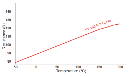
Diagram showing resistance vs temperature graph

The Linear Coefficient of Platinum 

Scientists use a specific value called “Alpha.” For most PT100s, Alpha is 0.003851. This represents the change in resistance per degree. Every degree Celsius adds 0.3850 Ohms of resistance. 

This linear behavior simplifies the math for controllers. You do not need complex curves for calculation.

Small changes in heat create measurable electrical shifts. This allows for extremely precise temperature control.

PT-100 Calibration

Calibration ensures accurate temperature readings. Sensors are compared against standard reference thermometers.

Ice point (0°C) and boiling point (100°C) calibrations are common. Three-point calibration improves accuracy further. 

Calibration adjusts measuring instruments, not the sensor itself. Regular calibration maintains sensor precision over time.

Industrial standards recommend calibration frequency annually. Calibration data helps in process quality control.

Configuration Methods

PT-100 can be connected in several ways. A two-wire connection is the simplest, with two leads.

The resistance of wires affects measurement accuracy. A three-wire connection compensates for lead resistance automatically. 

A four-wire connection is most accurate, ideal for precise applications. Instruments measure voltage across two opposite leads.

Connections are chosen based on distance and the accuracy required. Proper connection ensures reliable temperature readings.

Two-Wire PT100 Configuration

The 2-wire setup is the most basic style. It uses two leads to connect the sensor. It does not account for wire resistance.

This leads to inaccurate readings over long distances. You should only use it for short runs. 

Or use it where high precision is unnecessary. It is the cheapest option for simple tasks. Most industrial users avoid this specific configuration.

Three-Wire PT100 Configuration

The 3-wire setup is the industrial standard today. It adds a third wire to the circuit. Two wires carry the main excitation current. The third wire acts as a sense lead. The bridge circuit calculates the lead resistance.

It then subtracts that value from the total. This removes the error caused by the cable. It balances accuracy with cost and complexity. Because of this issue, most PLCs are designed for 3-wire inputs.

Four-Wire PT100 Configuration

The 4-wire setup provides the highest precision possible. It is mainly used in laboratory environments.

Two wires provide a constant current source. The other two wires measure the voltage drop. 

Since no current flows through the sense leads, resistance is zero. This eliminates all lead wire errors.

It is the gold standard for calibration work. However, it requires more expensive cabling and inputs.

Signal Conditioning

PT-100 requires signal conditioning before processing. The voltage drop across the sensor is small.

Instrumentation amplifiers enhance small signals. Wheatstone bridge configuration improves measurement accuracy. 

Analog-to-digital converters digitize the sensor signal. Signal conditioners filter noise and interference.

Accurate conditioning ensures precise process control. Some systems use transmitters to convert signals. Transmitters provide standard output like 4–20 mA.

Tolerance Classes and Accuracy

PT100 sensors come in different accuracy grades. These are known as “Tolerance Classes.” Class B is the standard industrial grade. It has an error of ±0.3°C at zero. 

Class A is much more precise. It offers an error of only ±0.15°C. There are also 1/10th DIN ultra-precise sensors. Better accuracy usually means a higher price tag. Always check your process requirements before buying.

PT100 vs. Thermocouples

There has always been confusion between PT100s and thermocouples. Thermocouples measure the voltage generated by two metals. They are faster and handle higher heat. However, PT100s are far more stable over time. 

They do not drift as much as thermocouples. PT100s provide much better accuracy at lower ranges.

If you need precision, choose the PT100. If you need extreme heat, choose thermocouples.

Applications of PT-100

PT-100 is widely used in many industries. Chemical plants monitor the temperature of reactors.

Food industries control cooking or freezing processes. HVAC systems maintain comfortable indoor conditions. 

Pharmaceutical industries monitor incubators and storage rooms. Power plants measure boiler and turbine temperatures.

PT-100 is suitable for laboratory experiments. Industrial automation systems rely on PT-100 readings.

Advantages of PT-100

PT-100 is accurate and reliable for temperature measurement. It has high repeatability over a wide range.

Long-term stability reduces maintenance requirements. Platinum material ensures chemical and corrosion resistance. 

Sensor responds quickly to temperature changes. Available in various designs for different environments.

Can integrate with PLCs and control systems easily. Cost-effective for high-accuracy applications in industry.

Limitations of PT-100

If there is the existence of mechanical vibrations and shocks, the PT-100 becomes sensitive to them.

High initial cost compared to thermocouples. Requires careful wiring to avoid errors. Limited maximum temperature compared to some thermocouples. 

Signal conditioning is needed for long distances. Fragile thin-film sensors may break easily.

Maintenance in harsh conditions may still be required. Proper installation avoids most limitations.

How to Test a PT100

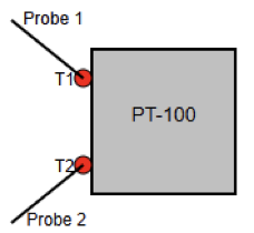
A PT100 can be tested by using a multimeter. Set the meter to the ohms setting. Join the probes with the sensor terminals.

At room temperature, it should read   Ohms. At zero degrees, it must read   Ohms. If the reading is infinite, it is broken. If the reading is zero, it is shortened. This simple test confirms the sensor is healthy.

Key takeaways: What is PT-100, and how does it work?

This article demonstrated PT-100 sensors and their working principle. PT-100 provides accurate and stable temperature measurement.

Its construction, types, and wiring influence performance. Calibration and signal conditioning improve precision further.

Industries rely on PT-100 for critical process monitoring. Proper installation ensures long sensor life and reliability.

PT-100 remains a standard in modern industrial applications. They offer consistent performance in harsh environments. 

Sensor selection depends on accuracy and application needs. PT-100 contributes to automation and safety in industries.

Future technologies may enhance PT-100 integration with smart systems. Overall, PT-100 is essential for precise and reliable temperature measurement worldwide.

FAQ: What is PT-100, and how does it work?

What does PT-100 mean?

PT refers to platinum. Material used to build the sensor. And 100 refers to 100 Ω resistance at 0 °C.

What type of sensor is a PT-100?

It is a Resistance Temperature Detector (RTD). It measures temperature by monitoring resistance changes.

How does a PT-100 measure temperature?

Platinum resistance rises as temperature increases. The resistance change follows a standardized curve.

What is the temperature-resistance relationship?

At 0 °C, the sensor reads 100 Ω, while at 100 °C, the resistance is about 138.5 Ω.

Why is platinum used?

Platinum provides high accuracy and stability. It is chemically stable and reproducible over time.


What Is an Intrinsic Safety Barrier?

Hazardous environments containing flammable substances are always present where industrial facilities operate. Serious ignition risks are presented by electrical equipment installed in these areas.

Even small electrical sparks may ignite either combustible dust, vapors, or gases. To reduce these dangers, specialized protection methods are required. Intrinsic safety is one widely accepted explosion protection technique. 

This method focuses on limiting energy rather than containing explosions. Intrinsic safety barriers play a crucial role in this approach. They restrict electrical energy before it reaches hazardous locations. 

These devices allow safe operation of instrumentation systems. Industries worldwide rely on intrinsic safety barriers. Understanding their function improves system reliability and safety. 

This article reviews intrinsic safety barriers, their principles, and types. It also explains their applications, standards, and finally, practical considerations.

Concept of Intrinsic Safety

Preventing ignition under all conditions is the main idea behind intrinsic safety. The principle ensures energy levels remain below ignition thresholds. Both electrical and thermal energies are carefully limited. 

This limitation applies during normal operation and fault conditions. Possible faults include short circuits and component failures. Intrinsic safety differs from explosion-proof protection methods.

Instead of containing explosions, it prevents them entirely. This approach significantly improves operational safety.

Maintenance activities can occur without shutting down processes. As a result, intrinsic safety improves both safety and productivity.

What Is an Intrinsic Safety Barrier?

An intrinsic safety barrier is a protective interface device. It is installed between safe and hazardous areas.

The barrier controls energy entering dangerous locations. Voltage and current are limited to safe values. This prevents sparks and excessive heating. 

Field instruments remain protected during faults. Intrinsic safety barriers are certified safety components.

They must meet strict international standards. Proper selection and installation are essential, and incorrect use may compromise system safety.

Purpose of Intrinsic Safety Barriers

It just needs a minimum amount of energy to ignite hazardous atmospheres. Electrical circuits naturally produce sparks and heat.

Without protection, these sources pose serious risks. Intrinsic safety barriers eliminate this ignition potential. 

They restrict energy during both normal and abnormal conditions. Personnel safety is significantly enhanced.

Equipment damage is also greatly reduced. Regulatory authorities require such protection methods.

Barriers simplify compliance with safety regulations. They provide a reliable and proven safety solution.

Operating Principle of Intrinsic Safety Barriers

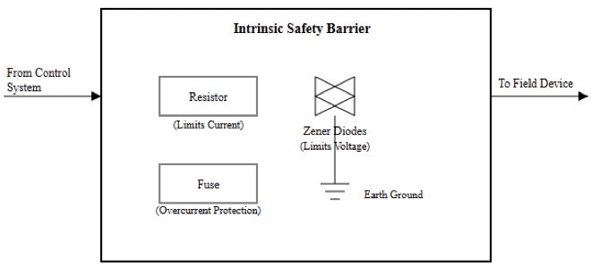
Intrinsic safety barriers operate by controlling electrical energy. They limit voltage, current, and stored energy.

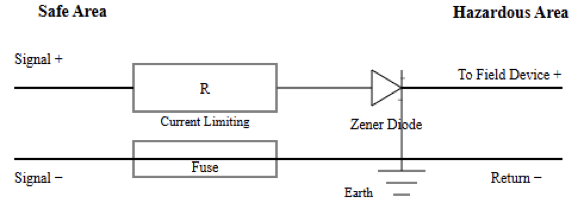
This is achieved using specific protective components. Resistors restrict excessive current flow. Zener diodes clamp voltage to safe limits.

Fuses disconnect circuits during severe faults. These components work together continuously.

Energy entering hazardous areas remains non-incendive. The operating principle is simple but effective.

Internal Components and Construction

Intrinsic safety barriers contain carefully selected components. Resistors are used for current limitation.

Zener diodes provide voltage clamping protection. Fuses offer final fault protection. Ground terminals ensure proper voltage reference. 

Protective enclosures shield internal components. Each component must be safety certified.

Long-term reliability can be improved by high-quality construction. Component failure can compromise intrinsic safety. Therefore, strict manufacturing standards are applied.

Types of Intrinsic Safety Barriers

Intrinsic safety barriers are available in different types. The two primary categories are passive and active barriers.

Passive barriers are commonly called Zener barriers. Active barriers are known as galvanic isolators. Each type serves specific application needs. 

Selection depends on system design and requirements. Understanding their differences is essential.

Incorrect selection may introduce safety risks. Engineers must evaluate each application carefully.

Zener Barriers

Zener barriers are passive intrinsic safety devices. They rely on resistors and Zener diodes. Excess voltage is diverted to a safety ground. This grounding path is essential for protection. 

Zener barriers are simple to use and financially efficient. They are widely used in many installations.

However, grounding integrity is critical. Poor grounding reduces their effectiveness. Regular grounding inspections are required.

Galvanic Isolators

Galvanic isolators are active intrinsic safety barriers. They use transformers or opto-isolators internally.

There is no direct electrical connection between zones. This provides inherent electrical isolation. Grounding requirements are less restrictive.

Signal accuracy is usually better. Noise interference is significantly reduced. Galvanic isolators are more expensive. Their advantages often justify the higher cost.

Comparison Between Barrier Types

Zener barriers require a high-integrity safety ground. Galvanic isolators operate without such grounding.

Isolators provide superior signal quality. Zener barriers offer simpler installation and lower cost. 

System complexity influences the selection decision. Both barrier types meet intrinsic safety standards. Proper evaluation ensures safe and reliable operation.

Hazardous Area Classification

Special standards are used to classify hazardous areas. These classifications define ignition risk levels.

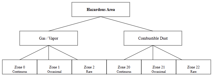
Zone Zero represents continuous hazardous presence. Zone One indicates occasional hazardous conditions. 

Zone Two represents rare hazardous occurrences. Barriers must be rated for the specific zone.

Incorrect classification leads to unsafe installations. Compliance with standards is mandatory.

Gas Groups and Temperature Classes

Different gases ignite at different energy levels. Gas groups categorize explosion severity. Temperature classes limit maximum surface temperatures. Equipment must remain below these limits. 

Intrinsic safety barriers must match gas group ratings. Temperature compliance prevents hot surface ignition.

Incorrect ratings may cause dangerous conditions. Standards clearly define these requirements.

Standards and Certification Requirements

Intrinsic safety systems follow international standards. IEC 60079 governs intrinsic safety worldwide. ATEX directives apply within European regions. North America uses NEC and NFPA standards. 

Certification ensures equipment meets safety requirements. Documentation must match installed components. Inspectors verify compliance during audits. Certified systems reduce legal and operational risks.

Typical Applications

Intrinsic safety barriers are used across industries. Oil and gas facilities rely on them heavily.

Chemical plants use intrinsic safety instrumentation. Pharmaceutical production requires precise, safe measurements. 

Mining operations face explosive dust hazards. Water treatment facilities also apply intrinsic safety.

These applications demand reliable protection. Barriers provide proven safety performance.

Installation Considerations

Correct installation is critical for intrinsic safety. Barriers must be installed in safe areas. Wiring practices must follow approved standards. Cable segregation prevents unintended energy transfer. 

Grounding must meet manufacturer specifications. Labels help identify intrinsically safe circuits.

Poor installation compromises system safety. Strictly following the installation guidelines helps to solve this situation.

Maintenance and Inspection

Routine inspection is always required in intrinsic safety systems. Connections must remain secure and undamaged.

Ground resistance should be checked regularly. Damaged components must be replaced immediately. 

System modifications require documentation updates. Regular maintenance preserves certification validity. Neglect increases safety risks significantly.

Advantages of Intrinsic Safety Barriers

Intrinsic safety barriers provide reliable explosion prevention. Maintenance can occur without shutting down processes. Installation costs are often lower. System flexibility is improved significantly.

Explosion-proof enclosures become unnecessary. Operational uptime increases. Safety performance remains consistently high.

Limitations of Intrinsic Safety

Intrinsic safety limits available electrical power. High-power devices cannot use this method. Cable parameters must be carefully calculated.

System design requires engineering expertise. Incorrect calculations reduce safety margins. Despite limitations, intrinsic safety remains effective.

Key Takeaways: What Is an Intrinsic Safety Barrier?

This article demonstrated how intrinsic safety barriers prevent ignition in hazardous environments.

Intrinsic safety barriers are essential industrial safety devices. They limit energy entering hazardous environments. Proper selection ensures reliable explosion prevention. 

Understanding barrier types improves system design quality. Correct installation prevents ignition risks effectively. Compliance with standards ensures legal operation.

Industries benefit from improved safety and reliability. Intrinsic safety remains a trusted protection method worldwide.

FAQ: What Is an Intrinsic Safety Barrier?

What is an intrinsic safety barrier?

A device that is used to limit energy to prevent sparks in hazardous areas.

Why is it used?

To stop electrical energy from igniting gaseous dust, vapors, or gases.

How does it work?

Uses fuses, Zener diodes, and resistors to restrict voltage and current.

Where is it installed?

In the safe area, between control systems and field devices.

Does a barrier alone make a system safe?

No, the entire loop must comply with intrinsic safety requirements.

Types of barriers?

  • Zener (passive) barriers
  • Galvanically isolated barriers

Thermocouple Working Principle

Temperature measurement plays a critical role in engineering systems. Process stability and efficiency can be ensured by a correct temperature.

So, this provides safety. Many industrial processes depend on reliable temperature sensing devices. 

Thermocouples are among the most widely used temperature sensors. They are valued for wide temperature capability, durability, and simplicity. Thermocouples operate based on a fundamental thermoelectric phenomenon. 

This phenomenon converts temperature differences into measurable electrical voltage. No external power source is required for thermocouple operation. They function reliably under harsh industrial environments. 

Corrosive conditions, vibrations, and high temperatures do not easily damage them. Technicians and engineers need to understand the thermocouple working principle. Correct knowledge ensures accurate measurements and proper sensor selection. 

This article explains thermocouple operation, construction, characteristics, and their applications in industry.

Basic Concept of Thermocouples

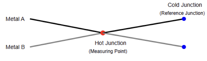
A thermocouple uses two unlike metallic wires. These wires are joined together electrically at one end.

The joint point is called the measuring junction. The free ends connect to a measuring instrument. When a temperature difference exists, a small electrical voltage appears.

This voltage depends on the metals used. Thermocouples measure temperature indirectly using voltage generation.

The measured voltage represents the temperature difference. Proper interpretation converts voltage into temperature values.

Seebeck Effect and Its Role

Thermocouples operate based on the Seebeck effect. This outcome explains a relationship between heat and magnetism. German physicist Thomas Seebeck discovered this thermoelectric phenomenon. 

It occurs when dissimilar conductors form a closed circuit. A temperature gradient causes charge carriers to move. This movement generates an electromotive force within conductors. 

The resulting voltage is proportional to the temperature difference. Each metal pair has a unique Seebeck coefficient. This coefficient determines thermocouple sensitivity and output characteristics.

Hot Junction and Cold Junction Concept

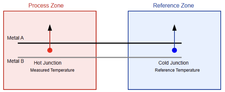
Thermocouples contain two essential temperature junctions. The hot junction senses the process temperature directly.

It is placed inside the measurement environment. The cold junction serves as the reference junction. It remains at a known reference temperature. 

Voltage develops due to the temperature difference between junctions. Accurate reference temperature ensures reliable measurements. Modern instruments compensate for reference temperature electronically.

Cold Junction Compensation

Cold junction compensation is required for accurate thermocouple readings. It corrects errors caused by reference temperature variations.

Earlier systems used ice baths as reference junctions. Modern systems use electronic temperature sensors instead. 

Compensation circuits adjust the measured thermocouple voltage. This adjustment ensures correct temperature calculation.

Without compensation, significant measurement errors occur. Digital instruments perform compensation automatically.

Thermocouple Voltage Generation Characteristics

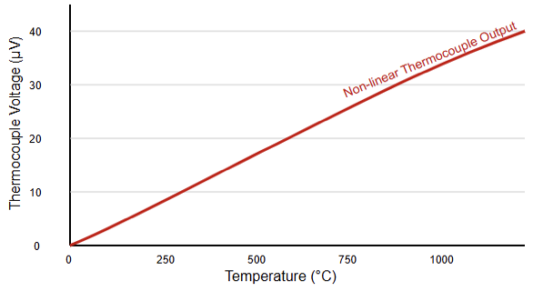
In general, a very small number of electrical voltages is generated by thermocouples. Typical outputs are in microvolt ranges.

Voltage increases as the temperature difference increases. Each thermocouple type produces characteristic voltage curves. These curves are nonlinear across temperature ranges. 

Signal conditioning improves measurement accuracy significantly. Amplifiers increase voltage to measurable levels. Filtering reduces electrical noise interference.

Common Thermocouple Types

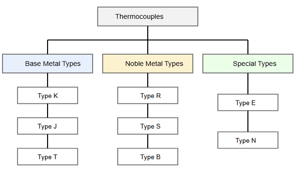
Many standardized thermocouple types are widely used worldwide. Each type uses specific metal combinations.

Type K uses nickel-chromium and nickel-aluminum materials. Type J uses iron and constantan metals. 

Type T uses copper and constantan conductors. Types R and S use platinum alloys. Each type supports specific temperature ranges. Material choice affects accuracy and longevity.

Materials and Construction

Thermocouple materials are selected for long-term stability and must withstand high temperatures and oxidation effects.

Insulation prevents electrical short circuits between conductors. Common insulation materials include fiberglass and ceramic compounds. 

Protective sheaths improve mechanical strength significantly. Metal sheaths resist corrosion and vibration effectively.

Construction affects response time and durability. Proper selection ensures long-term reliable operation.

Measurement Circuit and Instrumentation

Thermocouples connect to specialized temperature-measuring instruments. These instruments convert voltage into temperature readings.

Analog meters display temperature using calibrated scales. Digital instruments use internal conversion algorithms. 

Microcontrollers apply polynomial approximations for conversion. Signal conditioning improves accuracy and stability.

Electrical isolation protects sensitive measurement circuits. Proper grounding reduces electrical noise problems.

Accuracy and Sensitivity Considerations

The accuracy of a thermocouple depends on multiple influencing factors. Material purity strongly influences output stability.

Junction quality affects thermal response accuracy. Cold junction compensation accuracy is essential. 

Long-term measurement reliability can be improved by performing calibration. It has been proven that thermocouples are less accurate than RTDs.

However, they tolerate extreme temperatures better. Sensitivity varies depending on thermocouple type.

Response Time Characteristics

Generally, relatively fast response times are offered by all thermocouples. Smaller junctions respond faster to temperature changes.

Sheathed probes respond more slowly due to thermal mass. Response time depends on construction and environment. 

Bare junctions provide the fastest measurements. However, they offer minimal mechanical protection.

Engineers balance speed and durability requirements. Application determines optimal probe selection.

Advantages of Thermocouples

Thermocouples operate over extremely wide temperature ranges. They require no external power supply.

Their construction is simple and robust. They perform reliably in harsh environments. Thermocouples resist vibration and mechanical shock. 

They are relatively inexpensive sensors. Maintenance requirements remain minimal. They suit high-temperature industrial applications.

Limitations of Thermocouples

Thermocouples produce very low output voltages. This makes them susceptible to electrical noise interference. Accuracy is lower compared to RTDs. The output voltage is nonlinear with temperature. 

Cold junction compensation increases system complexity. Material aging causes long-term measurement drift.

Periodic calibration may be required. Signal conditioning increases overall system cost.

Industrial Applications

Many industries across the world use thermocouples in daily basis. They monitor furnace and kiln temperatures.

Power plants use them for turbine monitoring. Engines use thermocouples for exhaust measurements. 

Steel manufacturing requires high-temperature thermocouples. Chemical processes rely on temperature feedback.

Food processing equipment uses thermocouple sensors. Aerospace systems also depend on thermocouples.

Comparison with Other Temperature Sensors

Thermocouples differ significantly from thermistors and RTDs. Thermistors provide high sensitivity at low temperatures.

RTDs offer higher accuracy and stability. Thermocouples are suitable in operation where much higher temperatures are involved. 

They withstand harsher operating environments. Response time is generally faster. Sensor choice depends on application requirements. Cost and durability influence selection decisions.

Installation and Best Practices

Proper installation ensures accurate temperature measurement results. Avoid sharp bends near the junction.

Use correct extension and compensation cables. Also, ensure good thermal contact with surfaces. 

One of the very unwanted disruptions in an electronic circuit is electromagnetic interference (EMI).

Hence, wires must be protected at all costs from this phenomenon. Also, avoid mixing different thermocouple materials.

Follow the manufacturer’s installation recommendations carefully. Regular checks enhance reliability over extended periods.

Calibration and Maintenance

Calibration verifies thermocouple measurement accuracy periodically. Reference temperature sources are used for calibration.

Periodic calibration compensates for material drift. High temperatures accelerate aging effects. 

Maintenance includes checking the insulation condition regularly. Damaged probes should be replaced promptly. Clean junctions improve thermal contact. Documentation ensures traceability and compliance.

Key takeaways: Thermocouple Working Principle

This article reviewed the thermocouple working principle thoroughly. Thermocouples are essential temperature measurement devices.

They operate using the Seebeck thermoelectric effect. Two dissimilar metals generate voltage from temperature differences. 

Their simple design enables widespread industrial use. They perform reliably in extreme temperature environments.

Despite limitations, their advantages remain significant. Proper selection ensures accurate and stable measurements. 

Understanding their working principle improves engineering decisions. Thermocouples are, and will remain, vital in industrial instrumentation systems.

FAQ: Thermocouple Working Principle

What is a thermocouple?

A thermocouple is a temperature sensor made from two dissimilar metal wires joined at a junction.

How does a thermocouple work?

It generates a small voltage proportional to the temperature difference between two junctions. 

What principle explains thermocouple operation?

Thermocouples operate based primarily on the Seebeck effect. 

What is the Seebeck effect?

When two dissimilar metals form a junction and experience a temperature difference, a thermoelectric voltage (EMF) is produced. 

Does a thermocouple measure absolute temperature?

Not directly, it measures the difference between the hot junction and a reference (cold) junction.

What is the “hot junction”?

The hot junction is the point where the two different metals are joined and exposed to the measured temperature.

Types of Limit Switches

Limit switches are vital devices in industrial automation. They detect the position, presence, or movement of machine parts.

These devices convert mechanical action into electrical signals. Industries rely on them for control and safety. 

They help prevent collisions and mechanical damage. Limit switches improve the reliability of automated systems.

They are simple, rugged, and highly dependable components. Modern factories still depend on these classic devices. 

They operate under harsh environmental conditions reliably. They support precise motion control in many applications.

Different designs exist for different operational needs. Understanding types helps engineers select suitable devices.

This article reviews the main types of limit switches, their operation, and their industrial applications.

Basic Working Principle

A limit switch uses physical contact for actuation. An external object applies force to an actuator.

Internal contacts change state after actuation. This change sends an electrical control signal. The signal starts, stops, or reverses motion. 

Springs return actuators after force removal. Contacts may be normally open or closed. Simple construction ensures long operational life. 

Classification of Limit Switches

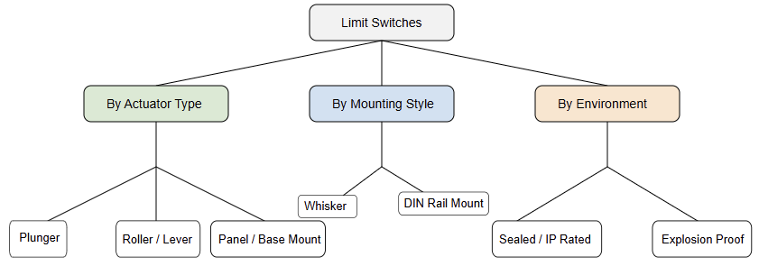
Limit switches are classified by actuator design. They are also classified by mounting style. Contact configuration offers another classification method.

Environmental ratings further differentiate switch types. Application requirements guide the final classification choice. 

Plunger-Type Limit Switches

Plunger limit switches use linear actuator motion. A moving object presses the plunger directly.

Plunger movement triggers internal contact change. These switches offer high positional accuracy.

They suit applications with straight-line motion. Plungers withstand repeated mechanical impacts well.

Overtravel protection improves plunger switch durability. They require precise alignment during installation. 

Roller Plunger Limit Switches

Roller plunger switches reduce actuator friction significantly. A roller replaces the standard plunger tip. The roller follows moving parts smoothly. This design minimizes wear during operation. 

They handle side loads better than plungers. Roller plungers extend operational life considerably. They are common in conveyor systems. 

Lever Arm Limit Switches

Lever arm switches use pivoted mechanical arms. The arm moves when contacted by objects. Movement rotates internal cam mechanisms.

This rotation actuates the electrical contacts inside. Lever arms handle angular or lateral motion. 

They are flexible for varied actuation directions. Adjustable levers allow sensitivity modification. They suit packaging and material handling machines.

Roller Lever Limit Switches

Roller lever switches include rollers on levers. The roller reduces friction during actuation. They allow smooth engagement with moving surfaces. Rollers prevent damage to contacting objects. 

These switches handle continuous motion effectively. They are common in high-speed machinery. Roller levers reduce noise during operation. 

Whisker-Type Limit Switches

Whisker switches use flexible wire actuators. Thin metal whiskers detect light contact. They require minimal actuation force.

Whiskers bend easily without mechanical damage. They suit delicate or lightweight components. Sensitivity makes them ideal for detection tasks. They are less suitable for harsh impacts. 

Rotary Limit Switches

Rotary limit switches respond to angular motion. A rotating shaft drives internal cams. Cams actuate contacts at set angles. These switches monitor rotational position accurately. 

They control cranes, hoists, and elevators. Multiple contacts enable multi-position control. They support complex sequencing operations.

Heavy-Duty Limit Switches

Heavy-duty limit switches handle extreme conditions. They feature robust housings and strong actuators. These switches resist shock and vibration. They operate reliably in dirty environments. 

Metal enclosures provide mechanical protection. They are used in the steel and mining industries. Long service life reduces maintenance requirements. 

Miniature Limit Switches

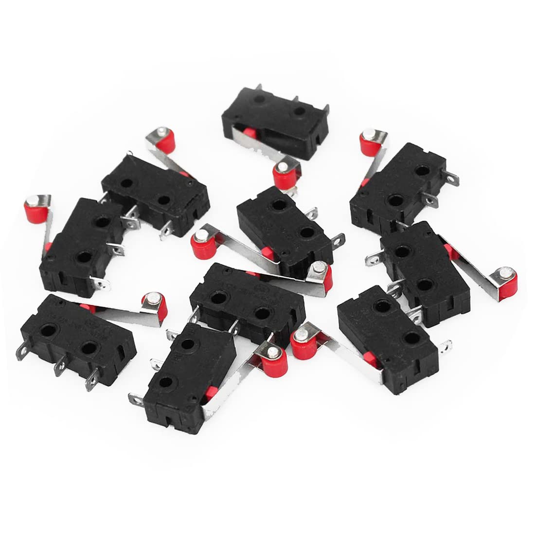
Miniature limit switches fit compact installations. They offer similar functions in smaller sizes. These switches suit space-constrained equipment. Despite size, reliability remains high. 

They operate with lower actuation forces. Miniature designs support precise sensing tasks. They are common in electronics manufacturing. 

Sealed Limit Switches

Sealed limit switches prevent contaminant entry. They use gaskets and tight enclosures. One of the very important tasks of sealing is protection against moisture and dust. They perform well in washdown environments. 

Ingress protection ratings define sealing effectiveness. Sealed switches extend service life significantly. They suit the food and pharmaceutical industries. 

Explosion-Proof Limit Switches

To operate in hazardous areas, a special kind of limit switch called an explosion-proof switches are used.

They contain sparks within robust housings. These switches prevent ignition of flammable gases. They meet strict safety certification standards. 

Heavy casings withstand internal explosions safely. They are critical in oil and gas plants. Proper installation ensures safe operation. 

Contact Configurations

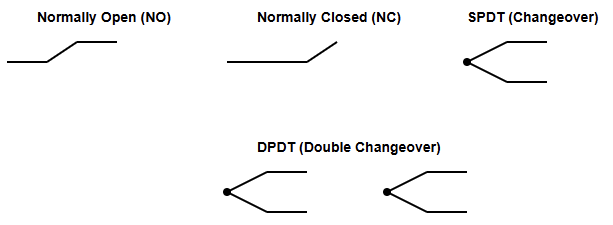
Limit switches offer various contact arrangements. Common types include SPDT and DPDT. Normally open contacts close upon actuation. Normally closed contacts open during actuation. 

Dual contacts provide redundancy and flexibility. Contact selection affects control logic design. 

Electrical Ratings

Electrical ratings define voltage and current limits. Exceeding ratings reduces switch lifespan significantly.

AC and DC ratings differ considerably. Proper rating selection ensures safe operation. Inductive loads require special consideration. Engineers must verify ratings before installation. 

Mounting Styles

Limit switches support various mounting options. Panel mounting allows easy accessibility.

Base mounting offers rigid mechanical support. DIN rail mounting simplifies control cabinet installation.

Mounting choice affects alignment and accuracy. Proper mounting reduces mechanical stress. 

Applications of Limit Switches

Limit switches appear across many industries. They control conveyor belt positions. They ensure safe machine travel limits.

Elevators rely on limit switches for safety. Packaging machines use them for positioning. Robotics systems depend on precise limit detection. They support automation and process reliability. 

Advantages of Limit Switches

Limit switches provide simple, reliable operation. They require minimal electronic complexity.

Mechanical actuation ensures clear signal states. They tolerate electrical noise well. Maintenance requirements remain relatively low.

They operate without external power sources. Cost-effectiveness benefits many applications. 

Limitations of Limit Switches

Mechanical contact causes eventual wear. High-speed systems may exceed response limits. Physical alignment is critical for reliability.

Repeated impacts reduce mechanical lifespan. Non-contact sensors sometimes offer better solutions. Application evaluation helps mitigate limitations. 

Selection Considerations

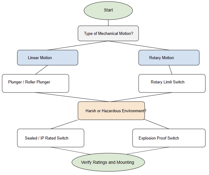
Proper selection depends on application conditions. Engineers must evaluate the mechanical movement type. Environmental factors influence enclosure choice.

Electrical load determines contact configuration. Mounting space limits switch dimensions. Safety requirements guide certification needs. 

Maintenance and Testing

Regular inspection ensures reliable limit switch operation. Check actuator alignment and physical damage.

Test contact continuity during maintenance routines. Replace worn components promptly when detected.

Clean actuators to prevent sticking issues. Preventive maintenance extends operational lifespan. 

Future Trends

Limit switches remain relevant despite sensor advances. Hybrid designs integrate mechanical and electronic sensing.

Smart switches provide diagnostic feedback signals. Industry still values mechanical reliability.

Cost-sensitive applications favor limit switches. They coexist with proximity sensor technologies. 

Key takeaways: Types of Limit Switches

This article depicted the structure, operation, and classification of limit switches used in industry.

Limit switches are fundamental industrial control devices. They provide reliable mechanical position detection. 

Many designs address diverse application requirements. Understanding types improves engineering decision-making.

Proper selection enhances safety and system performance. Despite new technologies, demand remains strong. Limit switches continue to support industrial automation worldwide.

FAQ: Types of Limit Switches

What is a limit switch?

A limit switch is a device that detects position or motion and sends an electrical signal.

Where are limit switches used?

They are used in industrial machines for position control and safety.

What are the main types of actuator?

Plunger, roller plunger, lever arm, roller lever, and whisker.

What is a plunger limit switch?

It uses a straight sliding stem to detect linear motion.

What is a roller plunger switch?

A plunger with a roller wheel to reduce friction.

What is a lever arm switch?

A pivot arm that moves when contacted by a machine part.

What Is a Fire Alarm System?

When it comes to protecting life and property, fire alarm systems play a critical role. They are designed to detect fire conditions early.

They also provide clear warnings to occupants. A well-designed system reduces panic and confusion. It also supports fast evacuation.

Fire alarm systems are used in public buildings, factories, offices, and homes. Each environment has different risks.

Because of this, several types of fire alarm systems exist. Each type has its own purpose and, without forgetting, its own structure. 

Understanding these systems helps engineers, technicians, and building owners. It also supports correct selection and maintenance.

This article reviews the main categories of fire alarm systems, their working principles, and typical applications.

What Is a Fire Alarm System?

A fire alarm system is an integrated safety system. It detects fire-related events. These events include smoke, heat, or flame.

The system then triggers audible and visual alarms. Some systems also notify emergency services. 

A basic system includes detectors, a control panel, and notification devices. Power supplies and wiring are also required.

Modern systems may include communication modules. They may also connect to building management systems.

The next figure illustrates a basic block diagram of a fire alarm system showing detectors, a control panel, and alarms.