What Is Industrial Cloud Computing?

Industrial systems are becoming more connected. They are also more data-driven and intelligent.

Traditional automation architectures rely on local control. They often use isolated networks. These approaches struggle with modern complexity.

Scale and speed are also limiting factors. Industrial cloud computing addresses these challenges.

It combines cloud technologies with industrial automation systems. This enables scalable storage and advanced analytics. 

It also supports remote access and system integration. Industrial cloud computing extends classical automation.

Smart manufacturing, as well as the Industry 4.0 initiative, is supported. This article explains the concept. It also covers architecture, components, use cases, benefits, and challenges.

Definition of Industrial Cloud Computing

Industrial cloud computing applies cloud technologies to industrial environments. These technologies include infrastructure, platforms, and software. Delivery is provided over the internet. Industrial environments include factories and utilities. 

They also include oil, gas, and water facilities. Industrial data has unique characteristics. Real-time behavior is often required.

Reliability expectations are high. Asset lifecycles are long. Safety and cybersecurity constraints are strict. 

Industrial cloud systems address these needs. They integrate operational technology with information technology. This bridges factory-floor devices and enterprise systems.

The next figure indicates a diagram of industrial cloud architecture. It shows field devices, controllers, edge gateways, industrial clouds, and enterprise applications.


What Is Industrial Cloud Computing

From Traditional Automation to Cloud-Based Systems

Historically, automation systems were isolated. Architectures were hierarchical. Sensors connected to PLCs or DCS controllers.

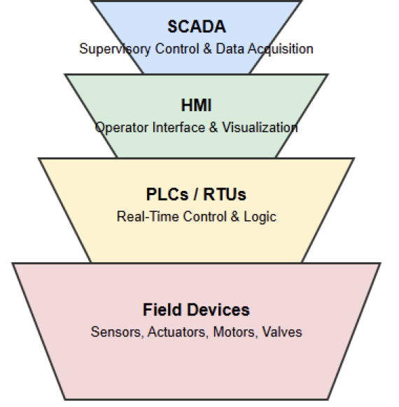
These systems are linked to HMI or SCADA platforms. Data was stored locally. Access was limited and proprietary.

IIoT technologies changed this model. Ethernet networks became common. Standard protocols improved interoperability.

Cloud computing added scalable resources. Storage and computing power became virtually unlimited. Organizations could centralize analytics and visualization.

Industrial cloud computing complements local control. It does not replace it. Real-time control remains on-site. Data-heavy tasks move to the cloud. This balances performance and flexibility.

Core Components of Industrial Cloud Computing

Industrial Devices and Control Systems

At the lowest level are field devices. These include sensors and actuators. Drives and soft starters are also present. PLCs and DCS controllers manage control logic.

These devices generate raw operational data. Examples include temperature and pressure. Electrical and status signals are common.

Edge Computing and Gateways

Edge devices sit between the plant and the cloud. They aggregate and preprocess data. Filtering and local analytics are performed. Deterministic behavior is preserved. Latency is reduced. Bandwidth usage is optimized.

System resilience improves. The upcoming figure illustrates a diagram of edge computing with local analytics before cloud transmission.


Cloud Infrastructure

The cloud layer provides scalable resources. It includes computing and databases. Networking services are also provided. Historical data is stored here. Advanced analytics are executed.

Machine learning models are supported. Deployment can be public or private. Hybrid options are also common.

Applications and Services

Cloud applications sit at the top layer. These include dashboards and asset management tools. A large number of uses exist out there.

Predictive maintenance, also known as PdM, is a vivid example. In addition, the management of energy platforms is included. Digital twins are also supported. Raw data becomes actionable insight.

Service Models in Industrial Cloud Computing

The Infrastructure as a Service

Also known as IaaS. Once well studied and understood, IaaS provides virtual infrastructure. Computing and storage are included.

Networking is also available, and industrial users host historians and data lakes. Physical servers are no longer required.

Platform as a Service

Shortly, PaaS supports application development. It includes databases and middleware. Data ingestion tools are provided. Analytics and visualization are simplified. Development time is reduced.

Software as a Service

This is a cloud-based model where software is centrally hosted and delivered to users. The whole process occurs over the internet, usually via a web browser, on a subscription basis, eliminating the need for local installation and maintenance. It is also called SaaS; it delivers ready-made applications. 

Access is provided through web interfaces. Condition monitoring is a common example. Production reporting is also included. Remote asset management is supported.

Deployment Models

Public Industrial Cloud

Public clouds are provider-managed. Resources are shared across customers. Scalability is high. Upfront costs are low. Data sovereignty may be a concern. Security requirements must be evaluated.

Private Industrial Cloud

Private clouds serve one organization. Control and customization are greater. Critical infrastructure benefits from this model. Regulatory compliance is easier.

Hybrid and Multi-Cloud

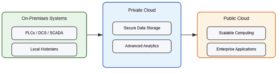
Hybrid models combine local systems and cloud services. Multi-cloud uses several providers.

Vendor lock-in is reduced. Resilience is improved. The following figure depicts a hybrid cloud linking on-premises systems with public and private clouds.

Use of Industrial Cloud Computing

Predictive Maintenance

Cloud analytics processes operational data. Failure patterns are identified early. Maintenance becomes proactive. Downtime is reduced. Costs are lowered.

Remote Monitoring and Operations

Assets can be monitored remotely. Engineers access systems from anywhere. Distributed facilities benefit greatly. Examples include pipelines and substations.

Energy Management

Energy usage is tracked centrally, and inefficiencies are identified. Data-driven is obviously a result of optimization. Multi-site visibility is achieved.

Quality and Process Optimization

Analytics detect process deviations. Quality issues are identified early. Continuous improvement is supported.

Benefits of Industrial Cloud Computing

Industrial cloud systems scale easily. Infrastructure investment is reduced. Decisions become data-driven.

Collaboration improves through centralized data. Remote access increases flexibility. Response time is reduced. Innovation accelerates.

Advanced tools like artificial intelligence (AI) are enabled. Without forgetting digital twins, as mentioned.

Challenges and Considerations

Latency must be controlled carefully. Time-critical functions need protection. Reliability is essential.

Cybersecurity is a major concern. Strong authentication is required. Encryption and segmentation are necessary.

Legacy integration can be complex. Regulatory and data ownership issues must be addressed.

Security in Industrial Cloud Computing

Industrial cloud security extends beyond IT. OT-specific threats must be addressed. Unauthorized control is a risk. Process manipulation is possible.

Defense-in-depth is commonly used. Secure devices are configured first. Networks are segmented. Communications are encrypted. Access is tightly controlled.

Future Trends

Industrial cloud adoption continues to grow. Digital twins are becoming widespread. Virtual factories are being developed.

Advanced optimization is emerging. New computing paradigms are explored. Cloud integration remains central to Industry 4.0. Smart factories depend on it. Asset lifecycle management improves.

Key Takeaways: Industrial Cloud Computing

This article addressed industrial cloud computing and its role. Architecture and service models were explained.

Deployment options and use cases were reviewed. Industrial cloud computing enhances traditional automation. 

It provides scalable storage and analytics. Global connectivity is enabled. Challenges must be managed carefully. Cybersecurity and latency are critical factors. Legacy systems require attention. 

Despite this, the benefits are substantial. Industrial cloud computing supports digital transformation. It enables smarter and more efficient operations.

FAQ: Industrial Cloud Computing

What is industrial cloud computing?

It is the use of cloud computing technologies to store, process, and analyze industrial data from machines and processes.

How is it different from traditional cloud computing?

It is designed for industrial environments and integrates with automation systems and real-time operational data.

What industries use industrial cloud computing?

Manufacturing, energy, utilities, oil and gas, transportation, and water treatment.

What problems does it solve?

It improves visibility, reduces downtime, enables remote monitoring, and supports data-driven decisions.

What are common use cases?

Predictive maintenance, asset monitoring, energy management, and process optimization.

Does it replace PLCs or DCS systems?

No. It complements them by handling analytics, storage, and enterprise integration.

What role does edge computing play?

Edge computing processes data locally before sending relevant information to the cloud.

What are the main benefits?

Scalability, centralized data, advanced analytics, and remote access.

What are the main challenges?

Cybersecurity, latency, legacy system integration, and regulatory compliance.

Is industrial cloud computing part of Industry 4.0?

Yes. It is a key enabler of Industry 4.0 and digital transformation.

Difference Between SCADA and HMI

Effective monitoring and control of equipment in modern industrial automation and process control systems is essential.

These capabilities directly affect productivity and safety. They also influence efficiency. 

This can be directly caused by two technologies: one is the Human–Machine Interface (HMI). In addition, another one is Supervisory Control and Data Acquisition (SCADA) systems.

In industrial automation, specifically automation architecture, these terms are absolutely different. 

But many technicians and/or some engineers mistakenly use them interchangeably. Indeed, they represent different levels of functionality within an automation architecture.

The ability to pinpoint the difference between HMI and SCADA is very important for technicians and engineers. 

Also, for system integrators and decision-making personnel, this knowledge is a must.

This knowledge is especially important when designing industrial control systems. It is also useful during the upgrading and/or maintenance.

This article explains their definitions, architectures, functions, and key differences clearly and practically.

Overview of Industrial Control Systems

Industrial control systems are designed to monitor physical processes and collect data from field devices.

They also enable operators to make informed decisions. We could say that at the lowest level at the lowest level, sensors and actuators interact directly with the physical process. The first ones start the process, while the last ones help to finish it. 

Real-time control is taken care of by Remote Terminal Units (RTUs) or Programmable Logic Controllers (PLCs). This control is based on programmed logic.

Above this layer, visualization and supervision systems provide insight into system behavior.

HMI and SCADA systems operate at this higher level. However, they differ in scope and responsibility.

While both present data visually to users, their scale and complexity vary significantly. Their intended purposes also differ.

Human-Machine Interface

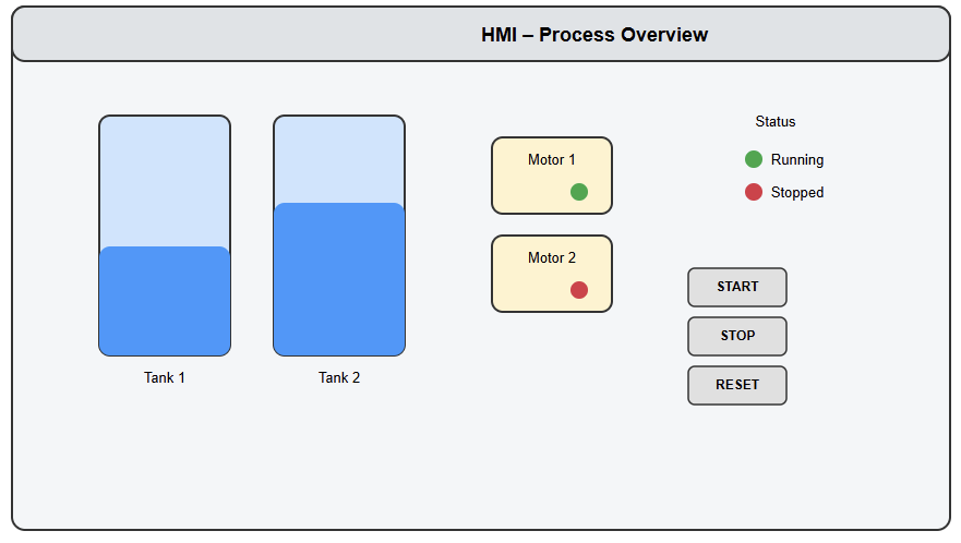
A Human–Machine Interface (HMI) is a user interface that allows operators to interact directly with machines or processes.

Its primary purpose is visualization. It also enables local control. An HMI typically displays real-time data in graphical form. 

This data includes temperature, pressure, motor status, alarms, and production counts. The presentation is designed to be easy to understand. HMIs are often deployed on touch panels or industrial PCs. 

They may also run on embedded displays located near the equipment. A large number of components can be used by operators on the HMI screen.

These could be input fields, sliders, and buttons. These controls allow them to start or stop motors. 

As usual, they also have the ability to adjust setpoints and acknowledge alarms. The HMI communicates directly with one or more PLCs.

This communication uses industrial protocols. Essentially, an HMI provides a visual gateway into a machine or process.

It translates complex control signals into intuitive graphics for human operators.

Characteristics of HMI Systems

HMI systems are typically focused on a single machine or a small section of a plant. Their scope is local rather than plant-wide. They operate in real time. They are also tightly coupled to the PLCs they communicate with. 

Most HMIs store little or no historical data. Instead, they rely on live process values. Another defining characteristic of HMIs is simplicity.

Their configuration is generally straightforward. This makes them suitable for machine-level applications. 

Typical examples include packaging machines, conveyor systems, and standalone production cells. Because of their limited scope, HMIs are cost-effective. They are also easy to maintain.

What Is SCADA?

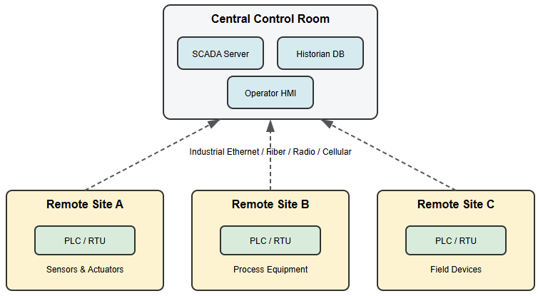
Supervisory Control and Data Acquisition (SCADA) is a computer-based system that allows industries to monitor, control, and analyze real-time data from equipment and processes. It is a comprehensive system designed for large-scale industrial processes. These processes are often spread across wide geographical areas. 

A SCADA system provides centralized oversight, while an HMI deals with local interaction. The SCADA systems can monitor multiple machines, production lines, or entire facilities. SCADA systems collect data from many PLCs and RTUs. 

They also interface with intelligent field devices. The collected data is stored and processed. It is then presented to operators, engineers, and managers. This presentation takes the form of graphical displays, reports, and dashboards. 

SCADA systems also support supervisory control. Operators can issue high-level commands rather than direct machine-level actions. SCADA is commonly used in power generation and water treatment. 

It is also widely applied in oil and gas pipelines and large manufacturing plants. The figure below indicates SCADA system architecture, showing multiple remote sites connected to a central control room.

Core Functions of SCADA Systems

One of the most important functions of SCADA is data acquisition. SCADA systems continuously collect large volumes of data.

This data comes from distributed sources. It is made available in real time. The data is typically stored in historical databases.

These databases support analysis, trending, and reporting. Another key function is alarm management. SCADA systems handle complex alarm logic. They support prioritization and logging. 

This enables operators to respond effectively to abnormal conditions. Advanced SCADA platforms also include event logging and audit trails.

Redundancy features are often implemented. These capabilities improve reliability and regulatory compliance.

SCADA systems also support remote access. Authorized users can monitor and control processes from centralized control rooms. Access is also possible from remote locations.

Interoperability via PLCs and IIoT

Now, industrial automation is in the era of Industrial 4.0 and IIoT. At this point, HMIs and SCADA systems work together through PLCs and other means.

The PLC serves as a bridge between layers. Data is fetched from the PLC by the HMI and is used for immediate operator adjustments. 

At the same time, the SCADA system collects the same data. This data is used to generate system-wide reports. Modern systems increasingly integrate with Industrial Internet of Things (IIoT) platforms. 

Edge HMIs process data locally. This reduces latency. Only critical insights are forwarded to Cloud-based SCADA systems. These platforms enable enterprise-wide analysis.

Architectural Differences

The architectural distinction between HMI and SCADA lies mainly in scale and complexity. An HMI usually connects directly to a single PLC. It may also connect to a small group of controllers. 

Its architecture is simple, and as usual, in many cases, it operates as a standalone system. A SCADA system has a multi-layered architecture.

It includes data servers and communication servers. Historian databases and application servers are also present. 

Client workstations provide user access. Scalability and redundancy are strong prong properties of SCADA architectures. Even if a part of the system fails, this can be ensured by the high availability.

Data Handling and Historian Capabilities

HMIs are designed primarily for real-time visualization. They do not store extensive historical data. Some HMIs retain short-term trends or logs. These are used mainly for diagnostics. 

Long-term data analysis is outside the typical scope of an HMI. SCADA systems are built around robust data historians. These historians store processed data for months or years. 

This enables trend analysis and performance optimization. Predictive maintenance is also supported. Regulatory reporting is another key function. Some technicians and engineers take SCAD for granted. 

But once they deeply dive into it and get some experience, they get to know. For instance, the ability to transform raw data into actionable insights is one of the major advantages of SCADA systems.

User Access and Security

Security requirements differ significantly between HMI and SCADA systems. HMIs usually support basic user authentication. Common roles include operator and maintenance access levels. 

Because HMIs are often local, security risks are relatively limited. SCADA systems require advanced cybersecurity measures.

This is due to their centralized nature and remote connectivity. Role-based access control is commonly implemented.

Encryption and secure communication protocols are essential. This is, for example, when it comes to the current world of Industry 4.0 environments. It should be taken into account that audit trails help ensure accountability. 

Also, it takes into account regulatory compliance. Then, once these measures are taken help protect critical infrastructure from cyber threats.

Scalability and Integration

HMIs are generally not designed to scale beyond their initial application. Expanding an HMI to cover multiple production areas can be challenging. Such expansion often increases complexity. Maintenance effort also grows.

SCADA systems are inherently scalable. They can integrate hundreds or thousands of devices.

Multiple communication protocols are supported. SCADA systems also interface with higher-level platforms. These include Manufacturing Execution Systems, named MES

Typical Applications

HMIs are commonly used in machine-level and cell-level applications. Examples include CNC machines and bottling lines.

Elevators and pump control panels also rely on HMIs. Their primary role is to provide direct control. 

They also deliver immediate feedback to operators. SCADA systems are used when centralized monitoring is required.

They are essential for large-scale data analysis. Power grids and oil pipelines rely heavily on SCADA. 

Water distribution networks and large manufacturing plants also depend on these systems. SCADA ensures coordinated operation and system-wide visibility.

Summary of Key Differences

We all agree that both HMI and SCADA provide visualization and control. We should also agree that their differences are significant.

An HMI is a localized interface. It focuses on direct interaction with machines. SCADA is a supervisory system. 

It is designed for large-scale monitoring and data management. Coordination is supported across multiple locations. A respective study must be done before making a choice. 

Once the study is clear, then the choice between HMI and SCADA creates no complexity. Data requirements and long-term operational goals must also be considered.

Key Takeaways: Difference Between SCADA and HMI

This article addressed the difference between SCADA and HMI by examining their roles and architectures.

Their applications within industrial automation systems were also discussed. Both technologies enable operators to visualize and interact with processes. 

Summing field devices and PLCs, then an HMI is best suited for local, machine-level control. SCADA provides centralized supervision and data acquisition. It also supports long-term analysis for large and distributed systems. 

Understanding these distinctions helps engineers select appropriate solutions. It also supports performance optimization and future scalability.

FAQ: Difference Between SCADA and HMI

What is the main difference between SCADA and HMI?

HMI is a local operator interface, while SCADA is a centralized supervisory system.

Is HMI part of SCADA?

Yes, an HMI can be a component of a SCADA system.

Can an HMI work without SCADA?

Yes, an HMI can operate independently with a PLC.

What is the primary purpose of an HMI?

To visualize and control a machine or process locally.

What is the primary purpose of SCADA?

To monitor, supervise, and manage large or distributed systems.

Does SCADA store historical data?

Yes, SCADA systems use historians to store long-term data.

Do HMIs store historical data?

Usually no, or only short-term trends.

Which system is more complex?

SCADA is more complex than HMI.

Transducer vs Sensor: What are the Differences?

In modern engineering and industrial systems, detecting and measuring physical quantities is essential. These quantities must also be converted into usable signals.

Applications range from temperature control in furnaces to pressure monitoring in pipelines. 

Motion detection in robotics is another common example. Devices known as sensors and transducers perform these tasks. In the area of measurement and control systems, they play a critical role. 

Notice that these terminologies are not identical even if they are often used interchangeably.

This confusion can cause errors in system design and instrumentation selection. This article explains the concepts of sensors and transducers. 

It describes their operating principles. It also clearly outlines the differences between them using practical examples and suggested diagrams.

Understanding Measurement Systems

Every measurement system follows a logical sequence. A physical quantity is a measurable property found in the real world.

Examples include temperature, pressure, displacement, and light. This quantity cannot be processed directly by control systems or computers.

The quantity must first be detected. It must then be converted into an interpretable form. This form allows transmission, processing, or analysis.

This conversion process is central to instrumentation engineering. Several devices may be involved. 

Some detect physical phenomena. Others convert energy, condition signals, or transmit information.

Sensors and transducers operate within this chain. Their roles are distinct and hierarchical.

The following figure indicates a block diagram showing physical quantity, sensor, signal conditioning, and output.

What is a sensor?

A sensor is often defined as a device that receives and responds to a signal or stimulus.

The stimulus is the quantity, property, or condition that is sensed and converted into an electrical signal.

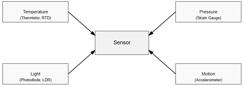
It might be temperature, pressure, force, light, humidity, gas concentration, or motion. The primary role of a sensor is detection.

A sensor does not necessarily provide a standardized electrical output. In many cases, it produces a change in a physical property.

For example, an RTD changes resistance as temperature varies. A thermistor behaves similarly but with nonlinear characteristics.

These devices sense temperature effectively. However, their outputs are not directly usable by control systems.

Sensors are therefore considered the first element in a measurement chain. They are in direct contact with the process or environment.

Careful selection is of key importance. Durability, repeatability, and accuracy must match operating conditions. The next figure shows an illustration of different physical quantities interacting with sensors.

Characteristics of Sensors

Sensors are defined by several performance parameters. These include sensitivity, range, accuracy, resolution, and response time.

Sensitivity describes output change relative to input change. Range defines the limits of reliable detection.

Environmental robustness is also critical. Take into account that industrial sensors may face vibration and moisture.

In addition, face corrosive chemicals and/or extreme temperatures. For this reason, adequate protective housings or coatings are often required.

A sensor alone may not produce a usable signal. Additional circuitry is often needed. This circuitry converts, amplifies, or standardizes the output.

What Is the Meaning of a Transducer?

A transducer converts energy (variation) from one form to another. In the world of instrumentation, this usually means converting a physical quantity into an electrical signal.

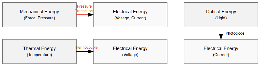
This physical quantity could be pressure or brightness. A thermocouple is one of the most well-known examples. Hence, conversion is the defining function. 

A pressure transducer is used to convert mechanical pressure into two formats. These formats could be voltage form or current form.

For instance, a microphone converts sound into an electrical signal. While a loudspeaker performs the reverse conversion.

In many systems, a transducer contains a sensor. It also includes components for signal conversion. The result is a usable and standardized output.

Types of Transducers

Transducers are commonly classified as input or output devices. Input transducers convert physical quantities into electrical signals. Examples include pressure accelerometers, thermocouples, and transducers.

Output transducers perform the opposite function. General actuators, solenoids, and motors convert electrical signals into physical action.

Transducers may also be active or passive. Active transducers generate output without external power. 

Thermocouples are a typical example. Passive transducers require excitation. Strain gauges and RTDs fall into this category. This classification differs from sensors.

Sensors are grouped based on the quantities they detect rather than their energy conversion method.

Sensors and Transducers: Relationship

The relationship is best explained hierarchically. A sensor is often part of a transducer. The sensor detects the physical quantity. The transducer ensures usable energy conversion.

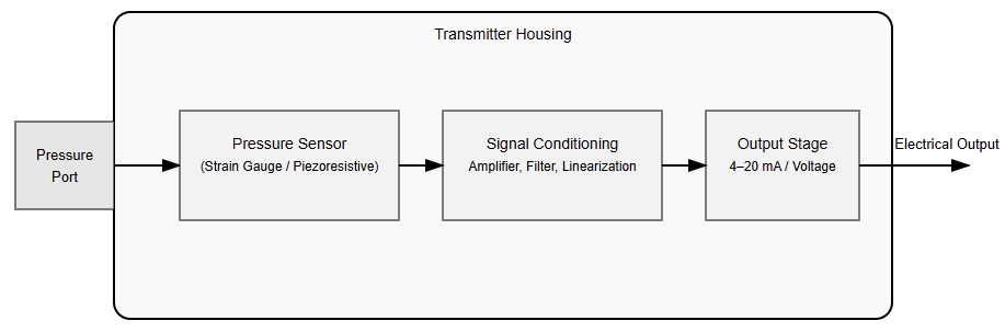
Consider an industrial pressure transmitter. A sensing element detects pressure-induced deformation. This sensing element changes resistance. On its own, it is only a sensor.

The transducer circuitry converts this change. It produces a standardized 4–20 mA signal. This signal can be transmitted reliably over long distances. All transducers contain sensors. Not all sensors are complete transducers.

Sensor and Transducer: Key Differences

The important difference is based in functionality of each one. A sensor detects a physical quantity.

A transducer converts energy. Detection indicates the presence of change. Conversion produces a usable output. Sensor outputs may be resistance or displacement changes. 

Transducer outputs are typically voltage, current, or frequency. From a system perspective, sensors interface with the process.

Transducers interface with control systems. This distinction is important in specifications and procurement.

Examples Illustrating the Difference

A bimetallic strip bends whenever there is a change on temperature change. It senses temperature, but it does not generate an electrical signal. It functions as a sensor.

The system turns into a transducer when the aforementioned motion is converted into an electrical signal.

A light-dependent resistor changes resistance with light intensity. It is a sensor. When paired with a circuit that outputs voltage, it becomes a light transducer.

In industry, datasheets often reflect this distinction. The sensing element is called a sensor. The complete device is called a transducer or transmitter.

Applications in Engineering and Industry

Sensors and transducers are used across many fields. These include robotics, automotive systems, and most importantly, automation. In addition, they are also useful in medical equipment and electronics. 

In control systems, accurate sensing ensures stability. Reliable transduction ensures compatibility with controllers.

In process industries, transmitters enable remote monitoring. In robotics, sensors detect position and force. 

Transducers convert these detections into electrical signals. This enables real-time control. Understanding the distinction improves device selection.

Common Misunderstanding

A large number of technicians and/or engineers have a common misconception. This is to think that sensors and transducers are identical. This is not true. Every transducer includes sensing, but not every sensor performs transduction.

Another misunderstanding is assuming sensors always produce electrical outputs. Many do not.

Loose terminology contributes to confusion. One of the essential requisites in engineering communication is precise language.

A Sensor and a Transducer?

The choice depends on application needs. Simple detection may only require a sensor. System integration usually requires a transducer.

Engineers must consider signal compatibility and the environment. Accuracy and cost are also factors. Complete transducers often reduce complexity and improve reliability.

Key Takeaways: Transducer vs Sensor

This article addressed the fundamental differences between sensors and transducers. It clarified how both are used in measurement systems. A sensor is responsible for detecting physical quantities. 

These quantities include temperature, pressure, light, or motion. A transducer performs energy conversion.

It produces a usable output signal, most often electrical. Although the terms are often used interchangeably, they represent different functions. 

Sensors are closest to the physical process. Transducers interface directly with control and monitoring systems.

Understanding this distinction improves device selection. It also reduces design errors and specification ambiguity. 

Clear terminology supports reliable system design. It ultimately leads to better performance in industrial and engineering applications.

FAQ: Transducer vs Sensor

What is a sensor?

A sensor detects a physical quantity and responds to changes in the environment.

What is a transducer?

A transducer converts one form of energy into another, usually into an electrical signal.

Are sensors and transducers the same?

No. A sensor detects, while a transducer converts energy into a usable output.

Does a transducer contain a sensor?

Yes, most measurement transducers include a sensor as the sensing element.

Can a sensor work without being a transducer?

Yes. Some sensors only change a physical property and do not provide a usable output.

Does a sensor always produce an electrical signal?

No. Some sensors produce resistance, capacitance, or mechanical changes.

What kind of output does a transducer provide?

Typically, a usable electrical signal is a voltage, current, or frequency.

Is every sensor a transducer?

Not necessarily. Only sensors that perform energy conversion qualify as transducers.

Why is the difference important?

It helps in proper device selection and clear engineering communication.

Can a transducer work in reverse?

Yes. Some transducers act as actuators, converting electrical energy into physical output.

Differential Pressure Transmitters

Differential Pressure Transmitters, also known as DP transmitters, are among the most widely used instruments in industrial measurement and control systems.

They play a critical role in monitoring flow, level, pressure, and filter condition across numerous industries. 

These industries include power generation, water treatment, and oil and gas. In addition, pharmaceuticals and manufacturing are also incorporated.

By measuring the difference between two pressure points, differential pressure transmitters provide indirect measurements.

These measurements are highly reliable and represent key process variables. Their robustness and accuracy make them essential components in modern automation systems. Also, their versatility is characteristic.

Understanding their operating principles and construction is vital for engineers. Understanding their applications and limitations is also essential.

This article addresses operating principles and construction in detail. It also covers measurement methods, applications, selection criteria, and practical considerations.

DP Transmitter

A differential pressure transmitter is an instrument that measures pressure difference. This difference exists between the two applied pressures. The pressures are applied to high-pressure and low-pressure ports. 

Instead of measuring absolute pressure at one point, the transmitter compares two values. It then outputs a standardized signal. This signal is proportional to the measured difference.

The output signal is standardized for industrial control systems. Most transmitters provide a 4–20 mA analog current signal. Some models instead provide a 0–10 V analog voltage output. 

Modern smart transmitters also support digital communication protocols. PROFIBUS, Modbus, Foundation Fieldbus, and HART are examples of these protocols. The measured differential pressure is often used indirectly. It is used to infer the flow rate. 

It is also used to determine the liquid level. Filter condition can also be monitored this way. This versatility makes differential pressure transmitters widely applied instruments.

Basic Operating Principle

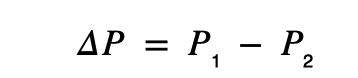
The operating principle of a differential pressure transmitter is based on pressure comparison. It measures the pressure difference between two points. This difference is expressed as

P₁ represents pressure at the high-pressure side. P₂ represents pressure at the low-pressure side. This pressure difference causes mechanical deformation.

The deformation occurs in the sensing element. The amount of deformation depends on the pressure magnitude. 

This mechanical movement is converted into an electrical signal. The signal is amplified and conditioned.

It is then transmitted to the control system. This principle is widely applied in industrial processes.

In flow measurement, pressure is measured before and after a restriction. In level measurement, vessel pressures are compared vertically.

In filter monitoring, pressure is measured upstream and downstream. These comparisons allow detection of clogging or process changes.

Main Components

A typical differential pressure transmitter consists of several essential components. These components work together to ensure accurate measurement.

The pressure ports provide physical process connections. One port is assigned as high-pressure. 

The other port is assigned as low-pressure. The difference between these pressures is measured.

The sensing element reacts mechanically to differential pressure. Common sensing elements include diaphragms and bellows.

Flexible membranes are also widely used. The element deflects proportionally once pressure is applied.

Mechanical deformation is converted into an electrical signal by the sensor. This conversion depends on transmitter design. 

Technologies include strain gauges and capacitive sensors. Piezoresistive and resonant sensors are also used.

The signal conditioning circuit processes the raw sensor signal. It amplifies low-level signals. It also linearizes the output. 

Temperature compensation is applied to improve accuracy. The output and communication interface deliver the processed signal. This signal is sent to external systems. Outputs may be analog, digital, or combined.

Types of DP Transmitters

Differential pressure transmitters are categorized by sensing technology. They are also categorized by intended application.

Diaphragm-based transmitters use flexible diaphragms. These diaphragms deflect under a pressure difference. 

They offer high accuracy and excellent stability. They are suitable for low to medium pressure ranges.

Capacitive differential pressure transmitters detect capacitance changes. These changes occur due to diaphragm movement. 

They are well-suited for very low pressures. High sensitivity makes them ideal for cleanrooms and low-flow applications.

Piezoresistive transmitters use strain-sensitive resistors. These resistors are bonded to a diaphragm. 

Pressure-induced deformation changes electrical resistance. These transmitters are common in medium to high-pressure applications. Resonant sensor transmitters measure vibration frequency changes. 

These changes result from pressure-induced stress. They offer exceptional accuracy and long-term stability. However, they are generally more expensive.

Differential Pressure Measurement Methods

Differential pressure transmitters are widely used for indirect measurement. They rely on established physical relationships. These relationships link pressure difference to other variables.

Flow Measurement Using Differential Pressure

Flow measurement is a common application of differential pressure transmitters. A restriction is placed in the flow path. This restriction causes a pressure drop. The pressure drop is related to the flow rate. 

The transmitter measures this differential pressure. Common primary flow elements include orifice plates.

Venturi tubes and flow nozzles are also used. Pitot tubes are applied in some cases. Here, the mathematical equation is based on the relationship between flow and pressure.

This is how they relate: Flow rate is proportional to the square root of differential pressure. Accurate calibration is therefore essential.

Level Measurement Using Differential Pressure

Liquid level measurement using differential pressure is widely applied. It is used in both open and closed tanks.

The pressure exerted by a liquid column depends on height. It also depends on liquid density. 

In open tanks, the high-pressure side connects to the bottom. The low-pressure side is vented to the atmosphere.

In closed tanks, the low-pressure side connects to the vapor space. In both cases, the measured differential pressure corresponds to the liquid level.

Filter and Pump Monitoring

Differential pressure transmitters are commonly used for equipment monitoring. Filters, pumps, and heat exchangers are typical examples. As a filter becomes clogged, the pressure drop increases. 

Continuous monitoring reveals this change. Abnormal pressure differentials can indicate problems.

These problems include cavitation and fouling. Mechanical issues can also be detected early.

Installation Considerations

Correct installation is essential for accurate measurement. Poor installation can introduce significant errors.

Pressure tapping points must be carefully selected. Technicians must make sure they avoid areas of turbulence. 

Air entrapment and sediment buildup must also be prevented. In flow measurement, standardized tapping locations are often used.

Impulse lines should be equal in length. They must be properly sloped. This prevents trapped gas or liquid columns. 

Such conditions can cause measurement errors. Mounting position can affect the zero offset.

Hydrostatic head may influence readings. Zero calibration is often performed after installation. 

This compensates for mounting effects. Environmental conditions must also be considered. These include temperature extremes and vibration. Moisture and affect reliability.

Maintenance and Calibration 

Calibration ensures measurement accuracy across the operating range. Known differential pressures are applied during calibration. Zero, span, and linearity are adjusted accordingly. 

Calibration is commonly performed using pressure calibrators. Deadweight testers are also used.

Smart transmitters support digital calibration. Verification can be done without removing the device. 

Routine maintenance includes impulse line inspection. Blockage and leakage must be checked. Seals and diaphragms are inspected regularly.

Output signals should be verified. Due to devices’ connectivity capability, remote diagnostics are now possible. The main advantage of these is the reduction of downtime and costs.

Advantages and Disadvantages

The DP transmitters offer a vast range of advantages, such as high accuracy and repeatability.

They are suitable for critical process measurements. Their versatility allows use across multiple applications. Flow, level, and pressure monitoring are all possible.

The technology is well established and standardized. It is compatible with PLC and DCS systems.

These transmitters operate reliably in harsh environments. However, certain limitations exist. 

Measurements are often indirect. Accuracy depends on fluid density and temperature. Impulse lines may clog, freeze, or leak. Flow accuracy decreases at low rates. Proper design and maintenance are essential.

Applications Across Industries

Differential pressure transmitters are used in many industries.

  • Oil and gas: they measure flow and separator levels. They are also used for pipeline monitoring. 
  • Power plants: They measure steam flow. They also control the boiler drum level. 
  • Water and wastewater systems: They monitor filters and are used for flow measurement. 
  • Pharmaceuticals: They control cleanroom pressure. They also support sterile processes. 
  • HVAC systems: They measure airflow. They also balance room pressure.

Selection Criteria

When specifying a transmitter, several factors must be considered. Material compatibility is critical. Wetted parts must suit the process medium.

Although 316L stainless steel is the industry benchmark, extreme corrosive applications may mandate the integration of Tantalum, Monel, or Hastelloy.

Turn-down ratio is another important factor. It defines the usable measurement range. Accuracy must be maintained across this range. Modern transmitters achieve turndowns up to 100:1.

Digital communication is increasingly important. Protocols such as HART 7 and Modbus are common.

WirelessHART supports predictive maintenance and integration. Multivariable transmitters provide additional benefits. 

They measure differential pressure and static pressure. They also measure process temperature.

This enables compensated mass flow measurement. Instrumentation complexity is reduced.

Key Takeaways: Differential Pressure Transmitters

This article details the fundamentals of differential pressure transmitters. It covered operating principles and key components. Measurement methods and installation practices were explained. 

Advantages, limitations, and applications were discussed. Differential pressure transmitters remain fundamental instruments. They support industrial measurement and control systems. 

By measuring pressure difference, they determine flow and leve