How to Wire a 2-Way Light Switch

2-way switching provides convenience and safety in homes. Consequently, wiring a two-way light switch is a common task in homes. This is frequent in spaces where convenience and safety matter.

A 2-way setup allows the user to control a single light from two different points.  Most of these points are upstairs and downstairs. This setup is ideal for hallways, staircases, and rooms that have more than one entry door. 

The concept may look confusing at first, but once you understand how the switch terminals work and how the travelers connect, the process becomes far easier to follow.

This article explains the wiring of a 2-way light switch. It makes clear what it is, how it works, and its applications.

What a 2-Way Light Switch Does

A 2-way switch changes the path of the electrical live conductor so that either switch can complete or break the circuit feeding the lamp.

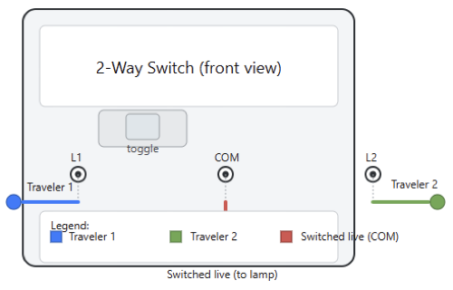
Each switch has a terminal labeled “COM” (common) and two terminals usually labeled “L1” and “L2,” which act as traveler points. 

When you flip the switch, it shifts the live feed from COM to either L1 or L2, and the second switch repeats this process.

Together, both switches determine whether the lamp connects to power. This explains why the light can be turned on from point A and then turned off from point B.

How to Wire a 2-Way Light Switch

Where 2-Way Switching Is Typically Used

You will find 2-way switching in many areas of a home where people need to control a light from different positions.

A common significant example of 2-way switching is in hallways, which typically have entry points at both ends. 

In addition to hallways, staircases benefit from this setup. This arrangement allows a user to turn the light on at the bottom (downstairs). They can then turn it off at the top (upstairs).

Some large living rooms, garages, and bedrooms use 2-way switching. This is for added convenience.

This arrangement prevents situations where you are forced to cross a dark room just to reach a switch. It improves safety.

Basic Operating Logic

The logic behind 2-way switches is straightforward, even if their operation may appear complicated.

The aim of each of the two switches is to direct the live feed through one of two traveler wires. 

The position of switch A must match the position of switch B for the circuit to complete. Once this condition is met, the lamp turns ON.

This means they both routed the live feed through the same traveler. If the two switches route power through different travelers, the circuit breaks, and the lamp remains off.

The clever part is that either switch can change the state of the light, regardless of the other switch’s current position.

Safety Steps Before Starting the Wiring Work

As mentioned above, electricity is dangerous, and we have to take several measures before handling any electrical wiring. So, here some few steps briefly explained

  • First, switch off the power at the main breaker. 
  • Verify if the circuit is dead using a voltage tester. It is not safe to rely on a switch alone. 
  • Wearing insulated gloves is a good option. Also, ensure that you work in a dry environmental condition.
  • Tools must be kept organized, and avoid leaving bare copper exposed longer than necessary. 
  • If observing discolored and brittle wiring, stop the installation immediately and call a licensed electrician/technician. This is also applied to the old wiring.

When dealing with electrical work and installations, safety must always be the first priority.

One of these safety measures is to turn off the power to the main breaker panel. Notice that this must be done before handling any electrical wiring activity. Then, it must be preceded by verifying if the circuit is dead using a voltage tester.

Tools Required for Wiring a 2-Way Switch

To complete the installation, you need electrical tape, a voltage tester, wire strippers, and a screwdriver set. Pliers can help you bend or shape conductors before inserting them into terminals.

A multimeter is not that much required, but it can make troubleshooting much easier. This is especially true when the circuit does not function correctly on the first attempt. Qualified personnel should make sure all of the tools have insulated handles and are in good condition before beginning to work with them.

Materials for the Installation

The needed materials during installation are double 2-way switches of type single-pole double-throw.

You will need a length of suitable three-core or four-core cable, depending on local wiring requirements, as well as a junction box. 

The junction box is necessary only if the wiring layout requires one. Also, a ceiling rose or light fixture and proper connectors.

Ensure that all materials meet local electrical standards. Uncertified materials must be avoided because they can cause premature failure, overheating, or loose connections.

Understanding Switch Terminals: COM, L1, and L2

Every 2-way switch has a COM terminal that either receives or sends the live feed. When you flip the switch, COM connects to either L1 or L2.

These L1 and L2 terminals form the traveler pair that runs between the two switches. The direction of the current through these travelers determines whether the lamp sees a complete circuit.

Misplacing the COM wire is the most common mistake people make when wiring a 2-way switch, so always check terminal labels carefully.

Two Common Wiring Methods

The traditional 3-wire method and loop-in method are the two standard methods used for wiring a 2-way light switch. Both achieve the same result, but the cable routing differs. 

The traditional method sends both travelers and the common wire directly between the two switches, while the loop-in technique keeps neutrals and permanent lives at the ceiling rose and sends only the switching wires to the switches. Both are widely used, and the choice depends mostly on the house’s wiring layout.

How the Traditional 3-Wire Method Works

In the traditional 3-wire method, live power enters the first switch at the COM terminal. Two traveler wires run between the two switches.

This leads to the connection of L1 to L1 and L2 to L2. The second switch uses its COM terminal to send switched live to the lamp. 

The lamp’s neutral bypasses the switches and goes directly to the lighting circuit’s neutral point. This method is simple to trace, making it popular for older or simpler installations.

Wiring the Traditional 3-Wire Method

As stated above, one should start by turning off the power before starting to wire the system.

Mount both switches and run a three-core cable between them. Strip the wires and insert the live feed into COM on switch one. Connect the first traveler to L1 on both switches.

 Connect the second traveler to L2 on both switches. Then run a wire from the COM on switch two to the lamp’s live terminal.

Ensure the neutral from the lamp connects directly to the supply neutral. All terminal screws must be tightened carefully, and finally, power to test the system 

The Loop-In Method

This is a common electrical wiring technique for lighting circuits where cables are “looped in” at each connection point.

This connection point could be a ceiling rose or a light switch, which helps create a continuous circuit. 

Instead of using a separate junction box for every connection, the live (line), neutral, and earth wires are connected directly to the terminals and then continue to the next point in the circuit.

The loop-in method places all neutrals and permanent lives inside the ceiling rose instead of inside switch boxes. 

Only the necessary switching wires run down to the wall switches. This keeps the wiring almost perfectly organized and reduces the number of junction boxes. 

Many electricians prefer this method in modern homes because it simplifies troubleshooting. Plus, it reduces the number of connections inside the switch boxes.

Steps for Wiring the Loop-In Method

Turn off the power and open the ceiling riser. Identify the permanent live feed, the neutral group, and the switched live terminal. Connect the permanent live to COM on switch one. 

Run two traveler wires between the L1 and L2 terminals of both switches. Then connect the COM of switch two back to the switched live terminal on the ceiling rose.

Keep all neutral wires grouped in the rose. After tightening all connections, test the circuit with power restored.

How Power Flows Through the Circuit

The live conductor enters switch 1 and gets routed through one of the two travelers. Switch 2 receives this traveler signal and may either pass it to the lamp or switch it to the other traveler, depending on its position. 

When the outgoing conductor from switch two delivers power to the lamp, the circuit completes, and the light turns on.

If the switches route power through different travelers, the circuit breaks, and the lamp stays off.

Testing the Installation

When the wiring is done, it should be double-checked. If everything is OK, then turn on the breaker and try operating the light from both switches. The COM connection is nearly always the problem if neither switch is able to toggle the lamp.

The light may develop the flicking behavior; the issue can be solved by checking for loose screws or damaged conductors.

As a tradition of electrical engineers/technicians, testing the system before closing the switches is a must.  This makes sure that any issues can be corrected quickly.

Common Wiring Mistakes and Fixes

The most frequent mistake is mixing up the COM terminal with L1 or L2. Another common error is reversing the traveler wires.

This kind usually causes erratic operation. Always loose terminals tend to cause flickering, heating, or intermittent failures. 

If nothing works, the steps mentioned above must be followed. This means turn off the power and inspect each connection.

A continuity tester helps verify which wire goes where. Taking your time during this step avoids hours of frustration later.

Using a Junction Box

If cables cannot reach the switches directly, the use of a junction box becomes necessary. It should be large enough to hold all conductors comfortably. In addition, it must remain accessible according to the electrical code. 

Proper connectors must be used inside the box; cables with clamps must be used; and the lid must be firmly closed. Never bury a junction box behind a wall or ceiling without access.

Intermediate Switch

The so-called intermediate switch can be added to control the same light from three or more locations. This is added between the two 2-switches.

This intermediate switch has four terminals and simply swaps or crosses the two traveler wires depending on its position. 

You can insert multiple intermediate switches in long hallways or large rooms for additional control points.

Choosing the Right Switch Type

Plastic or metal switch plates can be chosen. Plastic switches are inexpensive and easy to install.

These usually do not require grounding. On the contrary, metal switches look more premium but must be earthed properly. 

Local electrical regulations and aesthetics are also to be considered. No doubt, the check must be done to verify that the switches are rated for the correct voltage and current.

Clean and Reliable Wiring

There is no doubt that neat wiring reduces the chance of future problems. Excessive slack may cause a serious problem.

So, trim wires to the proper length so they fit comfortably without excessive slack. Keep travelers bundled neatly to avoid confusion. 

The terminal screws must not be overtightened; instead, ensure they are firm. Leave enough room inside the box for heat dissipation and inspection. Clear labeling helps a lot if anyone needs to service the switches later.

Troubleshooting After Installation

The light must not remain on permanently. If this happens, check the travelers for a possible cross-connection.

If the light never comes on, carefully verify that the live feed is actually reaching the first COM terminal.

Most of the time, a buzzing sound from the switch means arcing. This may be caused by a large number of reasons, one of which is a loose connection. Systematically testing each part of the circuit helps isolate the problem quickly.

Modern Alternatives to Traditional 2-Way Switching

In the near future, smart switching systems can replace traditional 2-way wiring. Smart switching systems enable users to control lights through Wi-Fi, apps, or voice assistants. Some smart switches can work in a 2-way configuration, while others require rewiring. 

Many require a neutral conductor at the switch box, which older installations may not provide.

Although they offer convenience and features, they are pricier and sometimes harder to integrate into existing wiring.

Conclusion

This article explained how a two-way light switching system works. It also detailed how to mount it, where it can be used, the safety precautions to be considered during the manipulation, and how to wire it safely. 

Once the functionality of the COM and traveler terminals is clear, wiring a 2-wire light becomes easy.

The system allows two switches to control one lamp by routing power through two possible paths. 

These are mostly staircases (downstairs and upstairs). This installation should be completed using the appropriate materials and tools.

Also, attention to safety should be considered. If these requirements are followed, anyone with basic electrical knowledge can complete the installation.  

The key is understanding the wiring method you are using and following it carefully. Qualified personnel are free to choose between the traditional 3-wire system or the loop-in method. 

Once you study and follow the diagrams patiently, the process becomes clear. A well-wired 2-way switch increases convenience, safety, and reliability in any home.

FAQ: How to Wire a 2-Way Light Switch

What is a 2-way light switch?

It’s a setup that lets you control one light from two different switches.

What terminals do 2-way switches have?

They normally have COM, L1, and L2.

What cable do I need?

Use a 3-core + earth cable between both switches.

Which wire goes to COM?

On the first switch, the live feed goes to COM. The switch line goes to COM on the second.

What are L1 and L2 for?

They are the traveler wires that link both switches.

Do the travelers cross?

Yes. L1 connects to L1, and L2 connects to L2.

Do I need to turn off the power?

Yes. Always isolate the circuit before touching any wiring.

Can I use any 2-way switch brand?

Yes, as long as it’s labeled COM, L1, and L2.

Why does my 2-way switch not work?

Most failures come from the COM being wired incorrectly.

Are diagrams necessary?

Yes. Follow a wiring diagram to avoid mistakes.

Can a 2-way circuit be used with LEDs?

Yes. It works the same as with standard bulbs.

What if my walls only have two wires?

Then it’s likely a 1-way setup, and rewiring is needed for 2-way control.

Do both switches need COM in the same position?

No. COM positions vary by brand. Always check the label.

What is a Star-Delta Starter and How Does it Work?

A star-delta starter, also known as a Wye-Delta starter, is a popular way of reduced-voltage motor starter.

It is especially helpful when the objective is to reduce the high inrush current. This current appears during direct-on-line starting. 

Instead of applying full line voltage immediately, the motor begins in a star connection. This lowers the voltage across each winding, and it limits the current. After the motor reaches a certain speed, the connection shifts to delta. 

This allows the motor to run at its full rated power. The technique is reliable, cost-effective, and simple.

It is also widely used in many industrial applications. This article studies what a star-delta starter is, why it is used, and how it works in real industrial settings.

The Basic Idea

The star-delta starter is built around one main idea. The goal is to start a motor at reduced voltage to limit the mechanical and electrical stress that naturally occurs during startup. 

When a motor starts, the rotor is stationary, and this causes the stator to experience very low impedance.

This results in extremely high starting current. By beginning in a star connection, each winding receives a lower phase voltage. 

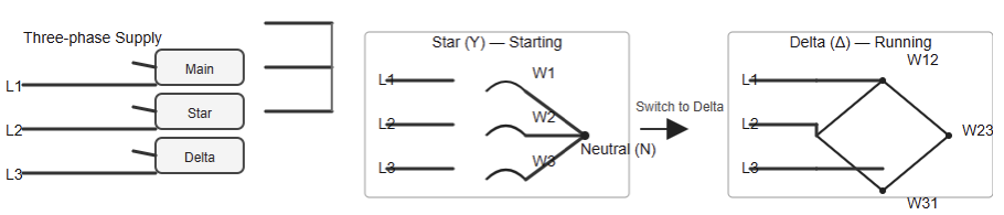
This keeps the current under control. It still provides enough torque to begin acceleration. The following figure shows a simplified schematic illustrating star and delta connections.

The Need for Reduced-Voltage Starting

Induction motors can draw six to eight times their rated current during startup. This surge only lasts a few seconds. However, it can cause voltage dips, light flickering, and tripping of protection devices. 

Many electrical networks cannot handle this sudden load comfortably. The issue becomes worse when several machines share the same supply. Reduced-voltage starting methods like star-delta help the motor begin more gently. 

They do this by lowering the current drawn from the grid during the first seconds of operation.

For loads such as fans and pumps, the reduced starting torque is still enough to set the rotor in motion. Similar situation when it comes to blowers.

Star Connection

Another option is a star connection. When a motor is connected in a star, the ends of its three windings are tied together at a single neutral point.

The other ends are connected to the three-phase supply. Because of this configuration, each winding receives line voltage divided by √3. 

This arrangement significantly reduces the applied voltage. Lower voltage results in lower current. It also reduces the torque produced.

However, the motor still produces enough torque for light to medium loads. This is why the star connection is ideal for the initial acceleration phase.

Delta Connection

Once the motor accelerates to around 70–80% of its rated speed, it is ready for full voltage.

It then receives full line voltage through a delta connection. In this mode, each winding is linked between two phases. 

This allows the motor to deliver its rated torque and power. The shift from star to delta is automatic.

It is controlled by the starter’s timing system. Delta is the normal running mode for most industrial motors.

Switching Mechanism 

A star-delta starter uses three contactors. These are the main contractor, the star contactor, and the delta contactor.

When the operator presses START, the main and star contactors close. This connects the motor windings in a star.

A timer begins counting. It allows the motor to accelerate under reduced voltage. After the preset time expires, the star contactor opens. Then the delta contactor closes.

This completes the transition to full voltage. Interlocks ensure the star and delta contactors never engage at the same time. They prevent short circuits and equipment damage.

Sequence of Operation

The operation follows a predictable sequence. First, the main contactor energizes. This supplies power to the motor.

Immediately afterward, the star contactor closes. The motor begins in the star configuration with reduced voltage. 

During this period, the motor gains speed gradually. When the timer finishes its delay, the star contactor drops out.

A short safety pause follows. Thereafter, the delta contactor closes. The motor then runs at full line voltage. 

The switching must be precisely timed. Incorrect timing may produce torque shocks or transition problems.

Components of Star-Delta Starter

A complete starter contains several critical components. The main, star, and delta contactors carry the load and switch the windings. The overload relay protects the motor from excessive running current. 

The timer controls the delay before switching. Interlocks prevent simultaneous engagement.

Additional components, such as control relays and auxiliary contacts, support the control logic.

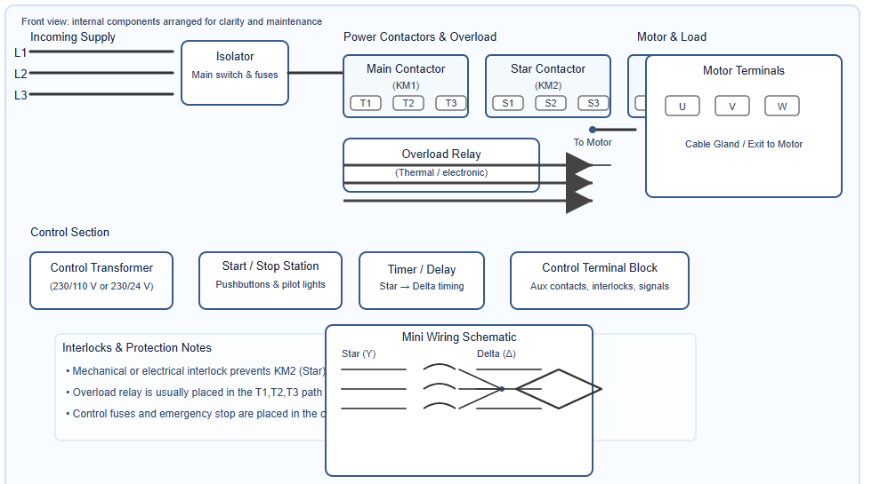
A control transformer may also be included when needed. The following figure indicates a start-delta panel layout.

Why Interlocking Is Essential

Interlocking prevents dangerous overlap between the star and delta contactors. Mechanical interlocking uses a physical mechanism. It blocks one contactor when the other is active. Electrical interlocking uses auxiliary contacts. 

They break or allow coil current depending on the state of the opposite contactor. Without interlocking, both contactors could close at the same time.

The process would create a phase-to-phase short. Such a short could destroy the contactors. It could also damage the motor.

Advantages of Using a Star-Delta Starter

Star-delta starters offer several strong benefits. They significantly lower the starting current. They also reduce mechanical stress on the motor shaft and bearings. Voltage drops in the electrical supply are minimized. 

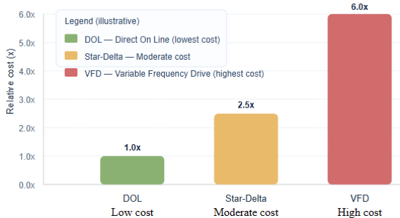
This helps stabilize the grid. The design is simple and inexpensive. It is cheaper than soft starters or VFDs. Maintenance is straightforward because most parts are electromechanical.

The figure below depicts the comparison of DOL, star-delta, and VFD in terms of costs.

Limitations and Downsides

Despite the advantages, the star-delta method has limitations. It provides only one fixed level of voltage reduction. The transition between star and delta is abrupt. This can create torque spikes. 

Reduced starting torque makes the method unsuitable for heavy loads. Motors must also have six accessible terminals. Not all motors are built this way.

The method is not ideal when frequent starts are required. Contactors will wear out faster under those conditions.

Applications of Star-Delta 

Star-delta starters are the best fit for loads that can accelerate easily under reduced torque.

Common examples include fans, centrifugal pumps, blowers, and compressors. Long conveyors with low friction also fit this category. 

These loads do not need high initial torque. The reduced torque in star mode is still enough to start them. For heavy loads such as crushers or hoists, other starting methods are required.

Requirements for Star-Delta Operation

A star-delta starter requires a motor designed for delta operation at the supply voltage. It must also provide access to all six winding terminals.

Motors labeled “400V Delta / 690V Star” are usually a perfect fit for electrical systems running at 400 volts.

A vast number of motors consist of only three terminals. These cannot be switched externally.

Their internal winding configuration cannot be changed. Choosing the correct motor is essential.

The Transition Challenge

One drawback of the star-delta method is the momentary disconnection during switching. This short interruption can cause a current spike. It can also cause a torque dip. Engineers must select the transition delay carefully. 

The motor must reach enough speed in star mode. Poor timing can lead to stress, voltage spikes, or even motor stalling.

Star-Delta vs Soft Starters

Soft starters use solid-state devices to ramp voltage smoothly. They offer controlled acceleration.

They avoid the mechanical and electrical shocks seen in star-delta transitions. Their settings are adjustable. 

However, they cost more. They also require cooling because they generate heat. Star-delta is still attractive for simple and low-cost installations.

Star-Delta vs Variable-Frequency Drives

Variable-Frequency Drives (VFDs) offer the most advanced motor control. They adjust both voltage and frequency.

This method provides full torque even at low speeds. They provide soft start, speed control, protection, and energy savings.

The disadvantages are cost, complexity, and harmonics. Star-delta remains useful where speed control is not required. It is simple, rugged, and economical.

Panel Layout and Wiring Considerations

A star-delta panel is organized to keep components accessible. The main contactor is usually placed in the center.

The star and delta contactors are mounted beside it. The overload relay sits below the main contactor. 

The timer is installed in the control wiring section. Good cable routing and labeling reduce errors. They also speed up maintenance.

Maintenance and Troubleshooting

Star-delta starters need periodic inspection. Contactors should be checked for wear or pitting.

Coils should be tested for proper operation. The timer must be verified to ensure the correct delay. Overload relays should be inspected and reset if necessary. 

When faults occur, technicians often begin by checking the contactor sequence. Incorrect sequencing causes most failures.

Modern Enhancements and Hybrid Designs

Modern star-delta systems may include electronic timing modules. These provide more precise control.

Some designs combine electromechanical and solid-state components. This hybrid approach smooths the transition between star and delta. 

It reduces mechanical wear. It also lowers electrical stress. Some systems include advanced protection and communication features. Such functionality makes them more suitable for modern automation environments.

Conclusion

This article reviewed the principles, components, operation sequence, applications, and limitations of the star-delta starter.

A star-delta starter remains a practical and trusted solution for many industries. It is simple. It is affordable. 

And it is effective in reducing the starting current of three-phase motors. The method uses a star connection during startup.

This practice reduces voltage. It also reduces inrush current. After the motor accelerates, the system changes to delta. 

Then the motor receives full line voltage. This allows the motor to deliver full torque and operate at its rated condition.

The approach works well when loads are light or medium during startup. It is also ideal when budgets are limited. 

However, star-delta starters are not perfect. They create a momentary torque dip during transition.

They also do not offer smooth acceleration like modern electronic starters. Even so, the technique remains popular. Its reliability keeps it relevant.

Its low cost makes it attractive. Its simplicity guarantees its long-term use in numerous systems.

FAQ: What is a Star-Delta Starter, and How Does it Work?

What is a Star-Delta Starter?

A Star-Delta Starter is a reduced-voltage motor starter that starts in star mode and then transitions to delta mode.

Why is it used?

To cut down the high inrush current during motor startup.

How does it work?

The motor starts in star mode, accelerates, and then the timer switches it to delta mode.

What happens in star mode?

The motor receives reduced voltage and torque.

What happens in delta mode?

Motor receives full voltage and runs at rated power.

What are the advantages?

The advantages include a lower starting current, reduced stress, simplicity, and affordability.

What are the disadvantages?

The disadvantages include a low starting torque and a brief torque dip during the transition.

What components does it use?

It utilizes three contactors, a timer, and an overload relay.

When should it be used?

For motors with light or medium startup loads.

When shouldn’t it be used?

It should not be used for heavy loads or high-torque startup applications.

Does every motor support star-delta?

No. Only motors with six accessible terminals.

Is it better than a VFD?

No. VFD gives better control but costs more.

What Is a Circuit Breaker?

A circuit breaker is a small device with a very crucial functionality. It keeps electrical systems safe.

It stops electricity when something dangerous happens. It protects people, buildings, and equipment. It reacts when the current becomes too high. 

It also responds when a short circuit occurs. Unlike a fuse, it can be reset. You simply switch it back on.

This function makes it practical and convenient. Without circuit breakers, electrical systems would be unsafe. Fires would be common. 

Damage would be serious.  So, it is vital to have knowledge of how a circuit breaker works.

This helps understand electrical safety better. This article studies how circuit breakers work, their importance, and where they are used. 

Importance of Breakers

Essentially, it acts as an automatic safety switch that trips (cuts power) when the current exceeds safe limits and can be reset after the problem is resolved (unlike a fuse, which must be replaced).

Circuit breakers exist for one main purpose. Protection. To control electricity is essential because it is powerful and dangerous.

Every circuit can handle only a specific amount of current. When that limit is exceeded, problems occur. 

This situation is called an overload. Overloads create heat that damages insulation. Damaged insulation can start a fire.

A circuit breaker senses this condition and then quickly cuts the power. Quick action prevents accidents, preserves equipment, and ensures people’s safety.

Causes of Overloads 

Overloads happen for many reasons. 

  • Too many appliances can be plugged in. 
  • A motor may draw more current than expected. 
  • A loose wire may increase resistance. 
  • These problems cause heat.  

The breaker feels this heat and responds using a thermal mechanism. This process takes seconds, but that is enough time to detect danger. The breaker then opens the circuit; as a result, the power stops flowing.

Short Circuits 

Short circuits are different. They happen very fast and occur when two conductors touch each other.

A hot wire may touch a neutral wire. A tool may hit a conductor accidentally, or a damaged cable may expose copper. 

This creates a direct, low-resistance path caused current to spike instantly. The breaker senses this huge surge. It reacts in milliseconds and opens the circuit immediately. The action prevents explosions, fire, and severe damage.

Component of Circuit Breaker

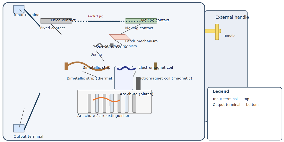
A circuit breaker has several internal parts. Each one has a role, and these parts work together. The main components are simple.

They include fixed contacts and moving contacts. They include a latch, a spring, and a handle. 

They include a thermal element. They include a magnetic coil. The parts are small, but they act with precision.

When everything works together, they protect the system. The next figure shows a cutaway diagram of a circuit breaker’s internal components.

The Operating Mechanism

The operating mechanism keeps the contacts closed. It uses a latch and also employs a spring.

When the breaker is ON, the contacts touch. Electricity flows freely. The latch holds everything in place, but it is fragile by design.

It releases instantly when triggered. As soon as the latch is pushed, the spring snaps open. The contacts separate, and the power stops.

Thermal Trip Mechanism

The thermal trip uses a bimetallic strip. It is made of two metals. They expand differently with heat. Under normal current, the strip is straight. When the current increases, it warms. The metals expand unevenly. 

The strip bends, and this bending pushes on the latch. The latch releases, and the breaker trips. This method detects slow overloads; it is reliable. It reacts to real heat, not just current flow.

Magnetic Trip Mechanism

The magnetic trip reacts to short circuits. It uses a coil. The coil becomes a magnet when a huge current flows. This magnetic force pulls a metal plunger. The plunger hits the latch, and the latch releases. 

The contacts snap open. This action is very fast, and it happens in milliseconds. It saves the system from extreme damage. No heat buildup is needed; just high current triggers it.

Formation of Electric Arc

When contacts open, electricity does not stop instantly. An arc forms. This arc is bright, and it is hot and dangerous.

The arc can melt metals, so it must be controlled immediately. Circuit breakers are designed for this because they use an arc chute. 

The arc chute divides the arc and breaks it into small parts. These parts cool down fast, so the arc disappears. After this process, everything becomes safe again.

Arc Quenching 

Arcs occur at every interruption and even in small circuits arc. If the arc is not extinguished, the breaker will burn, and the contacts will wear out. 

Furthermore, fires may start. The arc chute prevents this by managing the heat and light, and keeps the breaker healthy. This procedure makes breakers last longer and ensures safe disconnection.

Miniature Circuit Breakers

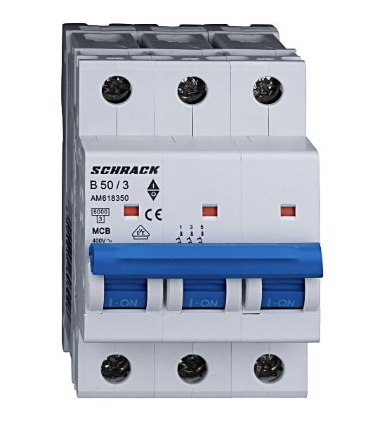
Miniature circuit breakers (MCBs) are common (figure below). They are found in homes, protecting small circuits.

They are compact and easy to use. They also protect against overloads and short circuits.

They can use both thermal and magnetic trip systems. They are installed in distribution boards.

Ground Fault Breakers

Ground Fault Circuit Breakers (GFCI/RCCB). These breakers protect people by detecting imbalances in electrical current.

This imbalance means current is leaking. The leak may be going through a person. It may be going into the ground.

The breaker senses the difference and trips instantly, so this prevents electrocution. These breakers are important in bathrooms. They are also required outdoors since they save lives.

Arc Fault Breakers 

Arc Fault Breakers (AFCI/AFDD). These breakers are designed to detect arcs. Arcs are dangerous, and they occur in damaged wires.

They can also appear in loose connections. They can start fires inside walls. Unfortunately, a regular breaker cannot detect them, but AFCIs can.

They analyze waveforms to sense arc patterns, and they trip before a fire starts. So, they add important protection.

Molded Case Circuit Breakers

Without a doubt, Molded Case Circuit Breakers (MCCBs) are larger in size. They are used in commercial buildings since they can handle higher currents.

They allow adjustable trip settings, which makes protection more precise. They serve machinery and large distribution panels. They have strong housing because they are built for tough conditions.

Air Circuit Breakers

Air Circuit Breakers (ACBs) are used in heavy systems. They control the main feeders and handle very high currents.

They use air to extinguish arcs. They are common in switchgear and are used in large industrial facilities. They offer reliable protection for big loads.

Vacuum Circuit Breakers 

For medium-voltage systems, Vacuum Circuit Breakers (VCBs) VCBs are the best choices. They extinguish arcs in a vacuum. A vacuum has no air, so it stops arcs instantly.

VCBs last a long time because their contacts experience very little wear. They are popular in utility networks.

Oil Circuit Breakers

Oil Circuit Breakers (OCBs) use oil to cool the arc. It also insulates the contacts. High-voltage systems always prefer this kind of breaker.

They handle very strong arcs. They are older technology, but many are still in service.

Resetting a Circuit Breaker

A breaker must be reset after a trip. It cannot simply be pushed ON. First, it must be fully turned off to reset the latch.

It can then be turned back on. If it trips again, something is wrong. If the overload remains, the short circuit is still present. The breaker is giving a warning, and this means it works perfectly.

Signs of Breaker Problems

Like any other electrical device, breakers can fail. They may feel hot and may trip often. They may not stay ON and may sometimes buzz.

They may also smell burnt from time to time. These signs mean trouble. If the breaker appears worn and faulty, it requires immediate attention. A qualified person should inspect the system.

Why Maintenance Matters

Breakers need care because dust can build up, contacts can age, and screws can loosen. In addition, heat can damage insulation.

So, regular maintenance prevents failures. It ensures breakers work when needed, keeps systems safe, and reduces risk.

Breaker Ratings

Breakers have ratings. These include current ratings such as the maximum normal current. They have an interrupting rating.

This is the highest fault current they can stop. They have voltage ratings, and they have trip curves. All of these factors are important, so choosing the wrong breaker can be dangerous.

Choosing the Right Breaker

Each application needs a specific breaker. Homes use MCBs; workshops use MCCBs; and high-voltage systems use VCBs, or OCBs.

Wet areas need GFCIs, while bedrooms may need AFCIs. Engineers or technicians choose based on load classification and environmental conditions. They consider fault level and safety codes, so proper selection prevents accidents.

Conclusion

This article reviewed the role, operation, and importance of circuit breakers in modern electrical systems.

Circuit breakers protect everything around us. They react to overloads and short circuits as well. 

They can stop arcs and keep wires safe. More importantly, they keep people safe. They use thermal and magnetic technology.

They function quickly and also work reliably. From small MCBs to large ACBs and VCBs, they protect every type of electrical system.

Electricity would be hazardous without them. Breakers make our modern world safe, stable, and efficient.

FAQ: What Is a Circuit Breaker?

What is a circuit breaker?

A circuit breaker is a device designed to automatically stop electricity when a fault or overload occurs.

Why is it important?

It prevents fires, equipment damage, and electrical hazards.

How does it work?

It opens its internal contacts when it detects too much current.

What faults does it protect against?

Overloads and short circuits.

How does it sense overloads?

A bimetallic strip bends when heated and triggers the trip.

How does it sense short circuits?

An electromagnet activates instantly when current spikes.

What happens when it trips?

The contacts open and stop the flow of electricity.

Can you reset a circuit breaker?

Yes. You simply switch it back on after fixing the problem.

Where are circuit breakers used?

Circuit breakers find their application in homes, offices, factories, and power distribution systems.

How is a breaker different from a fuse?

A fuse must be replaced; a breaker can be reused.

Are all breakers the same?

No. They come in many ratings and types for different applications.

Do breakers stop every type of fault?

No. Some faults require GFCIs or AFCIs for extra protection.

What is a Motor Starter?

A motor starter is a simple device that controls an electric motor. It is used to safely turn the motor on and off and protect it during operation.

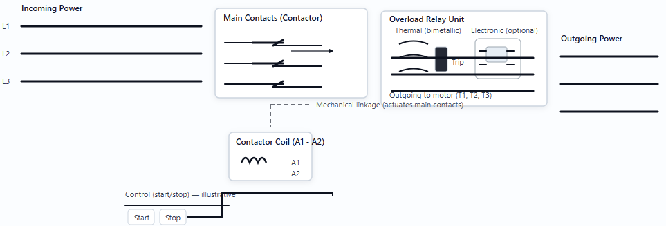
A contactor and an overload relay are combined within a single unit to form a motor starter. 

While the overload relay acts as a safety mechanism, the contactor is the one that connects power to the motor. Starters are essential components in a large number of industrial applications. These include conveyors, fans, and manufacturing equipment, among others. 

They are designed to provide reliability and safety. Faults from overcurrent, power surges, or mechanical faults can be mitigated by the use of starters.

For electrical engineers and technicians, it is crucial to understand how a motor starter works. 

This article reviews what motor starters are, how they work, and their types and applications. 

Basic Components of a Motor Starter

A motor starter is really just a team of a few key parts working together in perfect sync. It is composed mainly of two core components: a contactor and a safety feature called an overload protective relay. 

Sometimes it may contain an extra part, such as a built-in fuse and a circuit breaker. This configuration is referred to as a combination starter. The contactor is basically a tough, heavy-duty electrical switch designed for robust, frequent switching of high currents.

It uses a little magnetic coil to work. When you send power to that coil, it acts like a magnet, pulling the main switch contacts closed and letting electricity zoom to the motor. 

If you cut the power to the coil, a spring instantly pops those contacts open, effectively stopping the motor. The overload relay plays a crucial role as your motor’s personal safety guard. 

Its single job is to constantly watch how much power the motor is pulling in. The relay “trips” if the motor unexpectedly tries to draw too much power for an extended period (perhaps due to a jam). That action cuts the control power, instantly telling the main contactor to shut down everything and safely stop the motor.

How a Motor Starter Works

The operation of a motor starter is a sequence of electrical actions. A user pushes a “Start” button to send a low-voltage signal to the starter’s control circuit.

This control power then energizes the contactor coil. The magnetic force pulls the main power contacts closed instantly.

High-voltage power then flows from the main supply lines through the closed contacts. Furthermore, it passes all the way to the overload relay’s current sensors and finally out to the motor windings. The motor begins to run.

To stop the motor, the user pushes a “Stop” button. This action interrupts the control circuit power.

The contactor coil becomes de-energized, causing the main power contacts to spring open. This stops the flow of electricity to the motor, which causes it to coast to a stop.

When a fault occurs, such as the motor jamming or a bearing seizing, the motor draws excessive current.

The overload relay detects this high current. After a short delay (designed to allow for normal starting surges), the overload trips.

It opens a set of auxiliary contacts in the control circuit, forcing the contactor to drop out and cutting power to the motor.

Motor Inrush Current

Electric motors require a large surge of current when they first start up. This is called inrush current or locked-rotor current. It can be several times higher than the motor’s normal running current. 

A motor starter is designed to handle this massive initial current safely. A basic starter applies the full line voltage immediately. This procedure provides high starting torque but generates a large current spike. 

The overload relay has a built-in time delay mechanism. This delay allows the motor to accelerate to speed without nuisance tripping from the normal inrush current. Once running, the current drops to the normal full-load amperage (FLA).

Types of Motor Starters

Not all applications require full voltage starting. Different kinds of motor starters are available to suit specific needs.

Direct Online (DOL) Starters

This is the most common type. It applies full line voltage to the motor terminals immediately.

They are simple, reliable, and cheap. They are best for small to medium motors where the sudden start is acceptable.

Reduced Voltage Starters

These are used for large motors. They limit the starting current surge and reduce mechanical stress on the machinery.

Common types include wye-delta (star-delta) starters, primary resistor starters, and autotransformer starters.

These methods apply a lower voltage initially, gradually increasing it until the motor reaches full speed.

Soft Starters

These are electronic reduced-voltage starters. They use solid-state components such as IGBTs and SCRs to smoothly ramp up the voltage.

This results in a very smooth start and stop sequence. They offer highly precise control over acceleration and deceleration times.

Variable Frequency Drives (VFDs)

VFDs are the most advanced option when it comes to a motor’s start control. They don’t just start and stop the motor.

They control the motor’s speed throughout its operation by changing both the voltage and the frequency of the power supplied. VFDs also include built-in motor protection.

Applications of Motor Starters

Motor starters are ubiquitous in industrial settings. They are used wherever an electric motor needs-controlled operation. 

  • Pumps and Fans: Starters ensure smooth operation and protection in HVAC and water systems. 
  • Conveyor systems use starters for reliable start/stop cycles. 
  • Machine tools and mixers rely on them for power and safety. 

Starters are found in every manufacturing process, managing motors that drive production. The appropriate type of starter is selected based on the motor-size, load type, and the required starting smoothness.

Combination Starters

A combination starter integrates the components needed to start the motor with a dedicated disconnect mechanism, all housed within a single enclosure. This disconnect can be a switch, a fuse block, a circuit breaker, or another type of switch. 

This design offers enhanced safety and convenience. It ensures that all power to the starter can be completely locked out for maintenance or repair work. This layout meets many industrial safety regulations.

Conclusion

This article explores what motor starters are, how they work, and their types and applications. 

A motor starter is far more than just an on/off switch. It is a vital control and safety device for electric motors.

By combining contactors for power control and overload relays for protection, it ensures reliable and safe industrial operations. 

Whether a simple Direct Online starter or a sophisticated Variable Frequency Drive, the right motor starter is essential for the longevity of the motor and the safety of the operating personnel.

FAQ: What is a Motor Starter?

What is a motor starter?

A motor starter is a device that switches a motor on or off and safeguards it against overloading.

Why is a motor starter needed?

Motors draw very high current at startup; the starter limits damage and provides protection.

What are the main parts?

The main parts are a contactor, which switches ON/OFF, and an overload relay, which protects against excess current.

How does it work?

The start signal energizes the contactor coil, which closes the contacts and allows the motor to run.
If an overload occurs, the relay will trip, opening the contactor and stopping the motor.

Does every motor need a starter?

Small motors sometimes don’t, but protection is still recommended.

What types of starters exist?

There are several types of starters available, including manual starters, DOL, star-delta, soft starters, and VFDs.

What protection does it provide?

Overload, phase loss/single phasing protection, and (with fuses/breakers) short-circuit protection.

Is a starter the same as a motor controller?

No. A controller manages logic; a starter provides switching and protection.