Predictive maintenance is transforming the industrial sector. It uses data to anticipate potential machine failures.
This approach helps companies reduce costs and prevent unplanned stoppages. Predictive maintenance depends on advanced tools.
Programmable Logic Controllers (PLCs) are a key component. PLCs monitor machine conditions in real time.
They collect data such as temperature and vibration. This information allows maintenance teams to address issues before they become serious.
Unlike traditional methods, which repair equipment after failure or follow a fixed schedule, predictive maintenance is proactive. It enhances operational efficiency. It keeps factories running smoothly.
This article surveys the role of PLCs in enabling predictive maintenance. It also explores the benefits, challenges, and future trends of this approach.
Understanding the Basics
Maintenance strategies have evolved over time. Reactive maintenance only addresses problems after a breakdown.
This causes downtime and financial losses. Preventive maintenance follows fixed schedules.
It replaces components regardless of condition, which can waste resources. Predictive maintenance uses real-time sensor data.
It determines when maintenance is truly needed. Machines provide insight into their own health.
This enables targeted interventions. This method saves time. It reduces costs and improves overall factory productivity.
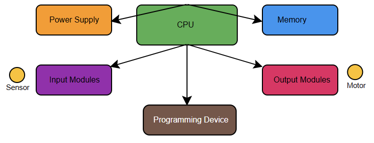
The Role of PLCs in Maintenance
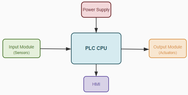
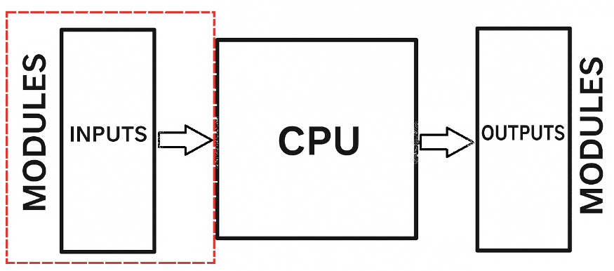
PLCs are industrial grade computers that control machinery. They are extremely reliable.
They can operate in harsh environments. Modern PLCs have advanced capabilities. They can collect and process sensor data quickly.
They form the core of predictive maintenance systems. Acting as the central data hub, PLCs connect machines to analytical software. They serve as the operational brain of the system.
Data Acquisition with PLCs
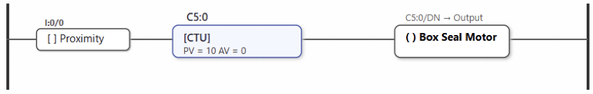
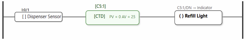
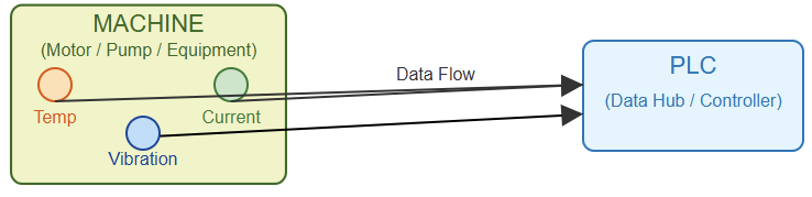
Accurate data is essential for prediction. PLCs collect information from multiple sensors that monitor key machine parameters. Common sensors include vibration detectors. They identify motor or pump wobble.
Temperature sensors indicate potential overheating. Current sensors monitor power usage.
Fluctuations signal potential issues. PLCs continuously capture this data. They convert physical signals into digital form for analysis.
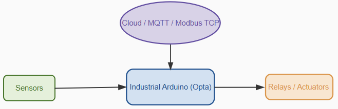
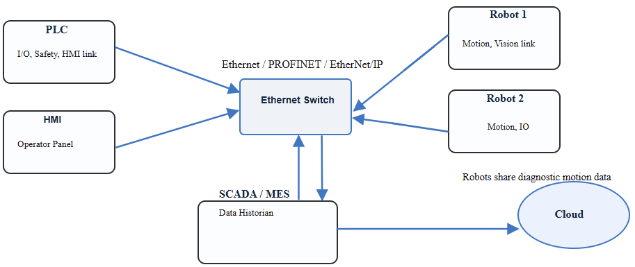
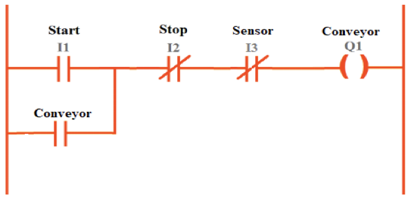
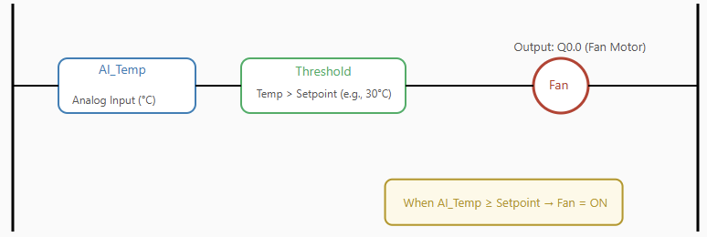
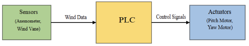
The following figure indicates diagram showing a PLC connected to various sensors on a machine.

Signal Processing and Analysis
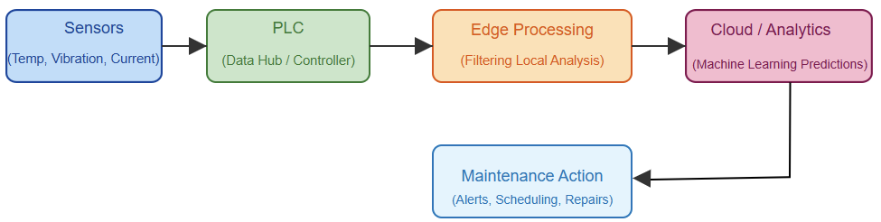
Raw sensor readings alone are insufficient. PLCs can perform basic processing locally.
This is known as edge computing. They filter out noise, check for extreme values, and apply logic rules to make initial decisions.
For more advanced analysis, data is sent to centralized systems or the cloud.
There, machine learning algorithms identify patterns indicating imminent failures. By ensuring high quality data, PLCs improve the accuracy of predictive models.
Communication and Connectivity
Fast and reliable data transfer is critical. PLCs use standard industrial protocols like Ethernet/IP, ProfiNet, and Modbus to connect with other systems. They feed data to SCADA systems for human monitoring.
They also send it to cloud platforms for in-depth analysis. Secure communication is essential. It protects factory networks.
Many modern PLCs include built-in security features. This makes them reliable data gateways.
Machine Learning and Algorithms
Machine learning enables accurate predictions. Algorithms are trained on historical machine data.
They identify normal operating patterns and signs of potential failure. Incoming data is compared against these patterns.
This detects anomalies, estimates time to failure, and recommends maintenance actions.
PLCs provide clean, structured data. This is necessary for algorithms to function effectively.
Common Predictive Maintenance Applications
Many types of machinery benefit from predictive maintenance. Rotating equipment such as motors, pumps, and fans often have predictable wear patterns. Vibration analysis is effective for these machines.
Monitoring temperature is useful for bearing wear. PLCs also optimize energy usage in HVAC systems.
They monitor entire production lines. This provides a comprehensive view of plant health.
Implementation Challenges
Implementing predictive maintenance systems can be complex. Expertise is required to select appropriate sensors.
Integrating older machinery is also challenging. Data management is difficult.

Storing and processing large volumes of information can be costly. Cybersecurity is critical.
Staff need training to use new systems effectively. Overcoming these obstacles demands careful planning and proper resources.
The figure above illustrates a flowchart of a typical predictive maintenance implementation process.
Benefits and ROI
Predictive maintenance delivers substantial returns. It reduces unexpected breakdowns.
It minimizes downtime and lowers maintenance costs. Work is performed only when necessary. This extends equipment life and improves safety.
By predicting failures, dangerous situations are avoided. Overall Equipment Effectiveness (OEE) increases. This enhances competitiveness and operational performance.
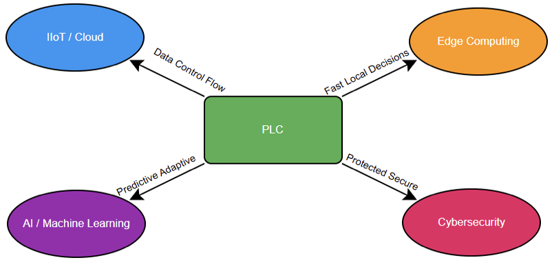
Future Trends and Innovations
The future of maintenance is highly connected and intelligent. Edge computing will become more prevalent.
This allows PLCs to handle complex analysis locally. The Industrial Internet of Things (IIoT) will expand device interconnectivity.
High-speed 5G networks will support faster, more reliable data transmission. Artificial Intelligence (AI) will provide more accurate predictions.
Digital twins virtual models of machines will simulate real world behavior using live PLC data.
Predictive maintenance will continue to evolve toward smarter, fully connected systems.
Case Study: A Manufacturing Plant
A large food processing plant faced frequent pump failures. These failures halted production.
By implementing a predictive maintenance system, PLCs monitored vibration and temperature. Data was analyzed in the cloud.
This predicted a bearing failure a week in advance. Maintenance was scheduled during a planned downtime.
This avoided an emergency shutdown and saved thousands of dollars. This example highlights the real world effectiveness of predictive maintenance.
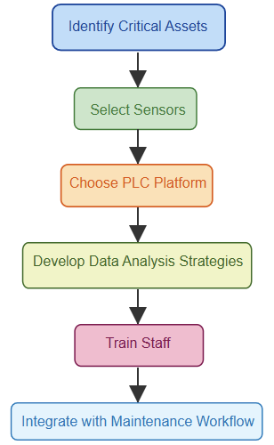
Implementation Guide
Launching a predictive maintenance program requires structured steps. First, identify critical assets where failures cause major downtime. Next, select suitable sensors and high quality hardware.
Choose a PLC platform that supports required communication protocols. Develop data analysis strategies.
Decide on software tools. Finally, train staff and manage change effectively. This ensures adoption.
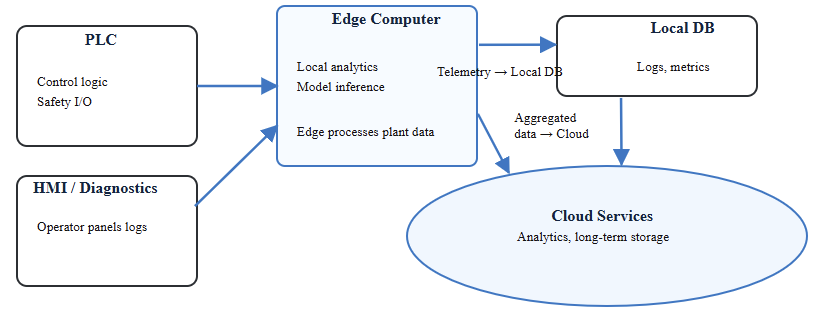
The upcoming figure stipulates a diagram showing different components of a predictive maintenance architecture)

Key Takeaways: Predictive maintenance using PLCs
This article reviewed the significance of predictive maintenance and the pivotal role of PLCs in enabling proactive industrial operations.
Predictive maintenance is a powerful industrial strategy. PLCs are central to its success.
They collect vital machine data and enable intelligent decisions. This approach saves time and money. It improves efficiency and enhances workplace safety. Companies can avoid unexpected breakdowns and costly emergency repairs.
Predictive maintenance also extends the life of machinery and optimizes overall equipment performance.
As factories become increasingly automated, the ability to monitor machine health in real time is essential.
Industries that adopt these technologies gain a competitive advantage. Those that lag behind may face higher costs and increased operational risks.
Looking ahead, AI, IIoT, and digital twins will make predictive maintenance even more precise.
Investing in these systems is more than an operational decision. It is a strategic step toward creating smarter, more resilient, and fully connected factories.
FAQ: Predictive maintenance using PLCs
What is predictive maintenance?
It monitors machine conditions to fix problems before they occur.
How is it different from preventive maintenance?
Preventive follows a fixed schedule; predictive uses real-time data.
What role do PLCs play?
PLCs collect sensor data and send it for analysis.
What data do PLCs monitor?
Temperature, vibration, and current are commonly tracked.
Can PLCs run machine learning?
They do basic processing; advanced analytics run on servers or cloud.
Which communication protocols are used?
Ethernet/IP, ProfiNet, and Modbus.
What are the benefits?
Less downtime, lower costs, longer machine life, better efficiency.
What challenges exist?
Sensor selection, data management, legacy PLC integration, and cybersecurity.
Should old PLCs be upgraded?
Yes. Modern PLCs support better connectivity and analytics.
What’s the future of predictive maintenance?
More AI, edge computing, IIoT, and digital twins.