Programmable logic controllers represent a vital part of the automation setup not only in industries but also worldwide.
They work together with machines, process flows, and safety features in a variety of sectors.
When PLC systems fail, production losses and safety risks quickly increase significantly. Therefore, a structured troubleshooting methodology becomes critical for reliable operations. Random guessing wastes time and may introduce additional faults.
In troubleshooting, engineers’ diagnostic approaches need to be disciplined, repeatable, and technically sound.
Successful troubleshooting is a mixture of electrical knowledge, process understanding, and logical reasoning skills.
On top of that, it requires maintaining accurate records and following the steps of verification in a systematic way each time.
It also demands careful documentation and systematic verification steps consistently. A clear methodology reduces downtime and improves maintenance efficiency considerably.
PLC Troubleshooting Methodology Step by Step
Technicians gain confidence when following organized diagnostic procedures daily. This article explains step-by-step PLC troubleshooting methodology principles.
Step 1: Understanding the Problem Clearly
The first step involves clearly defining the observed problem precisely. Symptoms must be described accurately without assumptions or speculation. Operators should explain what the machine is doing incorrectly now.
Service logs often highlight recurring faults or hidden trends. Always determine whether the issue is electrical, logical, or mechanical. A machine not starting differs from incorrect sequence execution behavior.
Clarifying scope prevents unnecessary modifications to unrelated control sections. Good troubleshooting begins with careful listening and direct observation. Accurate problem statements guide the entire diagnostic process effectively.
The following diagram visually represents the logical decision-making path used during PLC troubleshooting.
It emphasizes sequential validation of power, hardware, and software before implementing corrective actions.
The flowchart reinforces disciplined thinking and reduces the likelihood of unnecessary component replacement or incorrect program modifications

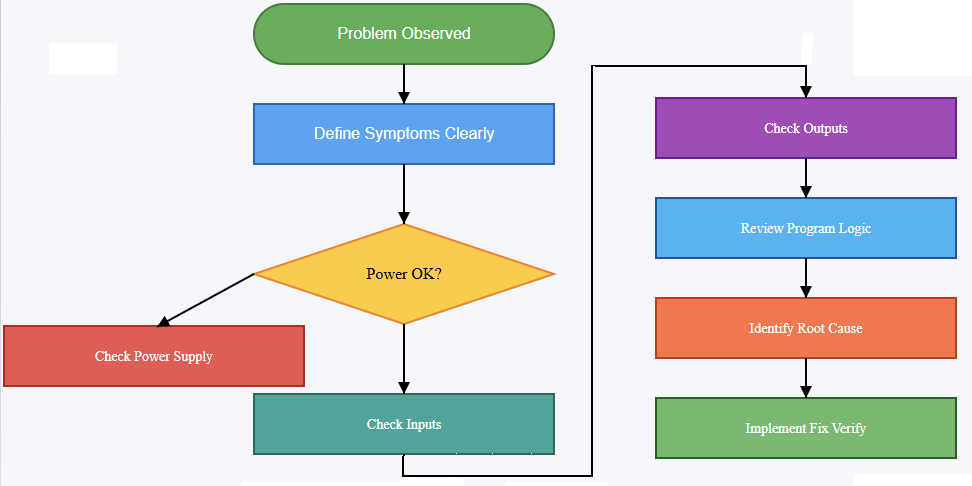
Flowchart of PLC Troubleshooting (step by step)
Step 2: Our Safety and Proper Preparation
Be sure to fully and strictly comply with all safety measures, first of all, if you are going to do diagnostic work.
Lockout and tagout are the ways used to protect workers from the hazard of getting an unexpected energization. Personal protective equipment must match the system voltage levels present.
Never bypass safety circuits without authorized risk assessment documentation. Review electrical drawings and control schematics thoroughly beforehand. Confirm the correct PLC model and firmware version identification clearly.
Verify available programming software matches the controller requirements exactly. Preparation minimizes risk and prevents avoidable configuration errors later. Organized preparation establishes professional discipline in maintenance activities.
Step 3: Verifying Power Supply and Hardware Status
Many PLC issues originate from simple power problems frequently. Check the incoming supply voltage using calibrated measurement instruments properly. Confirm correct voltage levels at PLC power terminals directly.
Inspect power supply modules for overheating or visible damage signs. Observe status LEDs indicating healthy or fault conditions carefully. A flashing error LED often signals configuration or hardware issues.
Loose terminal connections frequently cause intermittent system behavior problems. Grounding integrity should also be verified carefully and methodically.
Stable power conditions form the foundation for reliable operation. Hardware verification eliminates many common faults early and quickly.
Step 4: Checking Input Devices and Field Signals
After confirming power integrity, examine input devices systematically. Verify sensors receive proper operating voltage from control panels consistently. Use multimeters to measure actual input signal states accurately.
Observe PLC input indicator LEDs for state changes visually. If an input never activates, inspect wiring continuity carefully. Broken conductors commonly occur near moving mechanical assemblies.
Confirm the correct sensor type and wiring configuration carefully. Compare field wiring with electrical schematics meticulously and patiently.
Incorrectly wired inputs often mimic complex logical faults misleadingly. Reliable inputs are essential for correct control decisions.
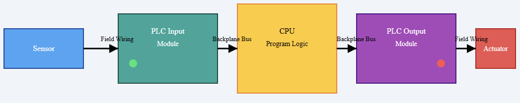
The next diagram illustrates the complete signal path from a field sensor to the final actuator. It helps engineers and technicians understand different important points. These include where to measure voltage, observe LED indicators, and isolate faults.
By visually separating field devices, wiring, and PLC modules, the diagram clarifies how input problems differ from output or logic-related issues.

Step 5: Evaluating Output Devices and Actuators
Outputs must be tested methodically after validating inputs completely. Check output indicator LEDs within the PLC module first. If the LED activates but the device remains off, suspect wiring issues.
Measure output voltage at terminal blocks carefully using instruments. Inspect contactors, relays, and solenoids for mechanical sticking conditions. Overloaded outputs may trigger protection circuits internally sometimes.
Confirm output type matches device electrical characteristics exactly. Never connect inductive loads without proper suppression components installed.
Hardware validation eliminates confusion before software analysis begins logically. Functional outputs confirm that commands reach physical equipment reliably.
Step 6: Reviewing PLC Program Logic Step by Step
Once hardware integrity is confirmed, analyze program logic carefully. Open the ladder diagram or relevant programming language environment. Follow signal flow from inputs toward final outputs sequentially.
Use online monitoring tools to observe rung execution status. Identify whether conditions evaluate as true or false unexpectedly.
Force inputs cautiously only when safe and authorized officially. Examine timers and counters for unexpected accumulated values carefully.
Incorrect preset values frequently cause sequence delays unexpectedly. Look for overwritten variables or duplicate memory addresses systematically.
Logical errors often stem from misunderstood process requirements originally. Structured analysis prevents unnecessary code modifications impulsively.
Step 7: Investigating Communication and Network Issues
Modern PLC systems commonly communicate over industrial networks extensively. Check communication status indicators on network modules carefully. Verify correct IP addresses and network configuration parameters accurately.
Loose Ethernet connectors frequently disrupt communication reliability significantly. Inspect network switches for port status abnormalities immediately. Confirm protocol compatibility between PLC and remote devices clearly.
Review diagnostic buffers for communication timeout messages consistently. Network faults can appear as unpredictable machine behavior symptoms. Reliable communication ensures that coordinated distributed control functions properly.
Step 8: Analyzing Interlocks and Safety Circuits
Interlocks frequently prevent equipment from starting intentionally for safety. Review safety relays and emergency stop circuits carefully always.
Confirm safety contacts are closed under normal conditions consistently. A single open interlock may block entire sequences unexpectedly.
Check guard switches and limit switches’ alignment precisely. Safety PLCs may require separate diagnostic evaluation procedures.
Never bypass safety logic without formal authorization approval. Understanding interlocks prevents misdiagnosing functional protections as faults.
Step 9: Executing Fixes and Verifying Performance
After identifying the root cause, plan corrective action methodically. Avoid making multiple simultaneous changes during repairs unnecessarily. Implement one modification and retest system operation carefully.
Document each change clearly within maintenance records immediately. Replace defective components using approved specifications precisely. Update program comments if logic modifications occur properly.
Confirm that system performance matches the original design requirements fully. Run the machine through complete operational cycles carefully.
Observe performance under normal load conditions attentively. Thorough verification ensures fault elimination without introducing new errors.
Conclusion
This article clarified the systematic methodology for troubleshooting PLC systems step by step.
Structured approaches significantly reduce downtime and operational uncertainty effectively. Beginning with a clear problem definition prevents misguided repair attempts entirely.
Verifying power, inputs, and outputs establishes hardware reliability first. Logical program analysis follows only after confirming electrical integrity.
Communication networks and safety interlocks require equal diagnostic attention always.
Careful corrective actions and thorough verification ensure lasting solutions consistently. Consistent documentation supports future maintenance efficiency improvements significantly. A disciplined mindset ultimately defines successful PLC troubleshooting practice.
Frequently Asked Questions
Why check the power supply first?
A lot of times, power problems cause PLCs to fail; hence, having a stable voltage and good grounding will save you from many troubles.
How important are input and output checks?
Very. Verifying I/O modules, sensors, and actuators ensures the PLC receives and sends correct signals.
When do I cash in on the PLC program logic review?
Once you have made sure that the hardware is okay, you can now check and trial the program sequences and logic for possible errors.
What steps should I take if communication breaks down?
Look for the network cables, connectors, and configurations to bring the communication between the devices and the PLC back.
How can diagnostic tools assist in troubleshooting?
Employ the use of onboard diagnostics, status LEDs, and software logs to locate the fault really fast.
What is the reason behind most of the time PLC throwing errors apart from wiring and power?
Defective I/O modules, dirty code, and environment (heat, dust) are the usual suspects of the PLC.
Is looking at a scene helpful during problem troubleshooting?
Indeed, your eyes will show you the way. A glance will confirm if there is anything such as cables broken, connections loose, or a component heated up.
.
