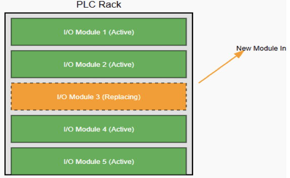
Hot-swapping is the ability to replace or insert components in a system while it is still running and powered. This means there is no need to turn OFF the system or interrupt the process.
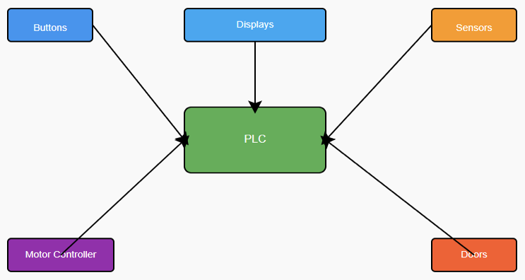
In the world of Programmable Logic Controllers (PLCs), this function is mostly applied to Input/Output (I/O) modules.
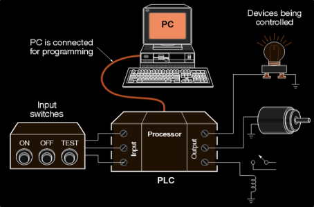
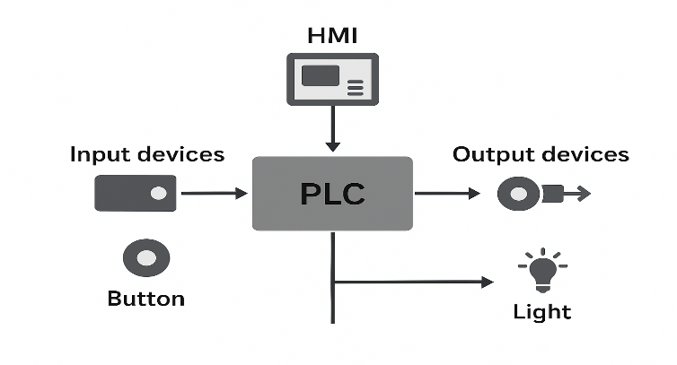
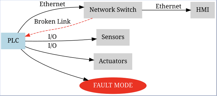
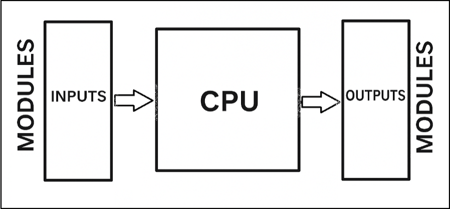
These are the modules that connect the PLC to sensors, actuators, and field devices.
Normally, when a module becomes faulty, the system would need to be stopped, and the power disconnected before replacing the damaged unit. This can cause downtime, lost production, and high costs.
With hot-swapping, however, a technician can pull out the faulty module and slide in a new one while the PLC continues to operate as usual.
This article explains the concept of hot-swapping. It shows its procedures, applications, risks, and finally its advantages and disadvantages.

The Concept of Hot-Swapping
Hot-swapping refers to changing parts of a system while it is still powered on and functioning.
It allows modules to be removed or added without switching off the entire unit. This is very different from cold-swapping.
Cold-swapping requires that the system be completely powered down before any changes are made.
The idea of hot-swapping is not limited to PLCs. It is actually a widely used concept in modern technology.
For example, every time you plug a USB device into your computer while it is running, you are doing a hot-swap. The computer instantly detects the device and makes it available.
Servers and data centers also rely heavily on this feature. They use hot-swappable hard drives, power supplies, and network cards to maintain continuous operation. In PLCs, the function is built into the chassis and the modules.
The modules and their connectors are designed to safely handle insertion and removal while powered. This ensures that the system remains stable and does not crash during the process.
How Hot-Swapping Works in a PLC
For a PLC to allow hot-swapping, both its hardware and software must be specially designed.
It is not something that can be done on just any PLC system. There are several key features that make this possible.
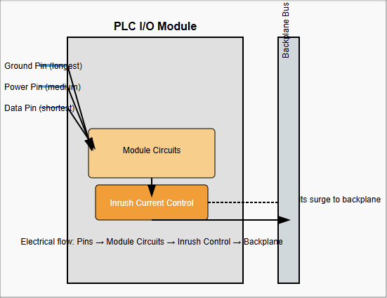
Staggered Pins
Connectors in hot-swappable modules are not uniform. They have pins of different lengths. The ground and power pins are slightly longer.
This ensures they make contact before any data pins do. When inserting a module, the system first gets a stable ground and power connection.
Only then are the data and communication lines connected. Similarly, when removing a module, the data pins disconnect first, preventing corrupted signals or unexpected shutdowns.
Backplane Design
The modules are connected to the CPU through a backplane or communication bus.
In hot-swappable PLCs, this backplane is carefully engineered to withstand the electrical disturbances that happen when a module is inserted or removed.
It includes circuits and controllers that regulate the process. Each module may also contain its own hot-swap controller.
This manages the way the module powers up and synchronizes with the rest of the system.
Inrush Current Control
When a new module is plugged in, it contains capacitors that are empty. The moment power reaches them, they try to charge instantly, causing a sudden surge of current called inrush current.
If not controlled, this surge could disturb or reset other modules on the backplane. A hot-swap controller inside the module limits this inrush. It ensures the current flows gradually and safely.
Software Management
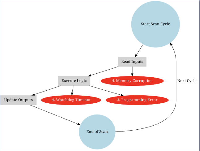
Hardware alone is not enough. The PLC’s operating system and firmware must also recognize when modules are added or removed.
Some PLCs continue to run even if a module is missing. They may show a fault code but keep the program running.
This prevents the whole process from shutting down. Once a new module is inserted, the system automatically detects it, configures it, and re-establishes communication. The program then returns to normal operation without stopping.

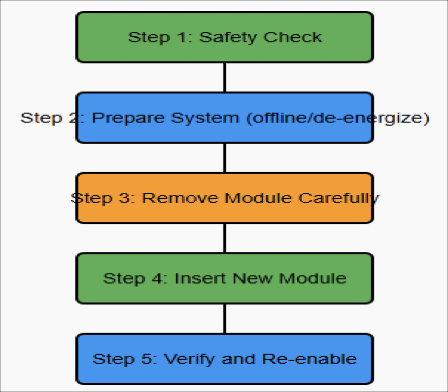
The Hot-Swapping Procedure
Performing hot-swapping must always follow a clear procedure. Doing it incorrectly can lead to damage or safety hazards.
Safety Check
Make sure the module is actually designed for hot-swapping. Not all modules allow this.
Use your hands only. Do not use screwdrivers or metal tools, as they may cause short circuits.
Prepare the System
If possible, use the PLC software to place the module in an “offline” state. For I/O modules, disconnect or de-energize the field devices connected to them. This reduces risk during the swap.
Remove the Module
Unlock the retaining clips or screws. Disconnect the terminal block. Gently slide the module out in a straight motion. Avoid shaking or twisting.
Insert the New Module
Verify that the replacement module is the same type as the original. Align it correctly with the chassis. Push it in firmly until it locks in place.
Verify and Re-enable
Once inserted, the PLC detects the new module. Use the software to confirm communication and function. If you disabled the I/O earlier, re-enable it now. Test to make sure it is working correctly.

Applications of Hot-Swapping
Hot-swapping is most common in advanced PLC systems, particularly those that are modular or rack-based. It is widely used in:
Redundant Systems
In critical plants, two PLCs often run together. One is active, and the other is on standby.
If a module fails, it can be replaced while the standby system keeps things running. This avoids any interruption.
Remote I/O
Many plants use distributed PLC systems with remote I/O racks in different locations.
Hot-swapping makes it possible to change a remote module without affecting the main PLC. The rest of the plant continues running normally.
System Upgrades
Industries often upgrade their equipment step by step. Hot-swapping allows a technician to replace old modules with newer ones while the process continues. This reduces downtime during modernization.
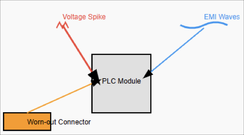
Risks of Hot-Swapping
Although the feature is very useful, it also comes with risks. These include:
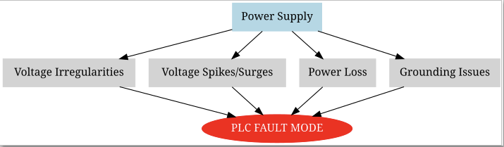
Voltage Surges
If a module is faulty or not designed well, inserting or removing it can create spikes in voltage. These spikes may damage the module or even the backplane.
Electromagnetic Interference (EMI)
The process of swapping can generate electrical noise. This noise may interfere with data communication inside the PLC. It can cause temporary data loss.
Connector Wear
Modules that are swapped too often can wear out their connectors. The metal surfaces can corrode or oxidize over time, leading to poor connections.
Data Integrity
If a module is removed while it is actively transmitting data, that data may be lost or corrupted. PLC firmware must be designed to handle this situation gracefully.

Advantages and Disadvantages of Hot-Swapping in PLCs
This subsection gives a brief explanation of pros and cons of the hot-swapping in PLCs.
Advantages
Reduced Downtime
Processes keep running with minimal interruption. This is crucial for industries that operate nonstop, such as 24/7 production lines.
Improved Reliability
In redundant systems, hot-swapping adds another layer of fault tolerance.
Simplified Maintenance
Technicians can replace or upgrade hardware without shutting down the whole system.
Safer Work
Technicians may not need to completely power down the PLC cabinet, which reduces time spent working in de-energized conditions. However, standard electrical hazards remain.
Disadvantages
Higher Cost
Hot-swappable PLCs are more expensive. Their backplanes and modules require advanced designs.
Complexity
These systems are technically more complex, requiring careful engineering and support.
Strict Procedures
Maintenance staff must follow the right steps. Failure to do so can damage the system.
Key Takeaways: What is Hot-Swapping in PLCs?
Hot-swapping in PLCs is an important step forward in automation technology. It allows modules to be replaced, repaired, or upgraded without stopping the process.
This provides higher reliability and efficiency, which is critical for industries where downtime is very costly.
The advantages are clear: reduced downtime, better reliability, easier maintenance, and improved flexibility.
At the same time, there are challenges. The systems are more expensive, the design is more complex, and the procedures require discipline.
When done properly, hot-swapping offers industries a strong balance between high performance and maintenance convenience.
As plants and factories continue to demand more uptime, hot-swapping will remain a vital feature in modern PLC systems.
It represents not only a technical improvement but also a practical solution for achieving continuous production and high efficiency.
FAQ: What is Hot-Swapping in PLCs?
What does “hot-swapping” mean in PLC systems?
Hot-swapping in PLCs means replacing or inserting a module (often an I/O module) into a PLC rack or chassis while the system remains powered and running—without shutting the PLC (or production) down.
How is hot-swapping different from cold-swapping?
Cold-swapping requires power to be shut off before changing parts. Hot-swapping does not.
With cold swapping, the system is “dead” (no power) when you perform the swap; with hot-swapping, the system continues to run.
Which PLC modules typically support hot-swapping?
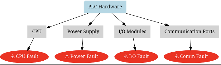
Usually I/O modules (digital or analog), power supply modules, or in some systems, communication modules.
Whether a specific module supports hot-swap depends on the PLC vendor and hardware design.
Some modules are specifically built with hot-swap controllers and staggered power / ground pins.
What hardware features make hot-swapping possible?
Features include:
- Connectors with staggered pins that ensure ground and power connect first, before data or signal pins.
- Hot-swap controllers in modules to control inrush current and protect against overcurrent.
- Design of backplane to tolerate electrical transients and maintain stability as modules are inserted or removed.
What are the software / firmware requirements for hot-swapping?
The PLC firmware must detect the removal / insertion of modules. It must handle missing modules (flag faults) but keep operating if the module isn’t critical.
Once the new module is installed, it must be re-recognized, initialized, and integrated back into the system.
What are the benefits of hot-swapping in PLCs?
Some of the main advantages:
- Reduced downtime (no need to stop the whole system) allowing continuous production.
- Easier maintenance and faster module replacement.
- Fault tolerance and reliability: faulty modules can be replaced without fully shutting down.
- Flexibility to upgrade or change modules with minimal disruption.
What are some of the main risks or drawbacks?
Some are:
- Voltage surges or transients when inserting/removing modules, possibly damaging components.
- Inrush current when new module capacitors charge; if not controlled, it can cause disturbances to other modules.
- Faults during insertion/removal (e.g. communication loss, module detection issues).
- Wear on connectors or poor seating over time.
Are there PLC brands or types where hot-swapping is especially common / safe?
Yes. Higher-end modular PLC systems, rack-based designs, redundant PLC configurations often include hot-swap capable modules.
Some specific PLCs by large vendors offer documented hot-swap I/O modules. In contrast, older or simpler/compact PLCs might not support it or only in limited slots.
What precautions should a technician take when performing hot-swap on PLCs?
Good practice includes:
- Verifying the module is indeed hot-swappable.
- De-energizing or making offline the field devices connected to the module if possible.
- Using hands (not metal tools) to avoid shorting.
- Ensuring the replacement module is correct type/model.
- Monitoring that communication / diagnostic show all good after insertion.
- Being aware of module alignment, seating, and the environment (dust, moisture).
Can hot-swapping be done in every condition and environment?
Not always. Conditions like dirty, wet, or otherwise harsh environments can complicate safe swapping.
Also, if a module is deeply integrated in the process, removing it—even briefly—may cause faults or degrade performance.