PLCs have remained a constant backbone of manufacturing for more than fifty years. Their robustness, ability to withstand harsh industrial environments, and versatility in programming make them indispensable in automotive plants.
Whether it is welding robots on the production line, conveyor belts transporting car bodies, or automated quality checks, PLCs play an essential role in ensuring reliability, precision, repeatability, and efficiency.
This article explores the significance of PLCs in the automotive industry, their applications, benefits, challenges, and future trends shaping their role in modern vehicle production.
Understanding PLCs in Automotive Context
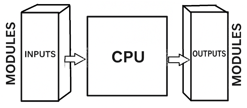
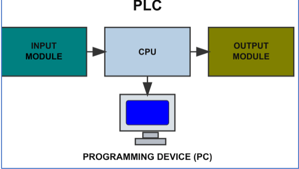
A PLC is a digital computer specifically designed to control electromechanical processes in industrial environments.
It receives input signals from sensors, processes these signals according to a programmed logic.
After that, it sends commands to the output devices such as motors, solenoids, robotic arms, among others.
In automotive manufacturing, this means a PLC could take data from a proximity sensor and detecting the presence of a car chassis.
Next, process that information, and then trigger a robotic arm to weld a joint or move the chassis to the next workstation.
Unlike conventional computers, PLCs are ruggedized. This helps to withstand high temperatures, dust, humidity, and electrical noise typically found in automotive plants.
The flexibility of PLCs also makes them suitable for the dynamic nature of automotive manufacturing.
Production lines often need to be reconfigured for new models. So, PLCs allow engineers to adjust programming rather than rebuild entire control systems as the used to do back then in 1960s.
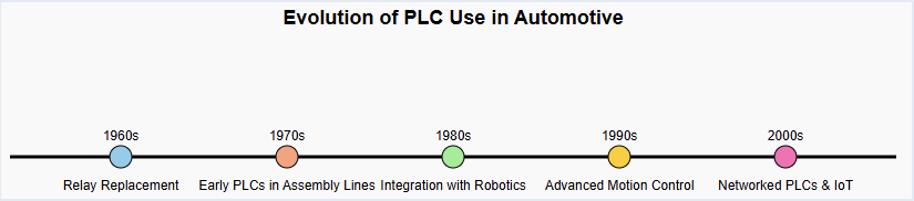
Evolution of PLC Use in Automotive
The first PLCs appeared in the late 1960s, introduced to replace hard-wired relay logic in industries such as automotive. Before PLCs, factories relied on panels full of relays and timers to sequence operations.
These systems were not only bulky and costly but also difficult to modify whenever a new car model was introduced.
The automotive industry, with its high volume and frequent model changes, was among the earliest adopters of PLC technology.
By the 1970s and 1980s, major automakers like Toyota, General Motors, and Ford had integrated PLCs into their production facilities.
PLCs became essential for controlling stamping presses, welding machines, painting booths, and conveyor systems.
As cars became more sophisticated and factories moved toward mass customization, PLCs evolved as well. Modern PLCs support high speed processing, advanced networking, safety protocols, and even integration with enterprise-level systems.
This evolution has aligned perfectly with the automotive sector’s push toward lean manufacturing and Industry 4.0.

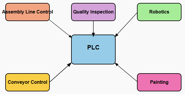
Key Applications of PLCs in Automotive Manufacturing
The automotive factory is a vast and complex ecosystem that integrates mechanical, electrical, and digital systems. PLCs serve as the control nerve center across various stages of production.
Painting and Coating
Painting is one of the most sensitive processes in car manufacturing. PLCs regulate temperature, humidity, and spray patterns to achieve a flawless finish while minimizing material waste.
Assembly Line Automation
One of the most visible applications of PLCs is in assembly line control. From moving a chassis through different stations to synchronizing robotic arms.
PLCs ensure that every component is added at the right time and in the right sequence.
This coordination minimizes downtime and guarantees a smooth flow of production.
Robotic Welding
Modern automotive plants rely heavily on robotic welding for precision and speed. PLCs monitor welding parameters, control robot movement, and ensure safety interlocks are followed.
With PLCs, thousands of welds on a single car body can be completed with micron-level accuracy.
Automated paint shops rely on PLC-controlled robots to deliver consistent coating thickness and quality.
Conveyor and Material Handling
PLCs manage conveyor belts, lifts, and automated guided vehicles (AGVs) that move parts and assemblies across the plant.
The precise timing and synchronization of these systems prevent bottlenecks and allow just-in-time manufacturing.
Quality Control and Inspection
Automotive production demands strict quality assurance. PLCs control automated testing rigs that check parameters such as engine performance, braking systems or electrical circuits.
Then, Sensors feed real-time data into the PLC, which determines whether a component passes or fails the test.
Safety Systems
Worker safety is important in environments filled with heavy machinery and robotics.
PLCs are often integrated with emergency stop systems and light curtains. Then proceeding with interlocks to immediately halt operations if unsafe conditions are detected.

Benefits of PLCs in Automotive Industry
The integration of PLCs into automotive plants delivers several advantages that go beyond simple automation.
Reliability
Automotive production requires long hours of continuous operation, and PLCs are designed to run non-stop with minimal downtime.
Their rugged design ensures that they can withstand harsh conditions while maintaining accuracy.
Flexibility
Automotive plants must frequently reconfigure lines to accommodate new models or variations.
PLCs allow engineers to reprogram control logic quickly, avoiding costly rewiring or hardware changes.
Efficiency
By managing complex processes with precision, they reduce waste, optimize resource utilization, and improve throughput.
This efficiency translates into lower production costs and faster time to market.
Quality assurance
Quality assurance cannot be overstated. By automating inspection and testing, they minimize human error and ensure consistent standards across millions of units.
Safety
Through integration with safety devices and adherence to standards such as IEC 61508. So, PLCs ensure that dangerous processes can be immediately halted in emergencies, protecting both workers and equipment.
Integration with Industry 4.0
The automotive industry is at the forefront of Industry 4.0 industrial revolution. This industry is characterized by cyber-physical systems, IoT connectivity, and data-driven decision-making.
PLCs, though a legacy technology, have evolved to integrate seamlessly into this new digital ecosystem.
Modern PLCs are not just standalone controllers. They feature Ethernet/IP, ProfiNet, and Modbus TCP/IP communication protocols, enabling them to connect with higher-level Manufacturing Execution Systems (MES). Also, with Enterprise Resource Planning (ERP) systems.
This connectivity ensures real-time visibility into production data, which is essential for predictive maintenance, supply chain optimization, and quality control.
With embedded data logging and connectivity, PLCs act as bridges between the shop floor and the cloud.
This capability supports advanced analytics, machine learning applications, and remote monitoring.
For example, a PLC controlling a robotic welder can transmit data about weld quality and equipment health to a central dashboard, allowing engineers to detect issues before they cause costly downtime.
Key Takeaways: PLC in the Automotive Industry
The significance of PLCs in the automotive industry was detailed in this article. Their applications, benefits, challenges, and future trends were also addressed successfully.
Their ability to control complex processes, adapt to new requirements, and integrate with digital platforms makes them indispensable in an industry that constantly evolves.
While challenges such as cost, skills shortage, and cybersecurity remain, the continued advancement of PLCs ensures they will remain a cornerstone of automotive automation for decades to come.
As the automotive world transitions toward electric mobility, sustainable practices, and smart factories, PLCs will continue to serve as the silent yet powerful brains behind the machines that build the cars of the future.
FAQ: PLC in the Automotive Industry
What is a PLC and how did it originate in automotive manufacturing?
A Programmable Logic Controller (PLC) is a ruggedized industrial computer that monitors inputs, processes them to obtain the desired output that control the actuators (motor, lamps)
What are the key applications of PLCs in automotive manufacturing?
Used in painting and coating, assembly line automation, robot welding, conveyor and material handling, quality control and inspection, among others
How are automotive PLC applications evolving with Industry 4.0?
Modern PLCs are not just standalone controllers theyfeatureEthernet/IP, ProfiNet, and Modbus TCP/IP communication protocols
What are the benefits of PLCs in the automotive industry?
They provide a number of benefits such as reliability precision, repeatability, and efficiency, to mention the few.