Proximity sensors are essential components in the development of automated and intelligent systems.
They can sense objects without physical contact. This capability has made them indispensable in industries such as manufacturing and automotive.
They are also widely used in consumer electronics and home automation. Understanding the different types of sensors and how they function is important. It also helps to know their potential applications.
This knowledge allows engineers and system designers to choose the most suitable sensor for optimal performance and reliability.
This article reviews the different types of proximity sensors, how they work, their applications, and their advantages in modern systems.
How Proximity Sensors Work
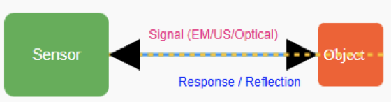
Proximity sensors detect objects by emitting a signal. This signal can be electromagnetic, ultrasonic, or optical. The sensor monitors any changes caused by an object entering its detection field. The detection mechanism depends on the sensor type:
- Inductive sensors sense variations in magnetic fields caused by metal objects.
- Capacitive sensors detect changes in capacitance due to nearby materials. They work for both metallic and non-metallic objects.
- Ultrasonic sensors measure the time it takes for sound waves to reflect off an object.
- Optical or photoelectric sensors use light beams to identify interruptions or reflections caused by objects.
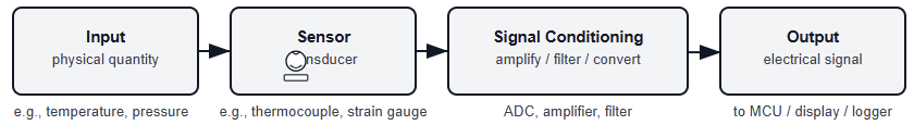
Once the sensor detects the signal, it converts it into an electrical output. This output can trigger actions such as starting a motor, opening a gate, or counting items on a conveyor belt.
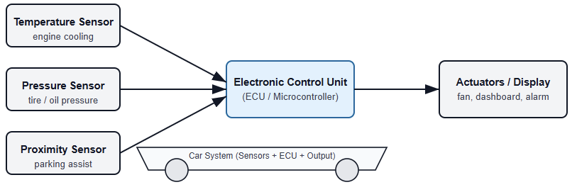
The following figure illustrates block diagram showing a sensor emitting a signal (electromagnetic, ultrasonic, or optical) and receiving a response when an object enters the field.

Types of Proximity Sensors
Inductive Proximity Sensors
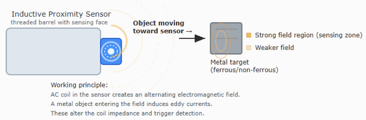
These sensors detect only metal objects. They operate using electromagnetic induction. When a metal target enters the sensor’s magnetic field, it disturbs the field.
This disturbance generates a response. They are widely used in industries to detect metal components, such as gears or metal fragments.
Capacitive Proximity Sensors
Capacitive sensors detect both metallic and non-metallic materials, including plastics, glass, and wood.
They operate based on the target material’s capacitance. Common applications include fluid level detection, packaging lines, and presence detection of objects.
Ultrasonic Proximity Sensors
These sensors utilize high-frequency sound waves to locate objects. The sensor emits a sound pulse and measures the time it takes for the echo to return. This determines the object’s distance.
They are ideal for distance measurement, detecting objects in dusty environments, and sensing transparent materials.
Infrared (IR) Proximity Sensors
IR sensors use infrared light to detect nearby objects. They emit an IR beam and sense its reflection to identify objects in the area.
Applications include smartphones, for turning screens on or off during calls. They are also used in automatic faucets and simple obstacle detection in robotics.
Photoelectric Proximity Sensors
Photoelectric sensors detect objects using a light beam. They come in three varieties:
- Through-beam: The emitter and receiver face each other. An object is detected when it interrupts the beam.
- Retroreflective: The emitter and receiver are on one side, with a reflector opposite. Detection occurs when the beam is interrupted.
- Diffuse: The sensor detects light reflected directly off the object.
Magnetic Proximity Sensors
Magnetic sensors respond to changes in magnetic fields. They often use reed switches or Hall effect sensors. They are common in industrial limit switches and security systems.
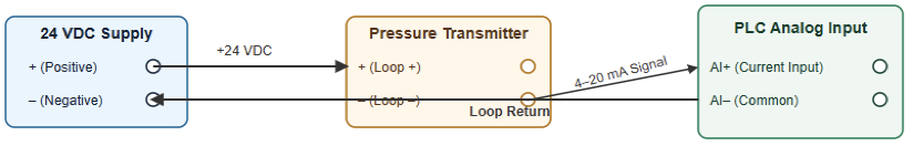
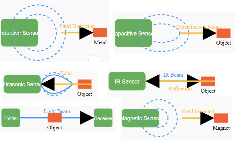
Examples include monitoring doors and windows. The next figure indicates a diagram of the proximity sensor (inductive, capacitive, ultrasonic, infrared, magnetic) detecting a metal or object.

Applications of Proximity Sensors
Industrial Automation
Proximity sensors are crucial in manufacturing. They detect items on assembly lines, control robotic arms, and provide warnings to prevent collisions or operational errors.
Automotive Systems
In vehicles, these sensors support parking, object detection, automatic braking, and seat belt reminders. They enhance both safety and user convenience.
Consumer Electronics
IR-based proximity sensors are found in smartphones and tablets. They turn off screens during calls. They are also used in touchless home appliances such as automatic faucets and soap dispensers.
Medical Equipment
Proximity sensors help monitor fluid levels. They control automated functions in patient care devices. They also support hygienic, contactless operation.
Smart Home and IoT Devices
They are used in lighting systems, security automation, and energy-saving applications. They detect occupancy and control devices accordingly.
Security Systems
Proximity sensors detect unauthorized entry. They monitor doors and windows. They help manage restricted areas without physical contact.
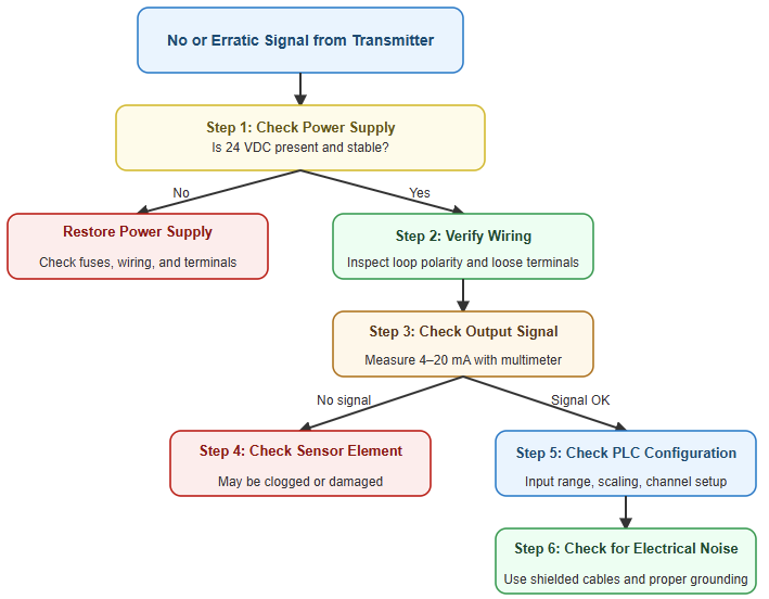
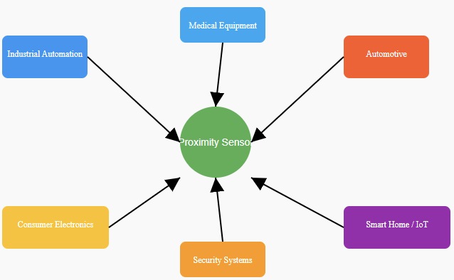
The upcoming figure shows Illustration of general applications of proximity sensor as mentioned above.

Advantages of Proximity Sensors
High-Speed Response
Proximity sensors detect objects almost instantly. This makes them suitable for high-speed automation and real-time monitoring.
Reliable in Harsh Conditions
Since they do not rely on physical contact or optical clarity, many sensors remain accurate in dirty, greasy, or hazardous environments. Examples include food processing, chemical plants, and mining.
Compact and Flexible Design
Available in various sizes, from small surface-mount devices to large industrial units. They can easily integrate into embedded systems or circuit boards.
Energy Efficiency
Proximity sensors generally consume minimal power, especially when idle. This makes them ideal for battery-powered devices, IoT applications, and portable systems.
Enhanced Safety and Automation
Their reliability allows safe operation in accident prevention, machinery protection, elevators, and autonomous vehicles. This reduces the need for human intervention.
Long Service Life
With no moving parts to wear out, proximity sensors offer extended operational life. They are capable of millions of cycles without degradation.
Easy Installation and Maintenance
They require minimal calibration and are simple to install. Many models support plug-and-play integration with PLCs, controllers, or digital systems.
Choosing the Right Proximity Sensor
Depending on the selection factor (application), this is how the proximity sensor can be chosen
- Sensing Range: Maximum distance at which objects can be detected.
- Target Material: Type of object, such as metallic, non-metallic, transparent, or liquid.
- Environmental Conditions: Ability to withstand temperature, moisture, dust, and vibration.
- Mounting & Size: Compact sensors may be needed for limited spaces.
- Output Type: Options include analog, digital, normally open (NO), or normally closed (NC).
- Integration Options: Compatibility with PLCs, microcontrollers, or other control systems.
Installation Tips and Best Practices
- Mount sensors securely to avoid vibration errors.
- Avoid areas with strong magnetic or electrical fields.
- Reduce EMI with proper wiring and grounding.
- Adjust sensors according to manufacturer specifications.
- Test sensing range and outputs before deployment.
Future Trends in Proximity Sensor Technology
Future trends in proximity sensor technology include miniaturization for wearable and portable devices.
This allows them to be easily integrated into small systems. Intelligent sensors with built-in processing are becoming more common.
They enable faster and more autonomous decision-making. Wireless integration through Bluetooth, Zigbee, or Wi-Fi is also on the rise. This improves connectivity and data sharing.
Additionally, AI-driven adaptive learning and predictive maintenance are being incorporated to enhance performance. They help anticipate failures. They also optimize sensor operation in real time.
Sensors are becoming more energy-efficient. This is crucial for battery-powered and IoT applications.
Another trend is the development of multi-functional sensors. These combine several detection methods into a single device.
Finally, there is a growing focus on enhanced durability and reliability. This ensures sensors can withstand harsh industrial and outdoor environments.
Key Takeways: Types of Proximity Sensor
This article reviewed proximity sensors and their role in automation and intelligent systems. Proximity sensors detect objects without physical contact. This feature makes them safe and reliable.
They are widely used in manufacturing. They help control machinery and manage assembly lines. In the automotive industry, they support parking, object detection, and safety systems.
In consumer electronics, they help manage smartphones and smart home devices. Medical equipment also benefits from contactless sensing. Proximity sensors improve efficiency. They also reduce wear on mechanical components.
Understanding the different types and how they work is essential. Engineers and system designers can then select the right sensor for each application. Proper selection ensures maximum performance, reliability, and safety.
FAQ: Types of Proximity Sensor
What is a proximity sensor?
A device that detects objects without physical contact.
What are the main types of proximity sensors?
Inductive, capacitive, ultrasonic, optical/photoelectric, and magnetic.
How do inductive sensors work?
They detect metal objects by sensing changes in a magnetic field.
Can capacitive sensors detect non-metal objects?
Yes. They sense changes in capacitance from metal or non-metal objects.
Difference between ultrasonic and optical sensors?
Ultrasonic uses sound waves; optical uses light beams.
What factors should I consider when choosing a sensor?
Target material, range, environment, speed, and output type.
What are common limitations?
Inductive: metal only. Capacitive: sensitive to environment. Optical: line-of-sight required.
Where are proximity sensors used?
Industrial automation, smartphones, automotive systems, and smart home devices.