PLC in the Automotive Industry

PLCs have remained a constant backbone of manufacturing for more than fifty years. Their robustness, ability to withstand harsh industrial environments, and versatility in programming make them indispensable in automotive plants. 

Whether it is welding robots on the production line, conveyor belts transporting car bodies, or automated quality checks, PLCs play an essential role in ensuring reliability, precision, repeatability, and efficiency.

This article explores the significance of PLCs in the automotive industry, their applications, benefits, challenges, and future trends shaping their role in modern vehicle production.

Understanding PLCs in Automotive Context

A PLC is a digital computer specifically designed to control electromechanical processes in industrial environments.

It receives input signals from sensors, processes these signals according to a programmed logic.

After that, it sends commands to the output devices such as motors, solenoids, robotic arms, among others.

In automotive manufacturing, this means a PLC could take data from a proximity sensor and detecting the presence of a car chassis.

Next, process that information, and then trigger a robotic arm to weld a joint or move the chassis to the next workstation. 

Unlike conventional computers, PLCs are ruggedized. This helps to withstand high temperatures, dust, humidity, and electrical noise typically found in automotive plants.

The flexibility of PLCs also makes them suitable for the dynamic nature of automotive manufacturing. 

Production lines often need to be reconfigured for new models. So, PLCs allow engineers to adjust programming rather than rebuild entire control systems as the used to do back then in 1960s.

Evolution of PLC Use in Automotive

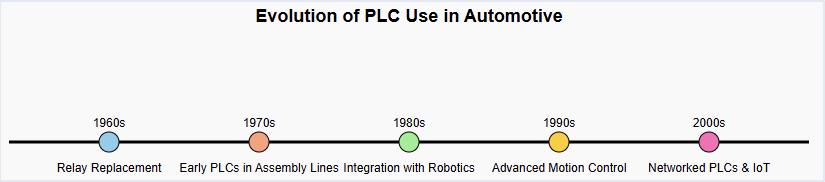
The first PLCs appeared in the late 1960s, introduced to replace hard-wired relay logic in industries such as automotive. Before PLCs, factories relied on panels full of relays and timers to sequence operations. 

These systems were not only bulky and costly but also difficult to modify whenever a new car model was introduced.

The automotive industry, with its high volume and frequent model changes, was among the earliest adopters of PLC technology.

By the 1970s and 1980s, major automakers like Toyota, General Motors, and Ford had integrated PLCs into their production facilities.

PLCs became essential for controlling stamping presses, welding machines, painting booths, and conveyor systems.

As cars became more sophisticated and factories moved toward mass customization, PLCs evolved as well. Modern PLCs support high speed processing, advanced networking, safety protocols, and even integration with enterprise-level systems. 

This evolution has aligned perfectly with the automotive sector’s push toward lean manufacturing and Industry 4.0.

PLC in the Automotive Industry

Key Applications of PLCs in Automotive Manufacturing

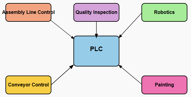
The automotive factory is a vast and complex ecosystem that integrates mechanical, electrical, and digital systems. PLCs serve as the control nerve center across various stages of production.

Painting and Coating

Painting is one of the most sensitive processes in car manufacturing. PLCs regulate temperature, humidity, and spray patterns to achieve a flawless finish while minimizing material waste. 

Assembly Line Automation

One of the most visible applications of PLCs is in assembly line control. From moving a chassis through different stations to synchronizing robotic arms.

PLCs ensure that every component is added at the right time and in the right sequence. 

This coordination minimizes downtime and guarantees a smooth flow of production.

Robotic Welding

Modern automotive plants rely heavily on robotic welding for precision and speed. PLCs monitor welding parameters, control robot movement, and ensure safety interlocks are followed.

With PLCs, thousands of welds on a single car body can be completed with micron-level accuracy.

Automated paint shops rely on PLC-controlled robots to deliver consistent coating thickness and quality.

Conveyor and Material Handling

PLCs manage conveyor belts, lifts, and automated guided vehicles (AGVs) that move parts and assemblies across the plant.

The precise timing and synchronization of these systems prevent bottlenecks and allow just-in-time manufacturing.

Quality Control and Inspection

Automotive production demands strict quality assurance. PLCs control automated testing rigs that check parameters such as engine performance, braking systems or electrical circuits.

Then, Sensors feed real-time data into the PLC, which determines whether a component passes or fails the test.

Safety Systems

Worker safety is important in environments filled with heavy machinery and robotics.

PLCs are often integrated with emergency stop systems and light curtains. Then proceeding with interlocks to immediately halt operations if unsafe conditions are detected.

Benefits of PLCs in Automotive Industry

The integration of PLCs into automotive plants delivers several advantages that go beyond simple automation.

Reliability

Automotive production requires long hours of continuous operation, and PLCs are designed to run non-stop with minimal downtime.

Their rugged design ensures that they can withstand harsh conditions while maintaining accuracy.

Flexibility

Automotive plants must frequently reconfigure lines to accommodate new models or variations.

PLCs allow engineers to reprogram control logic quickly, avoiding costly rewiring or hardware changes.

Efficiency

By managing complex processes with precision, they reduce waste, optimize resource utilization, and improve throughput.

This efficiency translates into lower production costs and faster time to market.

Quality assurance

Quality assurance cannot be overstated. By automating inspection and testing, they minimize human error and ensure consistent standards across millions of units.

Safety

Through integration with safety devices and adherence to standards such as IEC 61508. So, PLCs ensure that dangerous processes can be immediately halted in emergencies, protecting both workers and equipment.

Integration with Industry 4.0

The automotive industry is at the forefront of Industry 4.0 industrial revolution. This industry is characterized by cyber-physical systems, IoT connectivity, and data-driven decision-making.

PLCs, though a legacy technology, have evolved to integrate seamlessly into this new digital ecosystem.

Modern PLCs are not just standalone controllers. They feature Ethernet/IP, ProfiNet, and Modbus TCP/IP communication protocols, enabling them to connect with higher-level Manufacturing Execution Systems (MES). Also, with Enterprise Resource Planning (ERP) systems.

 This connectivity ensures real-time visibility into production data, which is essential for predictive maintenance, supply chain optimization, and quality control.

With embedded data logging and connectivity, PLCs act as bridges between the shop floor and the cloud.

This capability supports advanced analytics, machine learning applications, and remote monitoring. 

For example, a PLC controlling a robotic welder can transmit data about weld quality and equipment health to a central dashboard, allowing engineers to detect issues before they cause costly downtime.

Key Takeaways: PLC in the Automotive Industry

The significance of PLCs in the automotive industry was detailed in this article. Their applications, benefits, challenges, and future trends were also addressed successfully. 

Their ability to control complex processes, adapt to new requirements, and integrate with digital platforms makes them indispensable in an industry that constantly evolves. 

While challenges such as cost, skills shortage, and cybersecurity remain, the continued advancement of PLCs ensures they will remain a cornerstone of automotive automation for decades to come.

As the automotive world transitions toward electric mobility, sustainable practices, and smart factories, PLCs will continue to serve as the silent yet powerful brains behind the machines that build the cars of the future.

FAQ: PLC in the Automotive Industry

What is a PLC and how did it originate in automotive manufacturing?

A Programmable Logic Controller (PLC) is a ruggedized industrial computer that monitors inputs, processes them to obtain the desired output that control the actuators (motor, lamps)

What are the key applications of PLCs in automotive manufacturing?

Used in painting and coating, assembly line automation, robot welding, conveyor and material handling, quality control and inspection, among others

How are automotive PLC applications evolving with Industry 4.0?

Modern PLCs are not just standalone controllers theyfeatureEthernet/IP, ProfiNet, and Modbus TCP/IP communication protocols 

What are the benefits of PLCs in the automotive industry?

They provide a number of benefits such as reliability precision, repeatability, and efficiency, to mention the few.

Why Is My PLC Output Not Working?

Programmable Logic Controllers (PLCs) are the heart of modern industrial automation.

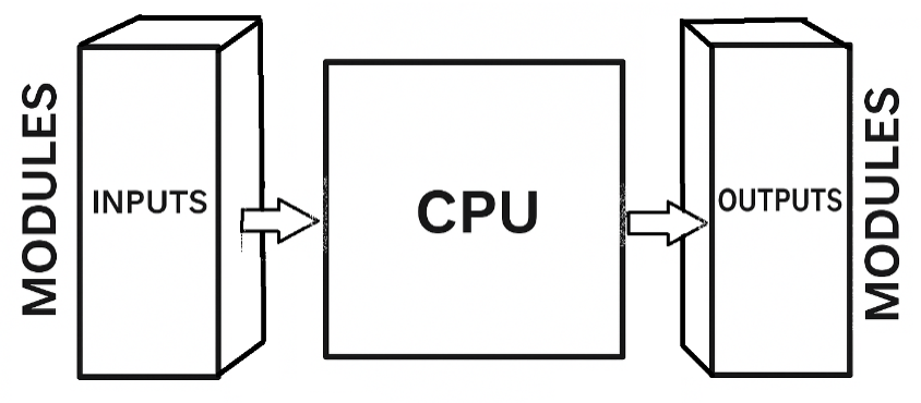
They monitor inputs, and through outputs, they bring systems to life. But what happens when you download your program, set everything up, run the PLC and nothing comes output not working?

This problem is one of the most common headaches for engineers, technicians, and even students learning PLCs.

It is headache cause could be almost anywhere, in the program, in the hardware, in the wiring, or even in the external power supply.

So, this article explores the different reasons a PLC output may not respond, how to approach troubleshooting without, and how to prevent these issues from happening again.

Understanding PLC Outputs

To understand why an output isn’t working, we first need to understand what a PLC output actually is. 

An output is the way a PLC communicates with the outside world. If the input side is like our human senses, the outputs are the hands and voice that make things happen. 


Depending on the application, outputs can be switching a relay, turning a motor on, or energizing a solenoid.

Types of PLC Outputs

Different PLCs have different output modules, and this matters when troubleshooting.

Relay Outputs

Think of them as little switches inside the PLC. They’re versatile because they can handle both AC and DC loads, but they’re relatively slow.

Transistor Outputs

These are fast and reliable for DC applications, commonly used when precision is needed 

TRIAC Outputs

These are designed for AC loads such as lamps, heaters, and solenoids. They’re slower than transistors but ideal for AC switching.

Each type has strengths and weaknesses. Knowing which one you’re using is essential. A common mistake is connecting the wrong type of load to the wrong output module.

How PLC Output Problems Show Up

A PLC output that isn’t working doesn’t always fail in the same way. Sometimes it’s obvious, other times it’s subtle. Here are common symptoms:

  • The PLC software shows the output is ON, but the field device doesn’t respond.
  • The output never turns ON, even though the program conditions seem right.
  • The output works but behaves erratically, flickering or dropping out.
  • The output seems frozen, stuck either ON or OFF.

Each symptom is like a clue that points you closer to the real cause.

Why Isn’t My PLC Output Working?

Now let’s look at the most common culprits, explained in plain language.

The Program Isn’t Doing What You Think

The number one cause isn’t hardware — it’s the logic itself. Maybe the conditions in your rung don’t actually turn on the output, or maybe another part of the program is switching it off again. 

In some cases, the program may require the machine to be in “Auto” mode, but you’re testing it in “Manual.”

What to do

Go online with the PLC and watch the logic in real time. If the output coil isn’t energizing in the software, the issue is with your code, not the hardware.

The Output Has Been Forced

Most PLC software allows inputs and outputs to be forced ON or OFF for testing. If someone forced an output OFF before and forgot to clear it, no amount of correct logic will bring it back.

What to do

Always check if any outputs are forced. Clear them before running the program.

Power Supply Problems

Outputs usually require an external power supply for example, a 24 VDC transistor output needs that 24 VDC source to energize the load. If that supply is missing, disconnected, or incorrectly wired, the output won’t work.

What to do

Measure the voltage at the PLC’s output terminal with a multimeter. If no voltage is present, trace the wiring back to the power supply.

Protection Devices Have Tripped

Many PLC output modules are protected by fuses or circuit breakers. If a short circuit or overcurrent occurred, the fuse may have blown, silently cutting off the output.

What to do

Inspect the module for fuses or check the control panel for tripped breakers. Replace or reset as needed, but also investigate why the fuse blew in the first place.

Wiring Mistakes

Incorrect wiring is one of the simplest yet most common reasons for output problems. Maybe the common terminal wasn’t connected, maybe the polarity is reversed, or maybe a wire has come loose.

What to do

Trace the wiring carefully. Confirm with a continuity tester that the path from PLC to device is intact. Don’t overlook simple things like loose screws or corroded terminals.

The Load Device Itself Has Failed

Sometimes the PLC is working perfectly, but the motor, valve, or lamp is faulty. For example, a solenoid coil could be burned out, or a lamp filament could be broken.

What to do

Test the device independently by applying power directly to it. If it doesn’t respond, replace it.

The Output Module Has Failed

Just like any other electronic device, PLC modules can fail. Surges, overheating, or overloading can damage them.

Symptoms include outputs that never energize, outputs that are stuck ON, or modules that smell burnt.

What to do

If your PLC has spare channels, try moving the output to another one. If that works, the module channel is bad. If not, you may need to replace the entire module.

Wrong Output Type for the Load

It is a classic mistake: connecting an AC load to a DC output or vice versa. A transistor output will never drive an AC lamp, no matter how perfect your wiring is.

What to do

Double-check that the load matches the output type (relay, transistor, or TRIAC).

Electrical Noise or Interference

In noisy industrial environments, electromagnetic interference (EMI) can cause strange behavior. Outputs may chatter, flicker, or respond inconsistently.

What to do

Improve grounding, use shielded cables, and add suppression devices like RC snubbers or diodes.

PLC CPU or System Faults

Finally, though rare, the PLC’s brain itself may have issues. A hardware fault in the CPU or a major error in the system could stop outputs from updating.

What to do

Check diagnostic LEDs, review error codes, and, if necessary, perform a restart.

A Logical Approach to Troubleshooting

When you face a dead output, the worst thing you can do is panic and start changing everything at once. A structured approach saves time and prevents mistakes.

  1. Start with the program: Is the coil actually ON in the software?
  2. Check for forces: Make sure the output isn’t locked out.
  3. Look at indicators: Most PLC output modules have LEDs that show if they’re active.
  4. Measure with a meter: Is voltage present at the terminal?
  5. Trace the wiring: Is the connection to the load solid?
  6. Test the load: Does it work with an independent power source?
  7. Inspect protection devices: Any blown fuses or tripped breakers?
  8. Try another channel or module: To rule out hardware failure.
  9. Review system diagnostics: Are there CPU or module error codes?

This step-by-step process narrows down the possibilities quickly and logically.

Preventing Output Problems Before They Happen

Troubleshooting is necessary, but prevention is better. Here are best practices to avoid output issues in the first place:

  • Choose the right module for your load — don’t overload channels or use the wrong type.
  • Wire correctly and neatly, following manufacturer diagrams.
  • Use protective devices such as fuses, breakers, and surge suppressors.
  • Maintain equipment regularly, tightening terminals and checking loads.
  • Write clean, documented code so logic errors are less likely.
  • Test devices periodically so you catch failing components before they cause downtime.

Key takeaways: Why Is My PLC Output Not Working?

In this article, we addressed the causes, troubleshooting steps, and preventive measures to solve output-related issues in PLCs. Because a non-working PLC output is not a mystery. 

With a clear understanding of PLC hardware and a structured troubleshooting approach, you can bring systems back online quickly and prevent downtime in the future. When a PLC output is not working, it can bring entire systems to a halt. 

Fortunately, most problems can be traced to logical errors, wiring issues, power supply faults, or failed field devices.

By systematically checking program logic, module indicators, wiring, power, and load, you can pinpoint the issue efficiently.

FAQ: Why Is My PLC Output Not Working?

The output LED is ON but the device doesn’t move—what next?

Revise a blown fuse, broken wire, or bad device

There’s no voltage at the output—could it be a missing supply/common?

Check if there is power the power block, if yes then could be different reasons. One of them may be the output was forced OFF. In this case run your PLC in online mode

Could safety circuits or interlocks be blocking outputs?

Yes, in this case check what causes them to be triggered

Do wiring mistakes cause “no output”?

Absolutely yes, it might be causing for safety circuit to be triggered

Could environmental or power issues be affecting outputs?

Yes, especially if you are located in area with high amount of electromagnetic interference (EMI).

OPC UA Explained Simply

Imagine a factory floor. It has many different machines. It has robots, sensors, and controllers.

These machines are from different manufacturers. They use different communication protocols. 

A central computer, a SCADA system, needs to collect data from them all. In the past, this was very difficult.

Each connection needed a special driver or software. It was like a room full of people speaking different languages. 

No one could understand each other without a human translator. The OPC Foundation created OPC Classic to fix this problem. It provided a standard way for a computer to talk to all machines. 

But it relied on Microsoft technology. This made it fragile and insecure. It could not work with other operating systems.

It also struggled to handle complex data. The need for a better solution led to OPC UA.

This article will explain what OPC UA is, how it works, why it is powerful, its role in modern industrial automation, and its benefits and limitations.

What is OPC UA?

OPC UA stands for Open Platform Communications Unified Architecture. It is a standard designed to facilitate the exchange of industrial data in a reliable, secure, and platform-independent manner.

In simple terms, OPC UA allows machines, controllers, sensors, and software applications to talk to each other without worrying about compatibility issues.

Whether a device is from Siemens, ABB, Rockwell, or another manufacturer, OPC UA provides a universal “language” for communication.

Unlike OPC Classic, OPC UA is not tied to a single vendor or operating system. It can run on Windows, Linux, and even embedded systems such as microcontrollers.

It supports modern security features and can handle complex data structures, making it suitable for the Industrial Internet of Things (IIoT) and Industry 4.0 applications.

The OPC UA Server

An OPC UA server is a software application that provides data from industrial devices to other systems.

Think of the server as a translator or an information hub. The server collects information from the devices it is connected to and presents it in a standardized format. 

This ensures that any OPC UA client can access the data without needing to know the specifics of each device.

For example, a temperature sensor from one manufacturer and a flow meter from another can both be read by the same client software without custom coding.

Servers can run on industrial computers, PLCs, or even embedded gateways. They serve as the backbone of OPC UA communication, ensuring that data is organized, accessible, and secure.

The OPC UA Client

An OPC UA client is software that requests and consumes data provided by the server. This could be a SCADA system, HMI, historian, or cloud-based analytics platform.

The client connects to an OPC UA server and requests the information it needs. Because the data is standardized, the client does not need to understand the technical details of each device. 

This separation of roles—server providing data and client consuming it—makes the system more flexible and easier to maintain.

Clients can also subscribe to real-time updates from the server, receiving notifications whenever a value changes. This allows for efficient monitoring and quick decision-making.

How OPC UA Works: A Simple Model

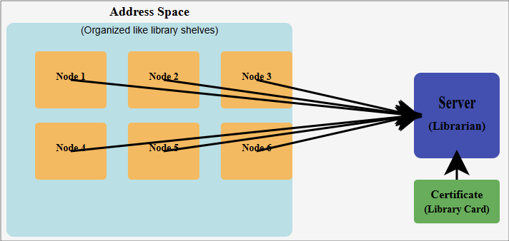
To make OPC UA easy to understand, consider it as a well-organized library:

The library (Address Space)

The server organizes all its data in a hierarchical structure called the Address Space.

Think of it like a library with shelves, folders, and files. Each client can browse this structure to find exactly what it needs.

The Books (Nodes)

Each piece of information is called a Node. Nodes can represent sensor readings, motor statuses, or even programs. Every node has a unique address, making it easy to locate and reference.

The Librarian (Server)

The server is like a librarian. When a client requests information, the server finds the data and delivers it in a standardized format.

The Library Card (Certificate)

Security is important. Before a client can access the server, it needs permission, similar to a library card.

Digital certificates verify the identity of both the client and the server, ensuring secure communication.

This model makes it easy to see why OPC UA is both powerful and user-friendly.

Why OPC UA is So Powerful

OPC UA offers several advantages over older communication standards:

Platform Independence

OPC UA works on Windows, Linux, and embedded devices. It is not limited to Microsoft technologies, which allows for greater flexibility in industrial environments.

Built-in Security

Unlike OPC Classic, where security was an afterthought, OPC UA includes encryption, authentication, and user access control from the ground up. This protects industrial systems from cyberattacks.

Information Modeling

OPC UA doesn’t just send raw numbers. It provides contextual information, making the data meaningful.

For instance, instead of sending “25.5,” it can send “Temperature: 25.5°C,” along with units, location, and timestamp.

Extensibility

OPC UA is designed to be future-proof. New features can be added without breaking existing systems, supporting innovation and long-term usability.

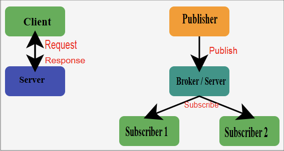
Dual Communication Models

Client/Server

The traditional request-response model. The client asks for data, and the server responds.

Publish/Subscribe

A more efficient model for many-to-many communication. Devices can publish their data, and multiple clients can subscribe to receive it. This reduces network load and improves responsiveness.

OPC UA and Industry 4.0

Industry 4.0 is the concept of smart, interconnected factories. It envisions a world where machines, systems, and humans work together seamlessly to optimize manufacturing processes. OPC UA plays a crucial role in making this possible.

Traditionally, factories used the “automation pyramid,” a rigid hierarchy where lower-level devices communicated only with their immediate supervisors.

OPC UA breaks this pyramid. It enables direct, secure communication across all levels, from sensors and actuators to cloud-based analytics.

Some applications enabled by OPC UA include:

Predictive Maintenance

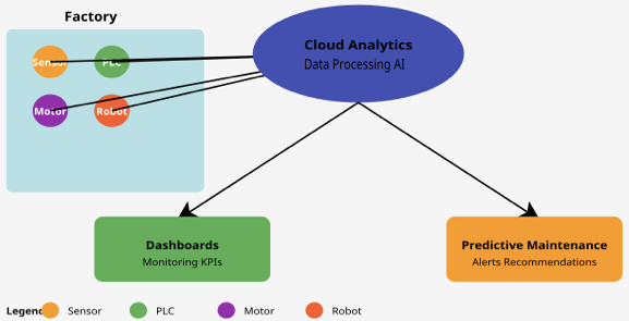
Machines can report their own health status. Advanced analytics can predict failures before they occur, reducing downtime and maintenance costs.

Remote Monitoring

Engineers can monitor machines from anywhere in the world, improving operational flexibility and response times.

Cloud Integration

Factory data can be sent to cloud platforms for advanced analytics, optimization, and AI-based decision-making.

Asset Management

OPC UA allows for automatic tracking of devices and systems, making inventory and maintenance management simpler and more accurate.

Real-World Example

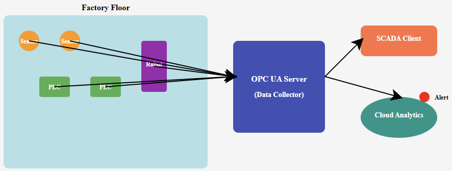
Consider a factory that produces automotive parts. Sensors monitor temperature, pressure, and vibration on critical machines. PLCs control conveyor belts and robotic arms.

With OPC UA, a single SCADA system can monitor all devices in real time. If a vibration sensor detects an abnormal condition, the system can automatically notify maintenance personnel, adjust machine operation, or log data for later analysis.

Without OPC UA, this would require multiple software drivers, custom scripts, and possibly manual intervention. With OPC UA, the process is streamlined, secure, and standardized.

Conclusion: The Future of Industrial Communication

OPC UA has transformed industrial communication. It replaced fragmented, insecure systems with a universal, standardized framework.

It is secure, flexible, and scalable making it ideal for IIoT and Industry 4.0 applications.

Its layered architecture ensures that it can evolve with technology. New devices, data types, and communication models can be integrated without breaking existing systems.

OPC UA allows factories to become smarter, more efficient, and more resilient.

For any organization looking to modernize its industrial operations, OPC UA is no longer optional—it is a key enabler of digital transformation.

FAQ:OPC UA Explained

Can OPC UA run on embedded devices?

Yes, it can run on small controllers, microcontrollers, and even IoT gateways.

How secure is OPC UA?

Security is built into its core, including encryption, authentication, and certificate-based access control.

What is the difference between OPC Classic and OPC UA?

OPC UA is platform-independent, secure, and capable of handling complex data. OPC Classic is Windows-based, less secure, and limited in flexibility.

Does OPC UA support real-time communication?

It supports near real-time communication using the Publish/Subscribe model, which is suitable for many industrial applications.

Can OPC UA integrate with cloud platforms?

Yes, OPC UA can send data to cloud analytics platforms for AI, predictive maintenance, and advanced monitoring.

    How Does an Ultrasonic Sensor Work?

    The rapidly evolving world of industrial automation, sensors play a critical role in bridging the gap between the physical and digital realms.

    From a robotic arm detecting the exact position of an object to conveyor belt ensuring accurate material flow. 

    Furthermore, an autonomous vehicle avoiding collisions. All this because the sensors are at the heart of decision-making.

    Among the many sensor technologies used for distance measurement and object detection, the ultrasonic sensors have proven to be a versatile and cost-effective solution.

    This article explains how ultrasonic sensors work, explores their applications in automation industrial, and provides their advantages and disadvantages.

    Furthermore, it compares ultrasonic sensors with other distance-sensing technologies.

    What Is an Ultrasonic Sensor?

    An ultrasonic sensor is a device that measures the distance to an object by using sound waves.

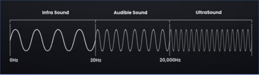
    This task is done at frequencies higher than the audible range of humans, which is above 20 kHz, as it can seen in the figure below.

    Infra – Ultrasound wave

    Most of industrial ultrasonic sensors operate between 25 kHz and 70 kHz, though some specialized ones can go higher.

    How does Ultrasonic Sensor Work?

    The principle is based on echo-location, similar to how bats and dolphins navigate:

    • The sensor emits a short ultrasonic pulse called trigger.
    • The sound wave travels through the air until it hits an object.
    • The wave reflects back to the sensor (echo).
    • The sensor calculates the time of flight (ToF) of the sound wave.

    From the information of the above, the following basic formula is deduced:

    The division by 2 accounts for the round trip (going to the object and returning).

    Working Principle in Automation World

    In an automation system, ultrasonic sensors typically consist of transducer, control circuit and the outputs:

    • Transducer: Is in charge of converting an electrical signal into ultrasonic sound waves and vice versa.
    • Control Circuit: Generates the pulse signal (trigger) and processes the received echo.
    • Output Stage: Provides an analog or digital output for the automation controller such as PLC, microcontroller, or industrial PC.

    Process Flow in Automation

    From an automation point of view, the whole process of ultrasonic measurement works as explained below

    • Triggering: The automation controller commands the sensor to emit a pulse.
    • Propagation: The sound wave travels at approximately 343 m/s in air.
    • Echo Detection: The sensor detects the reflected signal.
    • Signal Processing: The time difference between sending and receiving is converted into distance.
    • Decision Making: The automation system uses this distance data for tasks such as object positioning, counting, or safety control.

    Applications of Ultrasonic Sensors in Automation

    • Object Detection on Conveyor Belts: Detecting the presence or absence of packages and counting objects regardless of color or transparency.
    • Liquid Level Measurement: Monitoring tank levels in process industries (chemicals, food, water treatment).
    • Robotics and AGVs (Automated Guided Vehicles)
    • Collision avoidance and obstacle detection.
    • Packaging and Bottling Lines
    • Checking the fill level of bottles (especially transparent materials where optical sensors struggle).
    • Ensuring caps or lids are properly placed.
    • Automotive Automation: Parking assistance and blind-spot monitoring.
    • Industrial automotive robots using ultrasonic feedback.
    • People and Object Counting: Entry/exit monitoring in automated systems.
    • Smart building applications (lighting control, HVAC).

    Advantages (Pros) of Ultrasonic Sensors

    • Non-Contact Measurement & Simple Integration
    • No physical contact needed, avoiding wear and contamination.
    • Insensitive to Object Color and Transparency
    • Works equally well on shiny, transparent, or dark surfaces, unlike optical sensors.
    • Good Range Versatility: Can detect objects from a few centimeters to several meters away.
    • Cost-Effective: Cheaper than laser rangefinders or 3D vision systems.
    • Ruggedness: Can work in dusty, smoky, or poorly lit environments where cameras or IR sensors fail.
    • Provides analog (voltage/current) or digital (switching) outputs directly compatible with PLCs.

    Limitations (Cons) of Ultrasonic Sensors

    • Environmental Sensitivity: Sound speed changes with temperature, humidity, and air pressure, affecting accuracy.
    • Limited Resolution: Accuracy is typically within a few millimeters, not suitable for high-precision tasks.
    • Slow Response Time: Since sound travels slower than light, measurement cycle times are longer compared to laser or IR sensors.
    • Interference and Crosstalk: Multiple ultrasonic sensors operating close together can interfere with each other.
    • Angle Dependence: Works best when objects are perpendicular to the sensor. Slanted or sound-absorbing surfaces reduce detection reliability.

    Comparison with Other Distance Sensors

    In this chapter we address the comparison of our sensor in stud against other sensors that use the same technology

    Ultrasonic vs Infrared (IR) Sensors

    IR sensors use reflected infrared light to detect distance, but Ultrasonic works regardless of color or transparency, not affected by ambient light. Unfortunately, Ultrasonic have slower response and lower resolution 

    Ultrasonic vs Laser Rangefinders (LIDAR)

    Laser rangefinders measure distance using time of flight of light or phase shift, but Ultrasonic are cheaper, more rugged in dusty/dirty conditions. Although Ultrasonic have lower precision, shorter range, slower measurement.

    Ultrasonic vs Vision Systems (Cameras + AI)

    Vision systems provide rich data (shape, color, dimensions), while Ultrasonic are simple, inexpensive, and unaffected by lighting conditions.

    On the other hand, Ultrasonic provides only distance information, no shape or color recognition.

    Ultrasonic vs Capacitive/Inductive Proximity Sensors

    Capacitive sensors detect changes in dielectric properties; inductive sensors detect metal objects.

    On the other hand, Ultrasonic can detect any material (metal, plastic, glass, liquid). Although, Ultrasonic are larger size, slower response.

    Future of Ultrasonic Sensors in Automation

    With Industry 4.0 and IIoT (Industrial Internet of Things), ultrasonic sensors are evolving. Have started to include smart ultrasonic sensors with built-in temperature compensation to reduce environmental errors.

    Network connectivity (EtherCAT, IO-Link, Modbus) for seamless integration in smart factories.

    Process of miniaturization allowing their use in compact robotic systems. Also, hybrid sensing where ultrasonic sensors are combined with cameras or laser scanners for robust multi-sensor systems.

    Conclusion

    This article addressed about Ultrasonic sensors that use sound wave (echo-location) to obtain their measurement.

    It also showed the applications of the later sensor together with the advantages and disadvantages. 

    Furthermore, the comparison with other types of sensors was demonstrated as well as future of Ultrasound was discussed.

    After the above discussion, we can agree that Ultrasound sensors are one of the most versatile and cost-effective distance sensing solutions in industrial automation. 

    Their ability to detect objects regardless of color, transparency, or lighting conditions makes them indispensable in many applications, from conveyor belt monitoring to robotic navigation and liquid level measurement.

    However, like any technology, they come with limitations: slower response, lower accuracy compared to optical systems, and environmental dependencies. The choice of sensor ultimately depends on the specific automation requirement. 

    In many cases, ultrasonic sensors serve as the perfect balance between cost, reliability, and performance, particularly when paired with other sensor technologies.

     FAQ: How Does an Ultrasonic Sensor Work?

    What is an ultrasonic sensor?

    Ultrasound sensor is a device that is used to measure the distance. This sensor uses sound wave to detect how far the object is, just like bats and dolphins.

    How does it operate?

    It operates just like dolphin or bats, the send the wave and wait for it to reflect– back (echoing). Then they measure this delay time that is how they know how far is the object.

    What’s the distance calculation formula?

    Assume ToF is the that measure since the device send the wave until it echoed back, then
     

    4. What components are involved?

    It includes transducer, the component in charge of converting sound wave to electrical signal. A controller that processes the signal an send it to output.

    What are the advantages?

    Non-contact measurement, low coast, reliability, simple integration among others.

    Ladder Logic vs Function Block diagram vs Structured Text

    Programmable Logic Controllers (PLCs) are specialized computers used in industrial automation.

    In order for PLCs to run must have some instructions or programming languages inside their CPU.  

    The most famous languages like Ladder Logic (LD), Function Block Diagram (FBD), and Structured Text (ST) are under standard of International Electrotechnical Commission IEC-61131-3.

    This organization is in charge of defining standard of several programming languages for PLCs

    In this article we are going to see the foundation of each one, their advantages and disadvantages, and finally we will conclude by how to choose one. 

     Ladder Logic (LD)

    Ladder Logic is a graphical programming language that is the oldest and most widespread of the IEC 61131-3 standards. It was designed to resemble the electrical diagrams of relay-based control systems. 

    Structure of Ladder Logic

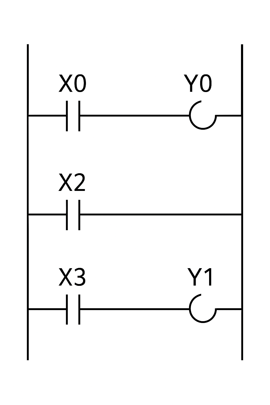
    The structure of Ladder Logic has two vertical bars representing the power line connected by horizontal “rungs” that contain the logic as shown in the figure below. 

    From the figure, the rungs are read from left to right and top to bottom. This simulates the physical flow of power through contacts (X) and coils (Y) to control output devices. 

    Structure of Ladder Logic

    Advantages of Ladder Logic

    Simple for beginners

    For fresh engineers, technicians and electricians, Ladder Logic is highly comfortable. 

    Easy Debugging

    Modern PLC software can animate Ladder Logic diagrams, highlighting active elements as the program runs. This provides real-time feedback, allowing you to quickly trace the logic flow.

    Ideal for Discrete Logic

    Ladder Diagram is highly effective for straightforward on/off control.

    Broad Familiarity

    With its long-standing use in industry, Ladder Diagram is the most widely adopted PLC language. 

    Disadvantages of Ladder Logic

    Data Handling Limitations

    Ladder Logic is not naturally designed for working with complex data types such as arrays or strings. 

    Low Portability

    Compared to Structured Text, Ladder Logic is harder to transfer between different PLC platforms.

    Differences in vendor-specific instructions and graphical layouts often mean programs must be rewritten from scratch.

    Complexity Management Issues

    Ladder Logic diagrams can become crowded with numerous rungs and intricate interconnections.

    This visual complexity makes large programs difficult to read, troubleshoot, and maintain.

    Weakness in Calculations

    LD is inefficient for advanced arithmetic, algorithms, or heavy data manipulation. Implementing such tasks typically produces bulky code that is harder to understand and less efficient than text-based approaches.

    Function Block Diagram (FDB)

    Function Block Diagram is a graphical language that represents the program as a network of interconnected blocks.

    Inside the block there may be other languages embedded such as Ladder Logic or any of the other PLC languages. 

    Structure of Function Block Diagram

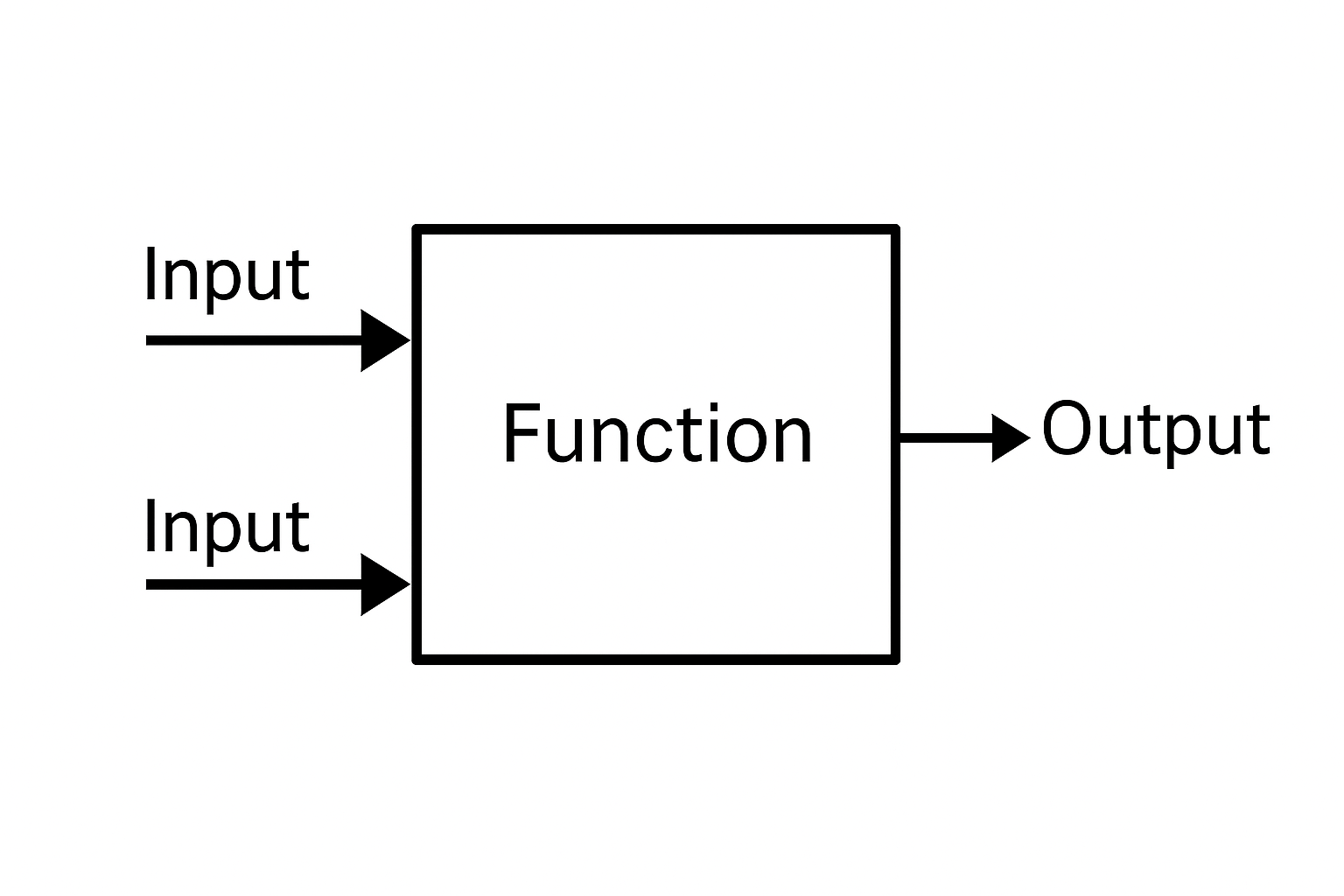
    The figure below illustrates the structure of the Function Block Diagram. Notice that the block named function could be performing any specific task, such as a timer, a counter, PWM block, a PID controller, or a custom-defined function. 

    Data and signals flow from the output of one block to the input of another, creating a clear visual representation of the program data flow.

    Structure of Function Block Diagram

    Advantages of Function Block Diagram

    Reusable Modular Design

    One of Function Block Diagram main advantages is its modular structure. Developers can build custom function blocks for specific tasks and reuse them across different programs or projects.

    Clear Troubleshooting

    FBD environments often provide animated data flow, making it easy to trace signals as they move between blocks.

    This visual feedback helps technicians quickly identify where a value is being created, modified, or interrupted.

    Language Flexibi