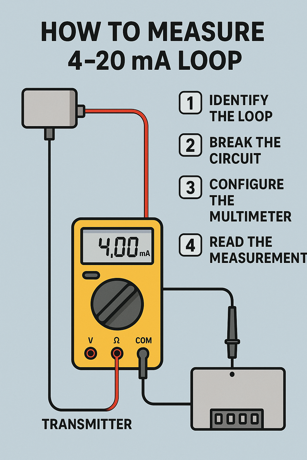
How to Measure a 4-20 mA loop Signal With a Multimeter

Process industries require monitoring of pressure, temperature, pH level, etc. for smooth operation.

These transmitters send information to PLCs or controllers on a 4 mA to 20mA loop.

Often engineers troubleshoot these transmitters by checking the 4 mA to 20 mA loop signal.

How the 4-20 mA loop works

The loop’s operation is straightforward: a sensor’s output voltage is first converted to a proportional current, with 4 mA normally representing the sensor’s zero-level output and 20 mA representing the sensor’s full-scale output. A reading of 20 mA means that a direct-acting valve, for example, is 100% open, and a reading of 4 mA means that it is closed. (The opposite is true for a reverse-acting valve). Readings between the maximum and minimum values indicate that the circuit is controlling the valve.

Verifying a 4-20 mA loop is a crucial step in both troubleshooting and calibrating process systems.

Full verification includes testing the output of the transmitter, the wiring, input to the control system and control system input card, and the return wiring back to the transmitter.

How to Measure a 4-20 mA loop Signal With a Multimeter

Here, I am going to show you two different methods on how to measure a 4-20 mA loop signal using a multimeter.

Method #1: Measure the 4-20 mA loop signal with the help of a multimeter

Identify the Loop Wiring

Find the two wires carrying the 4–20 mA signal from the transmitter or sensor to the controller/PLC.

Tip: Consult the device manual or wiring diagram.

Break the Circuit (Series Measurement)

Unlike measuring voltage (parallel), current measurement requires the multimeter to be inserted in series with the loop.

Choose a point where the loop can be safely opened (often at a terminal block or test point).

Power must remain ON in the loop for accurate measurement.

Configure the Multimeter

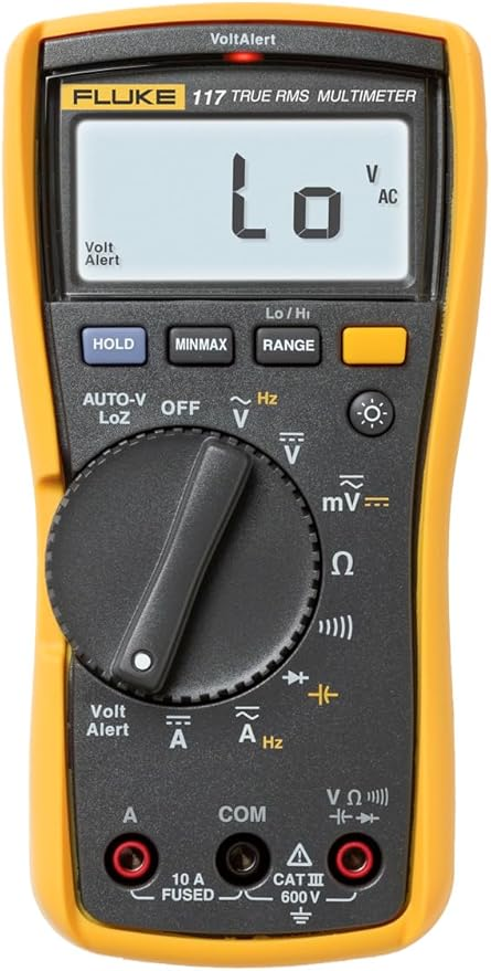
  • Turn the dial to DC mA (usually a 20 mA or 50 mA range is best).
  • Plug the red lead into the mA input jack (NOT the voltage or A high-current jack).
  • Plug the black lead into the COM jack.

Connect the Multimeter in Series

  • Disconnect one wire at the test point.
  • Connect the red lead to the wire coming from the transmitter.
  • Connect the black lead to the terminal going to the PLC/controller.
  • This way, the loop current flows through the meter.

Read the Measurement

A normal signal should read between 4.00 mA and 20.00 mA.

If you see:

  • <4 mA → Possible wiring issue, sensor fault, or calibration error.
  • >20 mA → Overrange condition or device malfunction.

Remove the Multimeter

Power down or hold the loop signal as needed.

Reconnect the wire directly to restore normal operation.

How to Measure a 4-20 mA loop Signal With a Multimeter

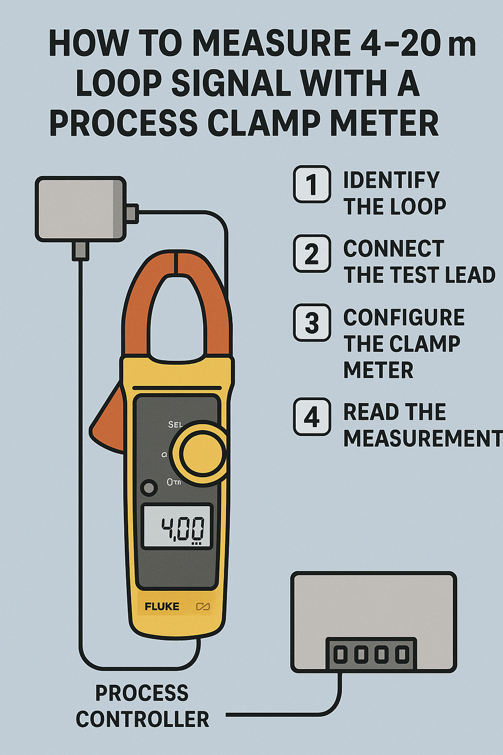
Method #2: Measure the 4-20 mA loop signal with the help of a process clamp meter

The functions of an advanced loop calibrator allow technicians to troubleshoot on the spot without disconnecting wires or “breaking the loop.”

Multifunction process calibrators can also be used to test 4-20 mA loops as well as digital controls.

Step 1: Access the wire connected to the ‘+’ terminal of the transmitter (no need to remove the wire).

Step 2: Put the process clamp meter in ‘Measure’ mode.

Step 3: Clamp the wire connected to the positive terminal of the transmitter and measure the mA signal as shown below.

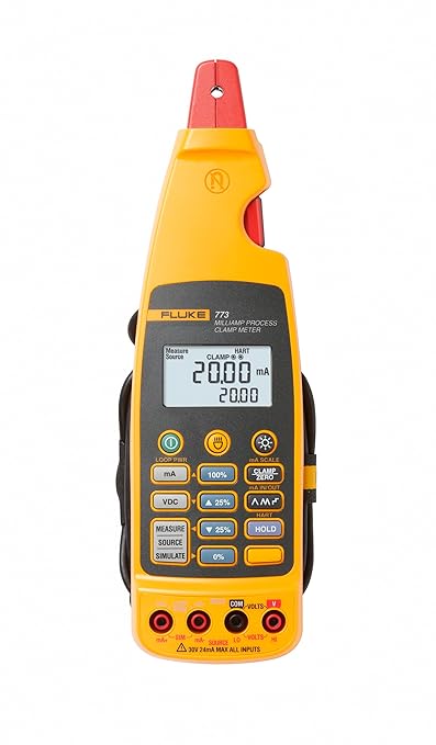
You can use Fluke’s 771 or 772 or 773 process clamp meters to measure mA without breaking the loop.

Advantage of this method

You need not break the loop to measure the mA signal. This is the biggest advantage.

Disadvantage of this method

Process clamp meters are expensive.

Safety Tips when using a multimeter to measure 4-20 mA loop

Check Multimeter Rating

Ensure the multimeter’s current rating is suitable for the expected measurement.

Proper Probe Insertion

Confirm that the multimeter probes are correctly inserted into the appropriate ports (usually labeled COM and mA/µA).

Avoid Overloading

Do not exceed the multimeter’s current measurement limit to prevent damage to the multimeter and ensure personal safety.

Conclusion

Measuring a 4-20 mA signal with a multimeter involves setting the multimeter to the appropriate mode, connecting it in series with the current loop, and interpreting the readings.

This process helps ensure that sensors and transmitters in industrial control systems are operating correctly.

Always prioritize safety by powering down the circuit before making connections and ensuring the multimeter is properly rated for the measurements being taken.

What Is a Multimeter? A Complete Guide for Beginners

A multimeter is a versatile electrical tool used to measure key properties of electricity, such as voltage, current, and resistance.

It’s also referred to as a volt-ohm meter or multi-tester and is essential for diagnosing electrical problems in circuits, batteries, and appliances.

Whether you’re an electrician, a technician, or a DIY enthusiast, a multimeter is a must-have tool for ensuring electronic components are functioning properly.

Types of Multimeters

Multimeters come in two main types:

Analog Multimeters

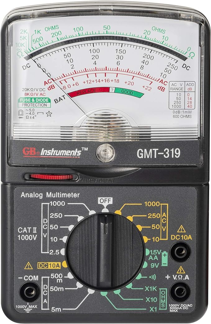
Analog Multimeters use a needle to display readings. These are particularly useful for observing fluctuating signals.

Digital Multimeters

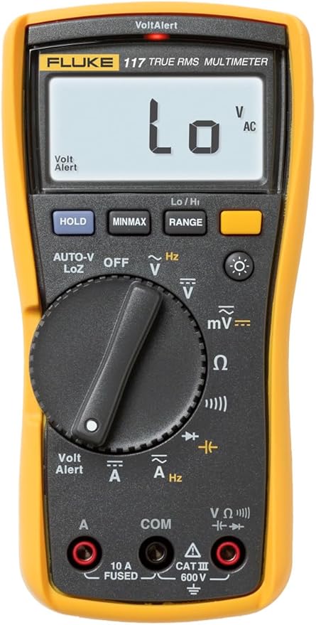
Digital Multimeters (DMMs) display numeric values on an LCD screen. They are more commonly used today due to their high precision, ease of use, and advanced features.

Key Functions of a Multimeter

A multimeter can measure:

AC Voltage (V~)

Alternating Current voltage is commonly used to test outlets and appliances.

DC Voltage (V–)

Most sensors and controllers use Direct Current (DC) voltage; also, you can find VDC in batteries and other direct current sources.

Current (A)

Measures the flow of electric charge, either in milliamps (mA) or amps (A).

Resistance (Ω)

Measures how much a component resists the flow of current.

Advanced digital models may also support additional functions like continuity testing, capacitance, temperature, frequency, and duty cycle measurements.

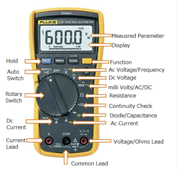
Multimeter Parts and Symbols

Understanding the parts of a multimeter helps you use it more effectively:

Display

Shows readings; either analog (needle) or digital (numbers).

Selector Knob

Used to choose what you’re measuring—voltage, current, resistance, etc.

Probes (Leads)

Two wires—black (common/ground) and red (positive)—used to test components.

Ports (Jacks):

  • COM (Common): Black probe goes here.
  • VΩmA: Red probe goes here for most measurements.
  • 10A or 300mA Jack: For high current measurements.

Common symbols include:

  • V~ or ACV: AC Voltage
  • V– or DCV: DC Voltage
  • A or mA: Current
  • Ω: Resistance
  • hFE: Transistor testing mode

Technical Characteristics of a Multimeter

When comparing multimeters, consider the following:

Resolution

This is the smallest change the multimeter can detect. Higher resolution is useful for precise readings.

Accuracy

An accuracy is the degree to which the measurement reflects the true value. Consumer-grade DMMs typically offer ±0.5% accuracy.

Input Impedance

Input impedance should be high to avoid altering the circuit under test. Most DMMs offer 1 MΩ to 10 MΩ.

Burden Voltage

The voltage drop caused by the multimeter when measuring current. Lower is better.

Practical Uses of a Multimeter

Multimeters are widely used for:

  • Testing batteries (e.g., checking if a battery is dead or charged).
  • Identifying live wires in AC outlets.
  • Diagnosing faulty components like resistors or capacitors.
  • Checking continuity in cables like coaxial or jumper wires.
  • Verifying power supply voltages in appliances or DIY electronics.
  • Detecting faulty chips or overheating on circuit boards.

How to Use a Multimeter

Here are the most common uses of a multimeter.

Testing Probes

Before using your multimeter, inspect it and the probes for physical damage. To test probe continuity:

  • Set to resistance (Ω).
  • Touch black and red tips together.
  • You should get a reading close to 0.5Ω. Replace probes if significantly higher.

How to measure AC Voltage with a multimeter

  • Turn the selector to AC voltage (V~).
  • Plug the black probe into COM and the red into VΩmA.
  • Insert probes into the wall outlet (black to neutral, red to hot).
  • Read the display, usually around 120V for standard US outlets.

How to measure DC Voltage with a multimeter

  • Set the knob to DC voltage (V–).
  • Insert probes into the corresponding jacks.
  • Touch the black probe to the negative terminal and the red to the positive.
  • Read voltage. For example, a 9V battery should show close to 9V.

Tip: If your digital multimeter reading is negative, switch the black and red probes for a positive reading. It should be the same number, but without a minus symbol.

Don’t mix up the positive and negative sides with an analog multimeter. It may damage the tool.

How to measure current with a multimeter

  • Set to the highest current range first.
  • Move the red probe to the 10A or 300mA jack, depending on the expected current.
  • Break the circuit and insert probes in series.
  • Read the current and adjust the range if needed.

How to measure resistance with a multimeter

  • Remove the component from the circuit.
  • Set to resistance (Ω).
  • Touch probes to either side of the component.
  • Adjust the range until a proper reading appears.

How to test transistor with a multimeter

  • Set the multimeter to hFE.
  • Insert transistor legs into the labeled hFE socket.
  • Compare the displayed gain to datasheet values.

Safety Tips When Using a Multimeter

  • Never touch metal parts of probes during live testing.
  • Set the correct range before measuring.
  • Start with the highest range, then step down.
  • Always disconnect power before testing resistance.
  • Store the multimeter and probes properly to prevent damage.
  • Remove batteries from the device if storing long-term.

How to chose the right multimeter

Now that you understand the basics, you can pick the right multimeter for your job. Both types measure DC voltage, AC voltage and resistance. However, they have different strengths and weaknesses.

Digital Multimeters

Digital multimeters are ideal for heavy day-to-day users. They’re also a smart investment for homeowners who want simple and clear readings. Basic models are less expensive than more complex ones.

Key features include:

  • Easy-to-read digital display
  • Auto-shutoff to save battery
  • Auto-ranging to simplify measurement
  • High reliability and precision

Analog Multimeters

Analog multimeters are more affordable. They’re a good fit for DIYers who only need one occasionally. Avoid dropping an analog multimeter, as the impact can damage it.

These multimeters are known for these characteristics:

  • Cost-effectiveness
  • Taking longer to dial in a measurement
  • Measuring amps well, especially milliamps.

FAQ: What Is a Multimeter?

What is a multimeter used for?

A multimeter is used to measure electrical values like voltage, current, and resistance. It helps diagnose problems in outlets, batteries, appliances, circuit boards, and electronic components.

Can I use a multimeter to test a battery?

Yes. Set your multimeter to DC voltage, connect the probes to the battery terminals, and compare the reading to the battery’s rated voltage. This tells you if the battery is charged, low, or dead.

What is the difference between analog and digital multimeters?

Analog multimeters use a needle to show readings and are better for monitoring rapidly changing signals.

Digital multimeters provide precise numeric readings on a screen and are more common due to their accuracy and ease of use.

How do I measure resistance with a multimeter?

Set the multimeter to the resistance (Ω) function, disconnect the component from power, and place the probes on each side of the resistor. The display will show the resistance value.

Can a multimeter test AC and DC voltage?

Yes, most multimeters can test both. Use the V~ setting for AC voltage and V– for DC voltage. Always start at a higher range and work your way down for safety.

What are the common symbols on a multimeter?

  • V~: AC voltage
  • V–: DC voltage
  • A or mA: Current (amps or milliamps)
  • Ω: Resistance
  • hFE: Transistor gain

Is it safe to use a multimeter on a live circuit?

Yes, if used properly. Always hold the probes by their insulated grips, never touch the metal tips, and use a multimeter rated for the voltage range you’re testing.

For high-voltage mains, use Category II or higher-rated meters and consider calling a professional.

Why is my multimeter reading “1” or “OL”?

This means the resistance is too high for the current range setting. Try adjusting the range down until the multimeter provides a readable value.

How do I test continuity with a multimeter?

Set your multimeter to the continuity or resistance setting (often with a sound wave symbol).

Touch the probes to both ends of the wire or component. A beep or near-zero reading indicates good continuity.

How do I choose the right multimeter?

For basic use, a digital multimeter with auto-ranging and clear display is recommended. For occasional or budget use, analog models may suffice. Consider features like accuracy, resolution, and safety ratings when choosing.

Key Takeaways: What is a multimeter?

A multimeter is a powerful tool that combines multiple functions into one handheld device.

Whether you’re checking an old wall socket, verifying a car battery, or troubleshooting an electronic board, a multimeter provides the data you need to diagnose and fix problems with confidence.

By understanding its components, measurement types, and safety precautions, you can use a multimeter effectively and safely across a wide range of electrical tasks.

What is an End of Line Resistor?

End-of-line resistors (EOL resistors) play a critical role in the reliability and integrity of fire alarm systems, security systems, and other monitoring circuits.

Although they may seem like a small component, their function is essential for detecting faults and maintaining safety.

What is an End of Line Resistor?

An end-of-line resistor (EOL resistor) is a resistor installed at the end of a circuit to monitor the integrity of wiring in security, fire alarm, or signaling systems.

It provides a specific resistance value that is recognized by the control panel to confirm that the wiring is intact and the circuit is properly terminated.

EOL resistors are passive electrical components and are typically placed at the last device in a looped (supervised) circuit.

Applications of End-of-Line Resistors

EOL resistors are commonly used in the following systems:

Fire Alarm Systems
To monitor for open or short circuits in detection zones.

Intrusion Detection / Burglar Alarms
Installed in zones (door/window contacts, motion detectors) to monitor tampering or disconnection.

Emergency Notification Systems
Used to supervise audio or visual alert wiring.

Industrial Automation
To maintain the integrity of monitoring circuits for safety-critical processes.

In all these applications, the EOL resistor helps ensure that the system is not only working but also capable of detecting any faults in wiring or tampering with devices.

Why Are End-of-Line Resistors Used?

Here are the key reasons EOL resistors are implemented in supervised systems:

Circuit Integrity Check
The control panel continuously checks the resistance at the end of the circuit. If the resistor is missing, shorted, or replaced with an incorrect value, the panel will trigger a trouble or fault condition.

Tamper Detection
Prevents bypassing security sensors or alarm contacts. If someone tries to short or cut the wires, the panel will notice the change in resistance and respond accordingly.

Safety and Compliance
EOL resistors are required in most commercial fire and security systems by NFPA and UL standards to ensure safety and system readiness.

Troubleshooting Aid
Makes it easier for technicians to quickly detect line faults during installation or maintenance.

    How to Select the Right End-of-Line Resistor

    Choosing the right EOL resistor depends on the system design and control panel specifications. Here’s what you need to consider:

    Resistance Value (Ohms)

    • The most critical factor.
    • Common values: 1kΩ, 2.2kΩ, 4.7kΩ, 5.6kΩ, 10kΩ, etc.
    • Always match the value recommended by the manufacturer of the control panel.

    Wattage Rating

    • Typically low (1/4 watt or 1/2 watt).
    • For most alarm and fire circuits, 1/4 W is sufficient due to low current.

    Tolerance

    • ±5% is usually acceptable.
    • For highly sensitive circuits, a tighter tolerance (e.g., ±1%) may be required.

    Physical Size and Form

    • Through-hole (leaded resistors) are common.
    • Some applications may use surface-mount resistors.

    Environmental Considerations

    For harsh environments, consider resistors with protective coating or rated for high temperature and humidity.

    Practical tip: Never guess the resistor value. Refer to the system manual or panel datasheet before installation.

    How It Works in a Fire Alarm Zone

    Let’s say a fire alarm zone requires a 4.7 kΩ EOL resistor. Here’s how it works:

    When everything is correctly wired, the control panel sees 4.7 kΩ at the end of the circuit → Normal condition.

    • If someone cuts the wire or removes the resistor → Open circuit detected → Trouble signal.
    • If someone shorts the wires → Zero resistance detected → Trouble or Tamper alert.

    This monitoring ensures the fire alarm system will operate properly in case of an emergency.

    FAQ: What is an End-of-Line Resistor?

    What happens if I don’t install an end-of-line resistor?

    The system will likely show a trouble condition, and in many cases, the zone won’t function properly. EOL resistors are essential for proper supervision.

    Can I use any resistor value as an EOL resistor?

    No. You must use the exact value specified by the control panel manufacturer. Using an incorrect resistor will result in false alarms or circuit faults.

    Where exactly should I place the EOL resistor?

    It should be installed at the last device in the zone wiring, not at the control panel. This allows full supervision of the entire circuit length.

    Can I install multiple EOL resistors in parallel?

    Generally, no—only one EOL resistor per supervised zone is allowed unless the system design specifically permits parallel resistors. Adding more can alter resistance values and confuse the panel.

    Are EOL resistors reusable?

    Technically yes, but it’s best to use a new resistor each time you rewire a system to ensure integrity and avoid damage from previous use.

    How do I test an end-of-line resistor?

    Use a digital multimeter set to the resistance (Ω) mode. Disconnect one side of the resistor and measure its resistance across both leads. Compare to the expected value.

    Key Takeaways: What is an End-of-Line Resistor?

    End-of-line resistors are small but powerful components that play a major role in supervising alarm and control circuits.

    Whether you’re installing a fire alarm, a security system, or any supervised loop, selecting and placing the correct EOL resistor ensures your system is safe, secure, and up to code.

    If you’re setting up or maintaining a system, don’t overlook the EOL resistor, it could be the difference between detecting a fault or missing a critical failure.

    How To Select The Best Smoke Detector For You

    In today’s fast-paced world, ensuring the safety of our homes has never been more important. One of the most critical components of a robust home safety system is the smoke detector.

    These devices serve as our first line of defense against the dangers of fire, providing early warnings that can save lives and protect property.

    With a myriad of options available in the market, choosing the right smoke detector can be a daunting task.

    What Are The Types of Smoke Detectors?

    When it comes to safeguarding your home, understanding the different types of smoke detectors is essential.

    Each type uses distinct technology to detect smoke and fire, and knowing the differences can help you choose the best one for your needs.

    Here’s a detailed look at ionization, photoelectric, and combination smoke detectors.

    Ionization Smoke Detectors

    Ionization smoke detectors are highly effective at detecting fast-flaming fires. They work by using a small amount of radioactive material placed between two electrically charged plates, which ionizes the air and creates a current between the plates.

    When smoke enters the chamber, it disrupts the flow of ions, reducing the current and triggering the alarm.

    These detectors are particularly sensitive to the smaller particles produced by fast-burning fires, such as those caused by paper or flammable liquids.

    However, they are prone to false alarms from everyday activities like cooking or steam from showers.

    Pros

    • Quick detection of fast-flaming fires
    • Generally less expensive than photoelectric detectors
    • Widely available and easy to install

    Cons

    • More prone to false alarms from non-fire sources
    • Less effective at detecting smoldering fires

    Photoelectric Smoke Detectors

    Photoelectric smoke detectors are designed to detect smoldering fires more effectively. These fires typically produce larger smoke particles, which photoelectric detectors are particularly sensitive to.

    The device uses a light source and a light sensor placed at an angle in a sensing chamber. When smoke enters the chamber, it scatters the light, which then hits the sensor and triggers the alarm.

    This technology makes photoelectric detectors less likely to give false alarms from cooking or steam.

    Pros

    • Quick detection of smoldering fires
    • Less prone to false alarms from cooking or steam
    • Effective at detecting larger smoke particles

    Cons

    • Generally more expensive than ionization detectors
    • Might not detect fast-flaming fires as quickly

    Combination Smoke Detectors

    Combination smoke detectors, as the name suggests, use both ionization and photoelectric technologies to offer comprehensive protection.

    By incorporating the strengths of both types, combination detectors can effectively detect both fast-flaming and smoldering fires.

    These detectors are designed to reduce the number of false alarms while providing a broader range of fire detection capabilities.

    They are ideal for homeowners who want the best of both worlds without having to install multiple units.

    Pros

    • Comprehensive protection against both fast-flaming and smoldering fires
    • Reduced number of false alarms
    • Convenient and cost-effective solution

    Cons

    • More expensive than single-technology detectors
    • May require more maintenance due to the dual-sensing technology

    Each type of smoke detector has its strengths and weaknesses, and the best choice for your home depends on your specific needs and circumstances.

    Ionization detectors are great for detecting fast-flaming fires, while photoelectric detectors excel at catching smoldering fires.

    Combination detectors provide the most comprehensive protection, though they come at a higher price point.

    By understanding how each type works and their respective advantages, you can make an informed decision to ensure your home is well-protected against fire hazards.

    Key Features to Consider When Selecting The Best Smoke Detector

    When selecting a smoke detector, understanding its key features can make a significant difference in ensuring the safety of your home.

    Here, we delve into four critical aspects: sensitivity, response time, battery life, and the false alarm rate. These elements are essential in evaluating the overall effectiveness and reliability of a smoke detector.

    Sensitivity

    The sensitivity of a smoke detector refers to its ability to detect smoke particles in the air. A highly sensitive smoke detector will quickly pick up on the presence of smoke, even if it is minimal.

    This feature is crucial for early detection, giving occupants more time to evacuate and reducing the risk of damage and injury.

    Sensitivity levels can vary between different types of smoke detectors—ionization models are generally more sensitive to fast-flaming fires, while photoelectric detectors are better at detecting smoldering fires with larger smoke particles.

    When choosing a smoke detector, consider the environment in which it will be installed. For areas like kitchens or bathrooms, where smoke and steam are common, a less sensitive model might be preferable to reduce false alarms.

    Response Time

    Response time is the duration it takes for a smoke detector to react and sound an alarm once smoke is detected.

    This feature is paramount because a faster response can mean the difference between a contained fire and a catastrophic one.

    Ionization smoke detectors tend to have quicker response times to flaming fires, while photoelectric detectors respond more rapidly to smoldering fires.

    Combination detectors aim to balance these response times, providing quick alerts for both types of fires. A smoke detector’s response time is also influenced by its placement within a home.

    For instance, installing detectors in strategic locations, such as near bedrooms and on every level of a house, can ensure that an alarm is heard promptly.

    Battery Life

    Battery life is a critical factor in the reliability of smoke detectors. Smoke detectors typically use either replaceable batteries or long-life sealed lithium batteries.

    Units with replaceable batteries require regular maintenance to ensure they remain operational, usually every six months to a year.

    Long-life sealed lithium batteries can last up to ten years, aligning with the typical lifespan of the smoke detector itself.

    Hardwired smoke detectors often have battery backups to maintain functionality during power outages.

    Regularly testing your smoke detectors and replacing batteries as recommended is essential for consistent performance.

    Opting for a smoke detector with a long-lasting battery can reduce maintenance efforts and ensure continuous protection.

    False Alarm Rate

    The false alarm rate refers to how often a smoke detector sounds an alarm without a genuine fire hazard.

    Frequent false alarms can be a significant inconvenience, leading to the temptation to disable the alarm, which poses a safety risk.

    Factors such as cooking, steam from showers, or even dust can trigger false alarms in some detectors.

    Photoelectric smoke detectors are generally less prone to false alarms caused by cooking and steam, while ionization detectors might be more susceptible.

    Many modern smoke detectors include features like hush buttons or smart technology that allows temporary silencing of false alarms.

    When selecting a smoke detector, it’s crucial to consider the environment and choose a model with a low false alarm rate to ensure that any alarm is taken seriously.

    FAQ: Best Smoke Detectors

    What type of smoke detector is best?

    The best type of smoke detector depends on the specific needs and environment of your home. There are three main types of smoke detectors: ionization, photoelectric, and dual-sensor.

    • Ionization Smoke Detectors: These are generally more responsive to fast-flaming fires but may be prone to false alarms from cooking smoke or steam.
    • Photoelectric Smoke Detectors: These are better at detecting slow-smoldering fires, which produce a lot of smoke before bursting into flames, and are less likely to cause false alarms.
    • Dual-Sensor Smoke Detectors: These combine both ionization and photoelectric sensors, providing comprehensive detection for both types of fires. For optimal safety, a dual-sensor model is often recommended.

    What is the best-recommended smoke alarm?

    The Kidde Smoke & Carbon Monoxide Detector is highly recommended due to its dual detection capabilities, combining both smoke and carbon monoxide sensors.

    It features advanced sensing technology to reduce false alarms and includes a 10-year built-in lithium battery for continuous protection.

    The clear voice alerts and easy installation process add to its appeal, making it a top choice among users.

    Which is better, First Alert or Kidde?

    Both First Alert and Kidde are reputable brands in the smoke detector market, each with its own strengths.

    • First Alert: Known for its reliability and comprehensive range of models, First Alert smoke detectors often feature advanced technology and are highly rated for their durability and ease of use.
    • Kidde: Kidde smoke detectors are praised for their innovative features, such as voice alerts and dual smoke and carbon monoxide detection. They also tend to be user-friendly and come with long-lasting batteries.

    Choosing between the two often comes down to specific preferences and needs, such as whether you prefer a voice alert system or a model with dual detection capabilities.

    What is the best technology for smoke detectors?

    The best technology for smoke detectors is often the dual-sensor technology, which incorporates both ionization and photoelectric sensors.

    This ensures comprehensive detection of both fast-flaming and slow-smoldering fires, offering the highest level of safety.

    Additionally, integrating carbon monoxide detection into a smoke alarm adds another layer of protection, especially in preventing carbon monoxide poisoning.

    How often should smoke detectors be replaced?

    Smoke detectors should generally be replaced every 10 years. Over time, the sensors can become less sensitive, reducing their effectiveness.

    It’s important to check the manufacturer’s recommendations and ensure regular maintenance and testing to keep the detectors in optimal working condition.

    Where should smoke detectors be installed?

    Smoke detectors should be installed on every level of your home, including the basement and inside each bedroom. They should also be placed outside sleeping areas and in hallways.

    It’s recommended to avoid installing them near kitchens or bathrooms to prevent false alarms caused by steam or cooking smoke.

    For the best protection, refer to the guidelines provided by the National Fire Protection Association (NFPA) and your local building codes.

    Key Takeaways: How to select the best smoke detector for you

    When choosing a smoke alarm, consider the specific needs of your home environment, including the type of fires most likely to occur, ease of installation, and long-term maintenance.

    With this comprehensive comparison, you can confidently select the smoke alarm that best ensures the safety of your home and loved ones.

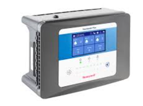
    Wireless Gas Detection System

    In more than 5 years in gas detection systems, I helped customers design different gas detection systems, and one of them is the wireless gas detection system.

    What I found out is that most customers prefer portable or fixed gas detectors and are usually skeptical when it comes to shifting to wireless.

    In this post, I will explain the wireless gas detection system, what it is, the benefits, and some drawbacks of this gas detection system.

    What is a gas detection system?

    A gas detection system detects potentially harmful gases. For example, H₂S can be a life threat to organic compounds, humans, and animals.

    Most gas detectors are portable, but some applications require wireless gas detection.

    What are wireless gas detectors?

    Wireless gas detectors and wireless gas monitors are designed to monitor toxic and combustible gases in the air continuously. 

    Due to its wireless nature, no complex system configuration is needed. Your job is complete once you assign a unique address to the wireless gas monitor or detector.

    The wireless gas detection system will collect all the necessary data information from the sensor, including the target gas type. 

    Historical data logging and RTU communication for PLC and DCS systems are available onboard.

    Importance of Wireless gas detection systems

    Rapidly deployable and fully flexible, wireless gas detection systems provide a solution that is as consistently safe and reliable as fixed gas detection networks. 

    Operating as a stand-alone or backup post-incident wireless gas detection solution ensures continued monitoring when traditional systems fail.

    Wireless gas detection systems are ideal for established and new-build plants, mines and tunnels, rapidly changing developments, or where you are expanding your operation beyond your initial scope.

    Benefits of the wireless gas detection system

    Reduced Installation cost

    Wireless gas detection systems do not use cables, which will massively reduce the installation cost. This includes the cost of buying the cables, transporting them to your facility, and installing them.

    No more expensive cables and underground cable conduits.

    No troubleshooting on the cables

    One of the main issues of the wired gas detection system is troubleshooting when you do not get the desired signal.

    You will need a multimeter and have to troubleshoot different parts of the installation. This will take a lot of time, and you might need to pay another company to do the job.

    This issue is not present with wireless systems. Most wireless systems I worked with have an auto-diagnostic feature that detects connection issues and sends an alarm. 

    Damage to one unit will not lead to the destruction of the whole system

    I worked on the wired systems for a long time. One issue I had is if you use Modbus RTU, for example, and have many sensors wired in a daisy chain. And accidentally, if one of the sensors has an open circuit, the whole bunch of sensors will fail to communicate.

    We do not have this problem in the wireless gas detection systems; if one sensor goes bad, it will remove itself from the network, and the rest will continue communicating without any problem.

    Easily add more sensors to the existing wireless network

    Adding new sensors to a wired system can be complicated. There are many things to consider, such as the cable length, power drop, power sources, etc.

    In the wireless gas detection system, adding a new sensor is simple. For example, if you use a mesh wireless network, you must set a network ID and a unique PAN ID and press join the network.

    No complicated system configurations

    Wireless gas detection systems are very easy to configure. They usually do not require complicated training and have an intuitive configuration panel.

    Application of wireless gas detectors

    Wireless gas detectors can be used in a lot of environments. Some of the applications of wireless gas detectors include:

    • Tank forms
    • Refineries
    • Chemical storage
    • Water & wastewater treatment
    • Drilling rigs
    • Offshore platforms

    Do you use a wireless gas detection system at your company? If yes, let us know the challenges and benefits you have seen up to now, and if not, let us know if you’re thinking about implementing one and how we can help.

    Fixed Gas Detectors

    Fixed gas detectors are used to protect a facility in a single area and act as an early warning indicator of high gas levels or leaks.

    These detectors are designed to alert workers of the potential danger of poisoning by toxic gas exposure, asphyxiation due to lack of oxygen, or explosion caused by combustible gases.

    What is a fixed gas detector?

    A fixed gas detector is a safeguarding system that constantly monitors a location due to the excess levels of gases. 

    Unlike portable detectors, fixed detection devices make it possible to secure an entire area 24 hours a day.

    They can also be connected to a detection system, which displays the gas concentration in numerical value, and then triggers the servo-controls in the event of an abnormal value.

    Is a fixed gas detection system necessary?

    Yes, a Fixed gas detection system is necessary as it is often required to protect facilities by the insurance companies that underwrite them and even by some standard electric codes.

    It can alert potential danger before it occurs

    Fixed detectors are used to detect an abnormal or dangerous presence of gas in a specific area and to warn the user in the event of potential hazards.

    Equipped with sensors (called cells), they can measure the concentration of one or more types of gas, depending on the model. 

    It will protect your facilities 24/7

    Unlike portable detectors, fixed detection devices make it possible to secure an entire area 24 hours a day.

    They can also be connected to a detection system, which displays the gas concentration in numerical value, and then triggers the servo-controls in the event of an abnormal value.

    It can be connected with other security systems

    Fixed gas detectors can easily be connected with other security systems like fire suppression systems, smoke detection systems, etc, to one control panel and help to simplify the control of your facility.

    It is required by law

    OSHA, NIOSH, NFPA, and other government agencies will want you to have some kind of a fixed gas detection system in certain facilities.

    What are the Components of a Fixed Gas Detection System?

    A fixed gas detection system consists of 3 parts: the sensor, transmitter, and controller.

    The sensor

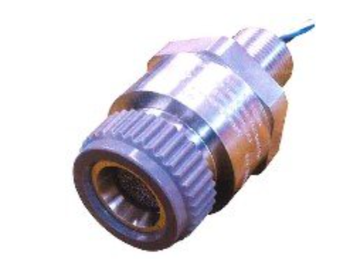
    The sensor is the actual device that senses the gas. Many sensors, such as catalytic beads, infrared, and electrochemical, are used in gas detection.

    Sensors typically last 2 to 4 years but can last longer or shorter depending on the application’s nature.

    Solid-state and infrared sensors typically last much longer, and it is not uncommon for them to last 5 to 10 years or more.

    Most fixed sensors can work as standalone units, but it is better to connect them to a transmitter and a controller if you want to integrate them with other systems.

    The Transmitter

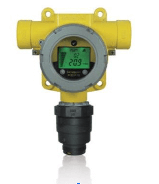
    Most sensors require a transmitter to amplify the signal and convert the gas sensor signals into a standardized output, such as 4-20 mA, Modbus, and HART, for transmitting the signal to a controller.

    The transmitter is usually close to the sensor, and zero and span adjustments must be done at the transmitter.

    Most transmitters are operated from 24 VDC and utilize 2 or 3 wires. In general, even if a sensor can be used without a transmitter, the use of a transmitter is often preferred for distances over 300’ to 500’ to simplify the calibration effort.

    In general, even if a sensor can be used without a transmitter, a transmitter is often preferred for distances of 300’ to 500’ to simplify the calibration effort.

    The Controller

    The controller is the device that receives and interprets the signals from the sensors and sensors/transmitters.

    The controller typically provides a readout of the gas concentration, audible and visual alarms for dangerous gas levels, and general alarm relays for activating an external alarm or other action.

    In some applications, it is preferred to send the transmitter signal (such as 4-20 mA) directly into a

    PLC (Programmable Logic Controller) or other similar control devices. In this case, the PLC activates the alarm conditions and relays, and a “Gas Detection” controller is not necessary.

    What is the best mounting height for fixed gas detectors?

    This is one of the questions I get most of the time. In my experience, the mounting height at which a fixed sensor should be mounted depends on the density of the gas it monitors relative to the air.

    Heavier than air

    Gases that are heavier than air will tend to sink to the floor and concentrate there; my recommendation for the sensors that detect these types of gases is to mount them 1 to 3 feet from the floor.

    Lighter than air

    Gases like hydrogen and methane are lighter than air, which means the gases will rise and concentrate near the roof.

    If you have a fixed gas detector to measure any gas that is lighter than air, you need to mount the sensors 1 to 3 feet from the ceiling.

    Similar to air

    Gases that have a relative density similar to air will be floating in the air near the breathing zone. Mount sensors in the breathing zone, which is 4–6 feet above the floor. 

    If you do not know if the gas in question is heavier, lighter, or similar to air, you can google the relative density of that gas; if it is above 1, it means it is heavier than air; if it is less than 1, it means it is lighter than air; and if it is about 1, it means it is the same as air.

    Tips for mounting fixed gas detectors

    • Place sensors near the source of the gas, like piping or a compressor. 
    • Mount sensors in areas with good air circulation, but not in areas with rapidly moving air. 
    • Avoid mounting sensors near room entrances, fresh air intake vents, or vehicle/generator exhaust points. 
    • Mount sensors upright on a vertical surface, like a wall, beam, or column. 
    • Consider how accessible the sensor is for calibration and maintenance. 
    • If you have a separate display from the sensor, mount it where it’s easy to read

    FAQ: Fixed Gas Detection System

    What is the difference between fixed and portable gas detectors?

    Fixed Gas Detectors: Ideal for continuously monitoring specific areas or zones within facilities where gas hazards are present.

    Portable Gas Detectors: Suitable for applications requiring mobility, such as confined space entry, leak detection, maintenance activities, or outdoor monitoring.

    What are the two types of gas detection systems?

    Gas detectors come packaged in two main form factors: portable devices and fixed gas detectors.

    Final words

    That is it. Those are the three main components of a fixed gas detection system. Thank you for reading.

    What Is Industrial Automation?

    Industrial automation is the use of computer‑based control systems, or sometimes even analog ones. It’s about letting machines manage themselves with minimal human intervention.
    It involves using machines, robots, and software to perform tasks that usually back then were performed by humans.

    Core Components & How It Works

    At the core of industrial automation systems are devices and technologies that monitor, control, and execute tasks, replacing or reducing the need for human intervention.

    This includes hardware like PLCs (Programmable Logic Controllers), sensors, actuators, robotic arms, HMIs (Human-Machine Interfaces), and software systems such as SCADA (Supervisory Control and Data Acquisition) and DCS (Distributed Control Systems).

    PLCs are industrial-grade computers that take input from sensors (suc