What is a Variable Frequency Inverter?

A Variable Frequency Inverter (VFI), also called a Variable Frequency Drive (VFD), is a device that controls how fast an AC motor runs. It does this by changing the frequency and voltage of the electricity going to the motor.

Unlike basic controllers that just turn a motor on or off, a VFI lets you set the speed to match your needs. This makes machines run more efficiently, improves process control, and reduces wear on parts.

In simple terms, a VFI converts AC power to DC, then back to AC again, but at a different frequency and voltage.

This article details what a VFI is, how does it work, the benefit of using it, the common applications and the trending future.

The History of Motor Control

Before VFIs existed, motors had only two states: ON or OFF. It was like driving a car that could only go full speed or stop.

In factories, this wasted a lot of energy because machines often didn’t need full speed.

Older systems used belts or gears to slow things down, but these were bulky and inefficient. Then in the mid 1900s, Engineers, including Vladimir G. Lukyanov, helped pioneer early variable-speed systems. 

As powerelectronics advanced, new components like the IGBT (Insulated-Gate Bipolar Transistor) made VFIs practical and reliable.

The first commercial model appeared in 1967, and since then, VFIs have become essential in modern industries.


How a Variable Frequency Inverter Works


A Variable Frequency Inverter controls motor speed through three main stages, the rectifier, the DC bus, and the inverter.

Rectifier Stage

The rectifier is the first part. It converts incoming AC power to DC power using diodes.
These act like one-way gates, letting current flow in only one direction. The output is a pulsatingDC waveform. The following figure shows the rectifier stage of a VFI.

What is a Variable Frequency Inverter?

DC Bus Stage

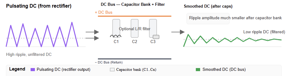
Next comes the DCbus, which smooths out that pulsating current. Large capacitors act as filters to create steady DC voltage.

This stable energy is then sent to the inverter. The figure below illustrates the DC bus stage of a VFI.

Inverter Stage

Finally, the inverter converts the steady DC back to AC—but with a variable frequencyand voltage.

It uses high-speed switches called IGBTs that turn on and off rapidly in a pattern called Pulse Width Modulation (PWM).

By adjusting the timing of these pulses, the VFI creates a new AC output that controls the motor’s speed precisely. The next figure indicates the inverter stage of a VFI.

Relationship between Frequency, Voltage, and Speed

The speed of an AC motor is directly proportional to the frequency of the power supplied to it. This is governed by the formula:

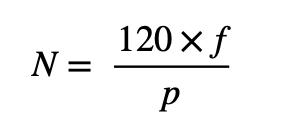
Where:

N = Speed in revolution per minute (RPM)

F = Frequency in Hertz (Hz)

P = Number of motor poles


By controlling fre frequency (f), the VFI can precisely control the motor’s speed (N). To maintain a stable magnetic field and prevent motor overheating, the VFI also proportionally adjusts the voltage supplied to the motor. This is known as the Volts-per-Hertz (V/Hz) ratio.

Benefits of Using a VFI

Energy Efficiency and Cost Savings

VFIs save energy by letting motors run only as fast as needed. For fans and pumps, even a small speed reduction can cut energy use dramatically.

For example, reducing motor speed by 20% can save about 50%ofenergy. This help to lower electricity bills and helps the environment.

Better Process Control

With a VFI, you can control how fast a motor speeds up, slows down, or runs. This is vital in manufacturing and conveyor systems, where smooth, precise motion ensures quality and prevents damage.

Longer Equipment Life

The soft-start and soft-stop capabilities of a VFI protect the motor and associated mechanical components from the stress of a sudden full-voltage start. This controlled acceleration and deceleration reduces mechanical wear.

The latter is common present on gears, couplings, and belts. So, if prevented it help to extend the lifespan of the equipment.

It also reduces the need for maintenance and minimizes unscheduled downtime.

Built-in Protection

VFIs come with built-in protection features. These features help to protect motors from problems like overvoltage, undervoltage, and overheating. These safety features also help to avoid costly breakdowns.

Common Applications of VFIs

VFIs are used across a different array of industries and applications. Here under are briefly explained:

HVAC systems

In heating, ventilation, and air conditioning systems, VFIs are used to control the speed of fans, pumps, and compressors.

This allows the system to adjust airflow and water flow based on real-time demand. 

This significantly reduces energy consumption compared to systems that run at a constant speed.

Water and wastewater management

VFIs are essential for controlling the pumps in water treatment plants and municipal water systems.

By optimizing flow and pressure, VFIs not only save energy but also prevent pressure surges, a phenomenon known as water hammer, which can damage pipes.

Industrial fans and pumps

Industrial processes often require large fans and pumps that have varying load requirements. VFIs allow these systems to operate at optimal efficiency, reducing energy waste.

Conveyor systems

In material handling, VFIs provide smooth, controlled acceleration and deceleration of conveyor belts.

This protects products and mechanical components, leading to higher efficiency and reduced maintenance.

Elevators and escalators

VFIs ensure smooth and safe acceleration and deceleration in elevators and escalators, providing a comfortable ride for passengers. They also reduce energy consumption by adjusting motor speed based on the load.

Drawbacks and Considerations

Higher Initial Cost

VFIs cost more upfront than simple starters. However, energy savings often repay that cost quickly.

Harmonic Distortion

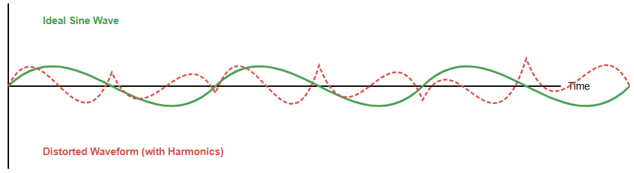
VFIs can cause electricalnoise, called harmonics, which may affect other devices. Filters (passive or active) are often added to solve this problem. Hereunder is the figure that depicts the harmonic distortion.

Installation and Maintenance

Setting up a VFI requires skilled technicians. It has many programmable settings that must be configured properly.

Motor Compatibility

Not all motors are made for VFIs. Older motors may not handle the voltage stress well.
It’s best to use inverter-duty motors for reliable operation.

The Future of VFIs

VFIs are becoming smarter and more efficient. They now connect to the Internet of Things (IoT) for remote monitoring, data analytics, and predictive maintenance. This allows factories to detect issues early and improve uptime.

New materials like Silicon Carbide (SiC) and Gallium Nitride (GaN) make drives faster and more compact. They also waste less heat and improve overall performance. 

In renewable energy, VFIs help control motors in wind turbines and solar systems, balancing power flow to the grid.

Key Takeaways: What is a Variable Frequency Inverter?

This article explained about is what is a VFI, how does it work, the benefit of using it, the common applications and the future of VFI. It also detailed about the future perspective of the VFI.

In short, we learned that a VFI is more than a motor controller. It’s a smart tool that helps save energy, improve performance, and extend equipment life. By converting and adjusting power precisely, it lets motors run exactly as needed.

Although it costs more at first, a VFI quickly pays for itself through efficiency and reliability.

As technology advances, with IoT integration and better semiconductors, VFIs will keep playing a key role in modern industry.

They are essential for creating cleaner, smarter, and more efficient systems around the world.

FAQ: What is a Variable Frequency Inverter?

What is a VFI?

A VFI is a motor controller that varies the frequency and voltage supplied to an AC motor so you can control its speed and torque.

How does a VFI work?

It converts incoming AC power to DC (via a rectifier), smooths the DC (via a DC-bus), then inverts it back to AC with a variable frequency and voltage to control the motor. 

Why use a VFI instead of just running a motor at full speed?

Because you can match the motor speed to what the process really needs. That leads to energy savings, lower mechanical wear, and better process control. 

Where are VFIs commonly used?

They’re used in pumps, fans, compressors, conveyors, HVAC systems, and any rotating equipment where the load varies. 

Can a VFI damage a motor?

If improperly sized, wired, or installed, yes – motors may be subject to higher voltage stress, harmonics, or cooling issues. But when properly used, a VFI actually extends motor life. 

What are the main benefits of using a VFI?

Key benefits: energy savings, speed control, smoother start-stop, less mechanical stress, and process optimization. 

What are some drawbacks or things to watch out for?

Higher initial cost, need for correct installation and settings, potential harmonic distortion in the supply line, motor compatibility issues. 

How do I choose the right VFI for my application?

You’ll look at the motor’s rated power, voltage, phase, speed range, load type (constant vs variable), control features, installation environment, and compatibility. 

How long do VFIs last?

With proper installation, cooling, and maintenance, VFIs often last 10-15 years or more. 

What’s the difference between a VFI, VSD and inverter drive?

These terms are often used interchangeably. A VFD (Variable Frequency Drive) is a type of variable speed drive (VSD). “Inverter drive” is another name focusing on the AC-to-AC conversion aspect.

Predictive maintenance using PLCs

Predictive maintenance is transforming the industrial sector. It uses data to anticipate potential machine failures.

This approach helps companies reduce costs and prevent unplanned stoppages. Predictive maintenance depends on advanced tools. 

Programmable Logic Controllers (PLCs) are a key component. PLCs monitor machine conditions in real time.

They collect data such as temperature and vibration. This information allows maintenance teams to address issues before they become serious. 

Unlike traditional methods, which repair equipment after failure or follow a fixed schedule, predictive maintenance is proactive. It enhances operational efficiency. It keeps factories running smoothly. 

This article surveys the role of PLCs in enabling predictive maintenance. It also explores the benefits, challenges, and future trends of this approach.

Understanding the Basics

Maintenance strategies have evolved over time. Reactive maintenance only addresses problems after a breakdown.

This causes downtime and financial losses. Preventive maintenance follows fixed schedules. 

It replaces components regardless of condition, which can waste resources. Predictive maintenance uses real-time sensor data.

It determines when maintenance is truly needed. Machines provide insight into their own health. 

This enables targeted interventions. This method saves time. It reduces costs and improves overall factory productivity.

The Role of PLCs in Maintenance

PLCs are industrial grade computers that control machinery. They are extremely reliable.

They can operate in harsh environments. Modern PLCs have advanced capabilities. They can collect and process sensor data quickly.

They form the core of predictive maintenance systems. Acting as the central data hub, PLCs connect machines to analytical software. They serve as the operational brain of the system.

Data Acquisition with PLCs

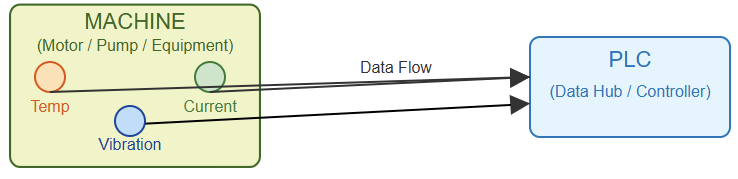
Accurate data is essential for prediction. PLCs collect information from multiple sensors that monitor key machine parameters. Common sensors include vibration detectors. They identify motor or pump wobble. 

Temperature sensors indicate potential overheating. Current sensors monitor power usage.

Fluctuations signal potential issues. PLCs continuously capture this data. They convert physical signals into digital form for analysis.


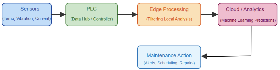
The following figure indicates diagram showing a PLC connected to various sensors on a machine.

Signal Processing and Analysis

Raw sensor readings alone are insufficient. PLCs can perform basic processing locally.

This is known as edge computing. They filter out noise, check for extreme values, and apply logic rules to make initial decisions.

For more advanced analysis, data is sent to centralized systems or the cloud.

There, machine learning algorithms identify patterns indicating imminent failures. By ensuring high quality data, PLCs improve the accuracy of predictive models.

Communication and Connectivity

Fast and reliable data transfer is critical. PLCs use standard industrial protocols like Ethernet/IP, ProfiNet, and Modbus to connect with other systems. They feed data to SCADA systems for human monitoring. 

They also send it to cloud platforms for in-depth analysis. Secure communication is essential. It protects factory networks.

Many modern PLCs include built-in security features. This makes them reliable data gateways.

Machine Learning and Algorithms

Machine learning enables accurate predictions. Algorithms are trained on historical machine data.

They identify normal operating patterns and signs of potential failure. Incoming data is compared against these patterns.

This detects anomalies, estimates time to failure, and recommends maintenance actions.

PLCs provide clean, structured data. This is necessary for algorithms to function effectively.

Common Predictive Maintenance Applications

Many types of machinery benefit from predictive maintenance. Rotating equipment such as motors, pumps, and fans often have predictable wear patterns. Vibration analysis is effective for these machines. 

Monitoring temperature is useful for bearing wear. PLCs also optimize energy usage in HVAC systems.

They monitor entire production lines. This provides a comprehensive view of plant health.

Implementation Challenges

Implementing predictive maintenance systems can be complex. Expertise is required to select appropriate sensors.

Integrating older machinery is also challenging. Data management is difficult. 

Storing and processing large volumes of information can be costly. Cybersecurity is critical.

Staff need training to use new systems effectively. Overcoming these obstacles demands careful planning and proper resources.

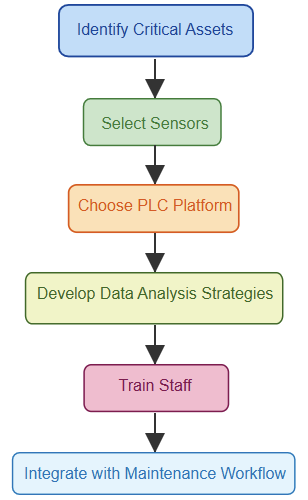
The figure above illustrates a flowchart of a typical predictive maintenance implementation process.

Benefits and ROI

Predictive maintenance delivers substantial returns. It reduces unexpected breakdowns.

It minimizes downtime and lowers maintenance costs. Work is performed only when necessary. This extends equipment life and improves safety. 

By predicting failures, dangerous situations are avoided. Overall Equipment Effectiveness (OEE) increases. This enhances competitiveness and operational performance.

Future Trends and Innovations

The future of maintenance is highly connected and intelligent. Edge computing will become more prevalent.

This allows PLCs to handle complex analysis locally. The Industrial Internet of Things (IIoT) will expand device interconnectivity.

High-speed 5G networks will support faster, more reliable data transmission. Artificial Intelligence (AI) will provide more accurate predictions.

Digital twins virtual models of machines will simulate real world behavior using live PLC data.

Predictive maintenance will continue to evolve toward smarter, fully connected systems.

Case Study: A Manufacturing Plant

A large food processing plant faced frequent pump failures. These failures halted production.

By implementing a predictive maintenance system, PLCs monitored vibration and temperature. Data was analyzed in the cloud. 

This predicted a bearing failure a week in advance. Maintenance was scheduled during a planned downtime.

This avoided an emergency shutdown and saved thousands of dollars. This example highlights the real world effectiveness of predictive maintenance.

Implementation Guide

Launching a predictive maintenance program requires structured steps. First, identify critical assets where failures cause major downtime. Next, select suitable sensors and high quality hardware. 

Choose a PLC platform that supports required communication protocols. Develop data analysis strategies.

Decide on software tools. Finally, train staff and manage change effectively. This ensures adoption.

The upcoming figure stipulates a diagram showing different components of a predictive maintenance architecture)

Key Takeaways: Predictive maintenance using PLCs

This article reviewed the significance of predictive maintenance and the pivotal role of PLCs in enabling proactive industrial operations.

Predictive maintenance is a powerful industrial strategy. PLCs are central to its success. 

They collect vital machine data and enable intelligent decisions. This approach saves time and money. It improves efficiency and enhances workplace safety. Companies can avoid unexpected breakdowns and costly emergency repairs. 

Predictive maintenance also extends the life of machinery and optimizes overall equipment performance.

As factories become increasingly automated, the ability to monitor machine health in real time is essential.

Industries that adopt these technologies gain a competitive advantage. Those that lag behind may face higher costs and increased operational risks.

Looking ahead, AI, IIoT, and digital twins will make predictive maintenance even more precise.

Investing in these systems is more than an operational decision. It is a strategic step toward creating smarter, more resilient, and fully connected factories.

FAQ: Predictive maintenance using PLCs

What is predictive maintenance?

It monitors machine conditions to fix problems before they occur.

How is it different from preventive maintenance?

Preventive follows a fixed schedule; predictive uses real-time data.

What role do PLCs play?

PLCs collect sensor data and send it for analysis.

What data do PLCs monitor?

Temperature, vibration, and current are commonly tracked.

Can PLCs run machine learning?

They do basic processing; advanced analytics run on servers or cloud.

Which communication protocols are used?

Ethernet/IP, ProfiNet, and Modbus.

What are the benefits?

Less downtime, lower costs, longer machine life, better efficiency.

What challenges exist?

Sensor selection, data management, legacy PLC integration, and cybersecurity.

Should old PLCs be upgraded?

Yes. Modern PLCs support better connectivity and analytics.

What’s the future of predictive maintenance?

More AI, edge computing, IIoT, and digital twins.

PLC Loses Program – Reasons and Fixes

Losing a stored program, configuration, or operational state is a serious concern in electronics and automation.

This issue can affect microcontrollers (MCUs), Programmable Logic Controllers (PLCs), and general software systems. 

It often leads to downtime or data loss. The reasons vary widely, from unstable power and hardware damage to software malfunctions and corrupted memory. Understanding these causes is essential for proper troubleshooting. 

PLC Loses Program – Reasons and Fixes

This article surveys the main reasons why programs fail to retain their data. It also provides practical methods to resolve them.

The aim is to help users and engineers maintain dependable and long-lasting systems.

Power Supply Issues

Power instability is one of the most frequent causes of program loss. This is especially true in industrial and embedded systems. Voltage dips (brownouts) and power surges can interrupt normal device operations.

These fluctuations can corrupt the memory that stores the program or its current state.

A sudden power cut during a data write process can prevent proper saving. This leaves the program incomplete or unreadable. 

The program may appear lost when, in fact, the flash memory was never fully updated.

To prevent this, use a stable power source. Adding a surge suppressor or an Uninterruptible Power Supply (UPS) helps regulate voltage. It also protects memory integrity.

The next figure illustrates a diagram showing a regulated power flow through a UPS connected to a control device

Hardware Faults

Defective hardware components can also cause program loss. A malfunctioning non-volatile memory chip might fail to retain data after power is turned off.

Faults in the reset circuit or a corrupted bootloader can prevent the user program from starting.

The code might still be in memory, but it cannot execute. Likewise, damaged printed circuit boards (PCBs) caused by poor soldering or mechanical stress may lead to intermittent faults.

Testing by replacing suspicious parts is a good first step. For MCU-related problems, re-flashing the correct bootloader via an In-System Programmer (ISP) can restore normal function.

Software Bugs and Errors

Programming errors can sometimes imitate program loss. For instance, a software loop or crash may freeze the system and erase its current RAM state. The stored program remains intact, but the device stops operating as intended.

Corruption of configuration files can make the system boot with default settings.

This gives the impression of data loss. Adding robust error handling, watchdog timers, and diagnostic logging (e.g., on an SD card) can help identify these issues.

Proper programming logic should ensure that data saving occurs safely before the system powers down.

Memory Corruption

Memory corruption is another common problem. Electrical noise, interference, or even cosmic radiation can flip bits in memory.

This alters stored data unexpectedly. As a result, programs may behave erratically or fail entirely.

In some cases, invalid memory addressing causes a program to overwrite its own instructions.

This destabilizes the system. Periodic memory testing and using memory with error-correcting codes (ECC) can reduce these risks.

Implementing checksums or CRC validation routines during startup helps detect and isolate corrupted sections.

Incorrect Configuration

Incorrect configuration parameters often prevent a program from starting properly.

A misconfigured I/O port can stop a PLC cycle. An incorrect boot option can stop a microcontroller from launching user code.

These problems usually arise after updates or manual adjustments. To avoid them, always review configuration settings thoroughly.

Keeping a verified backup of configuration files in a secure location helps ensure easy recovery.

Comparing stored settings with an original version after reboot confirms whether the issue is configuration-related or a true program loss.

Firmware Issues

Outdated or unstable firmware can introduce memory and power handling bugs. Certain firmware builds may fail to properly save or restore data during reboots. This leads to missing or corrupted programs. 

Regularly checking for manufacturer firmware updates is crucial. Installing a tested and stable version can resolve these hidden problems.

For instance, updating the firmware on a Pi Pico running CircuitPython has been known to fix disappearing program issues.

Data Storage Failure

When programs rely on external storage, corruption or wear-out of that storage medium can cause data loss.

SD cards and USB drives may fail over time or during improper shutdowns. This results in missing configuration files or lost historical logs. 

Although the main software might still run, its functionality is reduced without access to stored data.

Performing periodic backups and using high-quality, industrial-grade storage solutions minimize the risk.
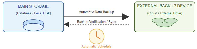
The afore exhibited figure indicates a diagram showing automatic data backup from main storage to an external device.

Environmental Factors

Environmental stress can severely impact electronic devices. Overheating can degrade components.

Humidity can cause short circuits. Constant vibration can loosen connectors or damage PCBs. 

Maintaining the device within its specified environmental limits is vital. Using protective enclosures, stable mounting systems, and controlled ventilation helps preserve long-term reliability, even in harsh conditions.

EMI and RFI

Electromagnetic interference (EMI) and radio frequency interference (RFI) are common in industrial environments that contain a variety of electrical equipment. Anything from handheld radio transmitters used by maintenance staff, to a large motor starting can cause interference.

Companies need to control electrical noise as much as possible, because it can lead to intermittent faults or unusual behavior and even PLC failure.

There are many ways to mitigate the risk of downtime caused by electrical noise through design.

A service engineer can recommend ways to minimize noise by relocating sensitive equipment, segregating systems with high power components and adding barriers, grounding, or shielding cable between sensitive equipment.

Debugging and Troubleshooting

A structured troubleshooting process is essential to identify the real cause of program loss.

Start by verifying if the code remains in memory after a restart. Use a programmer to read and compare memory content with the original file. 

Check all voltage inputs for spikes or drops using a multimeter. Record error logs before shutdown to detect when failures occur.

This methodical approach helps narrow down whether the fault lies in power, hardware, or software. It saves both time and resources.

Managing the Risks

Prevention is more effective than repair. Schedule regular system maintenance and back up all program files frequently.

Document every modification to the hardware or software. Choose components from reputable brands.

Train staff on proper shutdown procedures. These actions increase system stability. They also drastically reduce the chances of losing important programs or configurations.

Key Takeaways: PLC Loses Program – Reasons and Fixes

This article reviewed the most common reasons for program loss and presented practical solutions for each. Losing a stored program is a serious but manageable problem. 

Most causes can be traced to power fluctuations, hardware faults, software errors, or environmental stress. With careful diagnosis and preventive strategies, such incidents can be avoided. 

Stable power delivery, reliable components, updated firmware, and well-written code form the foundation of a resilient system.

A strong troubleshooting process ensures that problems are detected early before they cause major downtime.

Regular maintenance and backups protect vital data from accidental loss. Training personnel on safe shutdown procedures and correct system handling also improves reliability. 

By combining technical precision with preventive care, users can greatly reduce the risk of losing their programs.

Ultimately, maintaining clean power, solid hardware, and disciplined software practices leads to safer, longer-lasting, and more dependable electronic systems.

FAQ: PLC Loses Program – Reasons and Fixes

What is program loss?

It’s when a stored program, configuration, or system state becomes corrupted, erased, or fails to run properly.

What causes program loss?

Power issues, faulty hardware, software bugs, memory corruption, bad configuration, firmware errors, or harsh environments.

How can power problems cause program loss?

Voltage dips, spikes, or sudden outages interrupt memory writes, leading to incomplete or corrupted data.

What hardware faults can lead to program loss?

Defective memory chips, bad bootloaders, damaged PCBs, or unstable reset circuits.

Can software bugs erase programs?

Not always. But logic errors or crashes can corrupt configuration files or stop execution.

What is memory corruption?

It’s when stored data changes unexpectedly due to interference, faulty addresses, or cosmic rays.

How can configuration errors cause problems?

Wrong I/O or boot settings may stop the program from starting, even if it’s still in memory.

Why is firmware important?

Old or buggy firmware can mishandle memory and power cycles, causing data loss.

What about external storage?

Corrupt or worn-out SD cards and drives can erase saved data or configuration files.

Do environmental conditions affect program stability?

Yes. Heat, humidity, or vibration can damage components and lead to failure.

How do I confirm if a program is really lost?

Read the device memory with a programmer and compare it to the original file.

How can program loss be prevented?

Use stable power, quality hardware, backups, good software logic, and routine maintenance.

Is program loss always permanent?

Not necessarily. Sometimes it’s a configuration or startup issue, and the data can be recovered. 

The Ultimate Guide: How to Use a Multimeter for Beginners

If you could only have one tool for electrical work, a multimeter should be it. Think of it as the stethoscope for diagnosing electrical issues.

Whether you’re figuring out why a light switch isn’t working, testing a battery, or building a robot, knowing how to use a multimeter is a fundamental skill.

At its core, a multimeter is a multi-tool that combines several electrical measurement functions into one device. The three most common are:

  • Voltage (V): The electrical potential, like water pressure in a pipe.
  • Current (A): The flow of electricity, like the flow rate of water.
  • Resistance (Ω): How much a material opposes the flow of electricity, like a kink in a hose.

There are two main types: Analog (with a swinging needle) and Digital (with a digital display).

For this guide, we’ll focus on Digital Multimeters (DMMs), as they are the most common, easier to read, and more accurate for most users.

Safety First! Critical Tips Before You Start

Electricity demands respect. Following these safety rules is the most important part of learning how to use a multimeter.

Start with a Known Working Meter

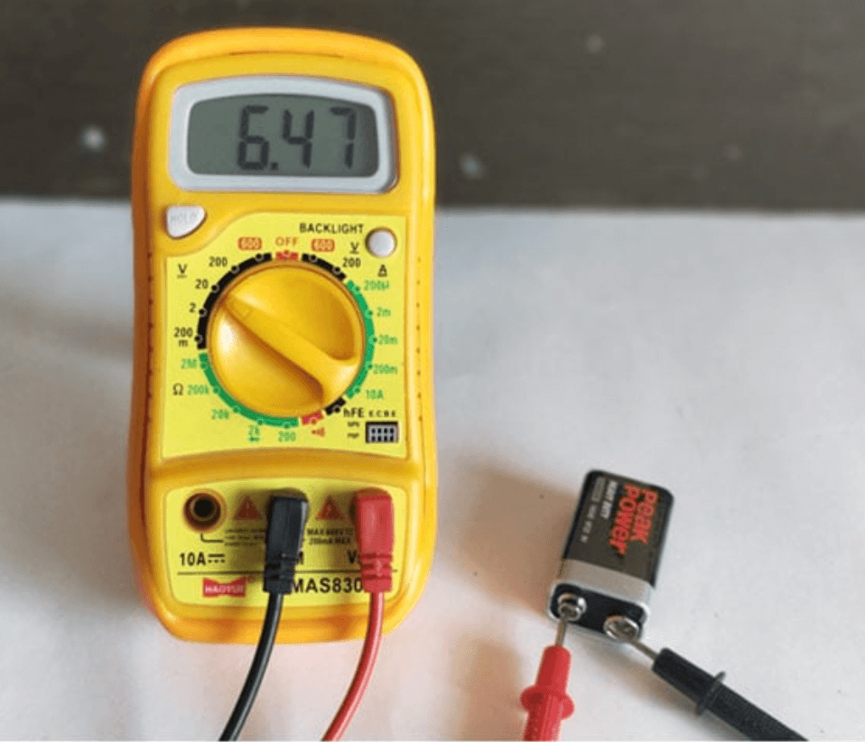
Test your multimeter on a known voltage source, like a new battery, before using it on an unknown circuit.

Check Test Lead Insulation

Never use leads with damaged or cracked insulation.

Never Touch the Metal Tips

Always hold the probes by the insulated, colored handles.

Start with a Higher Range

When measuring an unknown value, start with the highest setting on the dial to avoid damaging the meter.

Be Extra Careful with Mains Voltage

Treat all household AC voltage as dangerous. If you are a beginner, practice on low-voltage DC circuits (like batteries and breadboards) first.

How to Measure Voltage (AC & DC)

Voltage is the most common measurement. It’s measured in parallel with the circuit, meaning you touch the probes to two points in a live circuit.

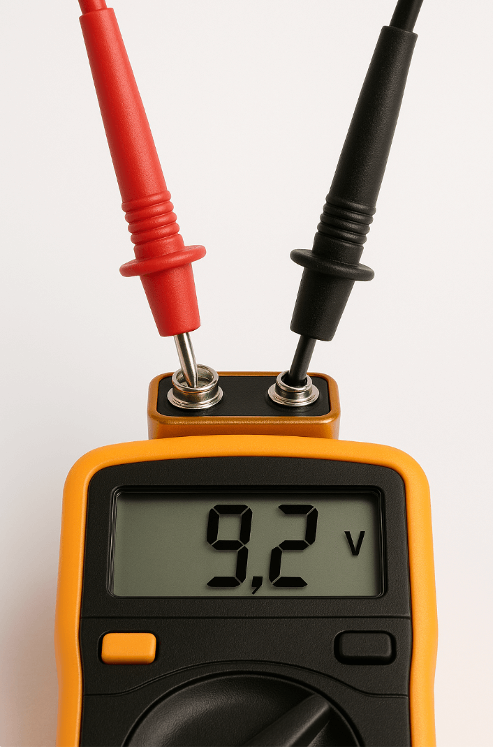
Step-by-Step: Measuring DC Voltage (e.g., a Battery)

  1. Plug in Leads: Black to COM, Red to VΩmA.
  2. Set the Dial: Turn the dial to the “V” with a straight line (⎓) for DC Voltage. If your meter has auto-ranging, you’re set. If it’s manual, choose a range higher than you expect (e.g., 20V for a 9V battery).
  3. Connect the Probes: Touch the black probe to the negative (-) terminal and the red probe to the positive (+) terminal.
  4. Read the Display: The screen will show the voltage. If you get a negative number, you’ve swapped the probes, this is harmless.

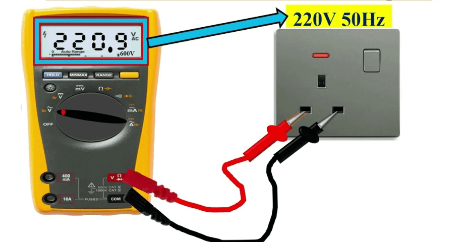
Measuring AC Voltage (e.g., a Wall Outlet) – USE EXTREME CAUTION

  1. Plug in Leads: Black to COM, Red to VΩmA.
  2. Set the Dial: Turn the dial to the “V” with a wavy line (~) for AC Voltage. Choose a range higher than 120V/240V, depending on your region.
  3. Connect the Probes: Carefully insert the probes into the outlet slots. It doesn’t matter which probe goes in which slot for AC.
  4. Read the Display: You should get a reading close to 120V or 240V.

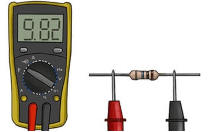
Step-by-Step: Measuring Resistance of a Resistor

  1. Plug in Leads: Black to COM, Red to VΩmA.
  2. Set the Dial: Turn the dial to the Ohm symbol (Ω).
  3. Connect the Probes: Touch the probes to each end of the resistor. The orientation doesn’t matter.
  4. Read the Display: The meter will show the resistance in Ohms (Ω), kilo-ohms (kΩ), or mega-ohms (MΩ). Compare it to the resistor’s color bands.

How to Test for Continuity

This is my favorite function for troubleshooting! Continuity tests if two points are electrically connected.

A good connection (like a closed switch or unbroken wire) will cause the meter to emit a continuous beep.

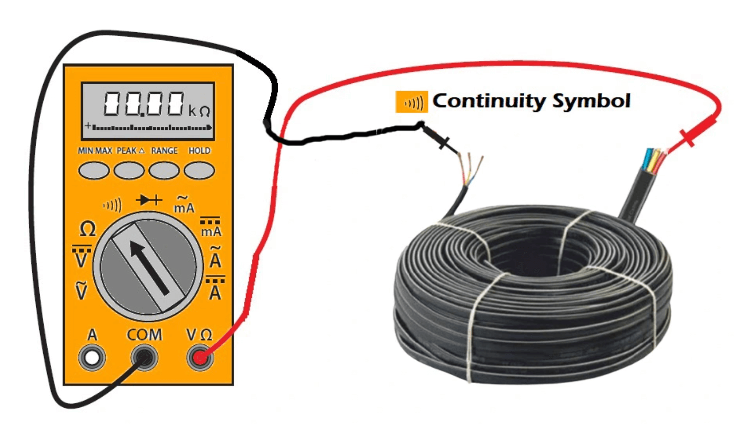
Step-by-Step: Checking a Fuse or Wire

  1. Plug in Leads: Black to COM, Red to VΩmA.
  2. Set the Dial: Turn the dial to the continuity symbol (⋅⋅⋅) or a diode symbol (➲). This is often combined with the resistance setting.
  3. Test the Meter: Touch the two probe tips together. You should hear a clear beep, confirming the function works.
  4. Test the Component: Touch the probes to both ends of a fuse or wire. A beep means the fuse/wire is good (it has continuity). No beep means the path is broken and the component is faulty.

How to Measure Current (AC & DC)

Warning: This is the most dangerous function for your multimeter if done incorrectly. Measuring current requires the meter to be part of the circuit, meaning electricity must flow through it.

Step-by-Step: Measuring Small DC Current

  1. Plug in Leads: Black to COM, Red to VΩmA.
  2. Set the Dial: Turn the dial to the “A” with a straight line (⎓) for DC Current. Start with the highest current range (e.g., 10A).
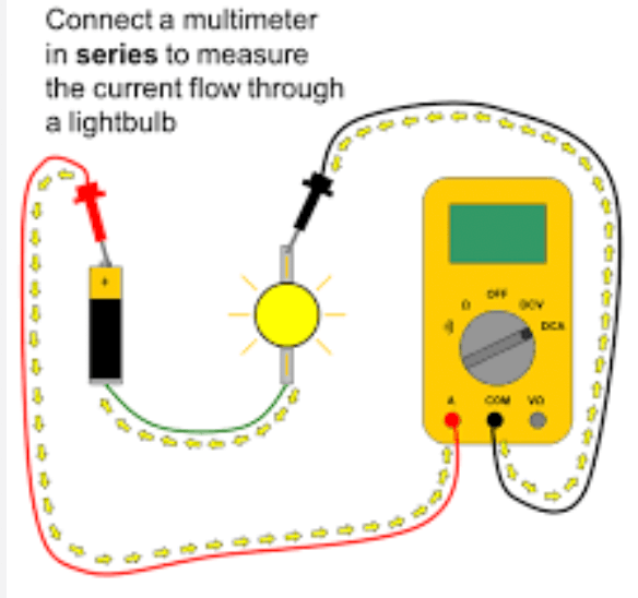
  3. Break the Circuit: You must interrupt the circuit and place the multimeter in series. This means the current flows from the circuit, into the red probe, through the meter, and out the black probe back into the circuit.
  4. Read the Display: The meter will show the current in Amps (A) or milliamps (mA).

Common Multimeter Uses & Troubleshooting Scenarios

Testing a Battery

Use the DC Voltage setting. A 9V battery reading below 8.5V is likely dead.

Checking a Light Switch

Use the Continuity setting. With the power OFF, test across the switch terminals. It should beep when ON and not beep when OFF.

Identifying Wires

Use the Continuity setting. Connect one probe to a known wire end and touch the other to unknown ends until it beeps.

Key Takeaways: How to Use a Multimeter

Learning how to use a multimeter unlocks a world of DIY electrical and electronic projects.

Start with the basics, voltage and continuity, in safe, low-voltage environments. Always prioritize safety, and soon you’ll be diagnosing problems with confidence.

Remember, a multimeter is not just a tool; it’s your window into the invisible world of electricity.

Now, go grab your meter and start testing

FAQ: How to Use a Multimeter

What is the difference between auto-ranging and manual multimeters?

An auto-ranging multimeter automatically selects the correct measurement range for you.

You just set the dial to “V” for voltage, and it figures out if it’s millivolts or hundreds of volts. This is great for beginners.

A manual multimeter requires you to select the approximate range yourself. If you’re measuring a 12V car battery, you’d select the 20V DC range, not the 200mV range. Manual meters are often cheaper but require a bit more knowledge.

Can a multimeter measure AC current?

Yes, most multimeters can measure AC current (using the “A~” setting), but it is less common and can be more dangerous than measuring DC current.

For measuring mains AC current, a much safer and more convenient tool is a clamp meter, which can measure current by clamping around a wire without breaking the circuit.

For most DIYers, measuring AC voltage is sufficient for troubleshooting household issues.

Why does my multimeter show 0L or 1 when I try to measure?

When you see 0L (overload) or 1 on the left side of the display, it means the value you’re trying to measure is outside the selected range. This is very common with manual-ranging meters.

When measuring voltage or current

The value is too high for the selected range. Turn the dial to a higher range (e.g., from 2V to 20V).

When measuring resistance

The value is infinite, meaning there is no electrical path (an open circuit). This is what you’d see when testing a broken wire or a blown fuse.

What does it mean if my resistance reading is 0 ohms?

A reading of 0 ohms (or very close to 0, like 0.4) indicates a short circuit or a perfect conductor.

There is virtually no resistance to the flow of electricity. For example, this is what you’d see if you touched the two probes together or tested a piece of pure, unbroken copper wire.

How do I test if a fuse is blown without power?

Use the Continuity Test function.

  1. Remove the fuse from the circuit.
  2. Set your multimeter to the continuity mode (the sound wave symbol ⋅⋅⋅).
  3. Touch a probe to each metal end cap of the fuse.
  4. If you hear a beep: The fuse is good, and the internal wire is intact.
  5. If there is no beep: The fuse is blown, and the circuit is broken inside.

Can I get shocked using a multimeter?

The risk exists, but you can minimize it by following safety protocols. The danger is highest when measuring household AC voltage. Always:

  • Use leads with proper insulation.
  • Never work on a live circuit with wet hands or in a damp environment.
  • Set the meter to the correct function before connecting the probes.
    For low-voltage DC circuits (batteries, car electronics, Arduino projects), the risk of a dangerous shock is extremely low.

What should I look for when buying my first multimeter?

For a beginner, I recommend a basic digital auto-ranging multimeter. Key features to look for:

  • Auto-ranging (simplifies use)
  • Continuity test with audible beep (invaluable for troubleshooting)
  • Diode test function
  • Overload protection (safety feature)
  • A sturdy build and a clear stand. You don’t need a professional-grade Fluke for home use; brands like AstroAI, Innova, and Klein Tools offer excellent entry-level mod