PLC PID Control Explained Simply

A PID controller is the brain behind many automated processes. It helps a system automatically maintain a specific target, or “setpoint,” with great accuracy.

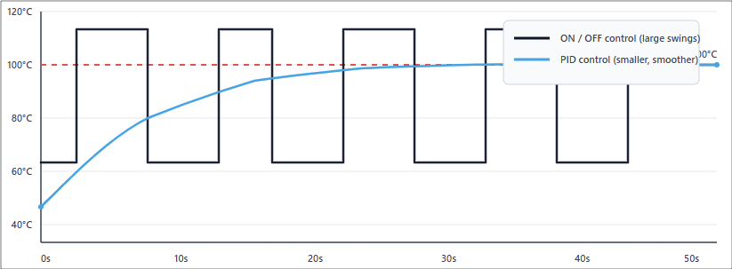
Unlike a simple ON/OFF switch, which can cause large swings, a PID uses a clever formula to make smooth, precise adjustments.

 In industrial settings, PID control is often run by a Programmable Logic Controller (PLC).

The PLC executes the PID algorithm and translates its calculations into commands that control machinery. 

This article will explain the core concepts of PLC PID control. It will break down how the “Proportional,” “Integral,” and “Derivative” terms work together to create a feedback loop that achieves and maintains a setpoint. 

We will explore the common challenge of “tuning” and provide practical examples of how PLC PID control is used in the real world. 

PLC PID Control Explained Simply

The Problem with Simple Control

Let’s begin with a relatable example: controlling the temperature in an oven. In the simplest system, this works like a light switch:

  • The oven’s setpoint is the desired temperature.
  • A sensor measures the current, actual temperature.
  • If the temperature is too low, the controller turns the heater ON.
  • If the temperature is too high, the controller turns the heater OFF.

This strategy is known as ON/OFF control. It is simple, but it has a big problem. It causes constant swings above and below the setpoint. The heater overshoots, then shuts off, then undershoots, and the cycle repeats.

This leads to inefficiency. The equipment experiences more stress and wears out faster.

For processes where high precision matters, like chemical reactions or semiconductor manufacturing, this is unacceptable.

That is why industries use PID control. It takes a smarter approach, one that reduces oscillations and provides smoother, more accurate control.

The Foundation: The Feedback Loop

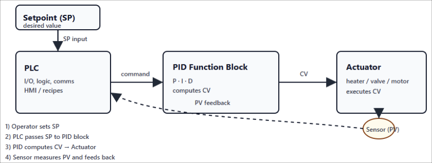
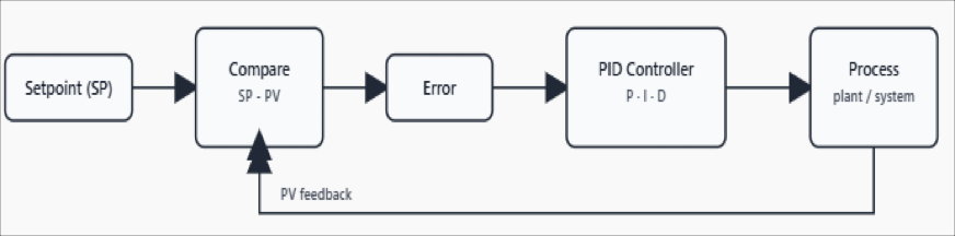
At the heart of PID control lies a feedback loop. This is the continuous cycle where the system checks itself, compares values, and makes corrections.

There are four key parts to understand:

Setpoint (SP)

The target value. For example, keeping an oven at exactly 100 °C.

Process Variable (PV)

The actual measured value. This comes from a sensor, like a thermometer.

Error (E)

The difference between the setpoint and the process variable. Formula: E = SP – PV.

Control Variable (CV)

The output signal calculated by the PID algorithm and sent by the PLC to the equipment. For an oven, this could be the amount of power delivered to the heater.

The goal of the PID controller is simple in theory: make the error as close to zero as possible.

But in practice, achieving that balance requires the three components: P, I, and D — to work together. Each has a unique role in shaping how the system reacts.

The P, I, and D Explained

Proportional Term (P) – Reacting to the Present

The Proportional term is the most direct part of the equation. It creates a correction that is proportional to the size of the error.

  • If the error is big, the correction is big.
  • If the error is small, the correction is small.
  • As you approach the setpoint, the adjustment becomes gentler.

You can compare it to pressing the gas pedal in a car. If you are far from your target speed, you press harder. As you get close, you ease off.

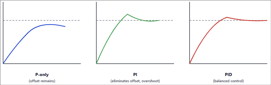
But proportional control has a weakness. It often leaves a small, constant error known as offset.

This happens because the controller always needs some error to generate an output. The system gets close to the setpoint, but not exactly there.

Integral Term (I) – Learning from the Past

The Integral term solves the offset problem. It looks at the error not just in the present, but over time.

  • It adds up the error history, essentially remembering how long and how large the error has been.
  • If a small error keeps occurring, the integral term grows until it pushes the system to eliminate it completely.
  • Over time, this ensures the process reaches the exact setpoint.

But there is a catch. If the integral is set too strong, the system can overshoot. This means it goes past the setpoint and swings back, sometimes several times.

A related issue is integral windup, where the integral keeps building even when the actuator is already at maximum output.

Derivative Term (D) – Predicting the Future

The Derivative term acts like a predictor. It looks at how quickly the error is changing and estimates where it is headed.

  • If the error is rising fast, the derivative provides a damping force to slow it down.
  • This prevents overshoot and improves stability.
  • It is especially useful in fast-moving processes, like speed control in motors.

However, derivative control is sensitive to noise. If the sensor signal is noisy, the derivative will amplify it, causing jerky outputs. For this reason, many industries use just PI control instead of full PID.

The Role of the PLC

In the past, engineers had to build dedicated hardware for PID control. Today, modern PLCs make it much easier. They come with built-in PID function blocks.

Integration

A PLC connects the sensor inputs (PV) and the actuators that carry out the control variable (CV).

Programming

In the PLC software, you simply insert a PID block, connect the PV and SP signals, and link the output to the device.

Tuning

The PLC stores the gain values for P, I, and D. You can adjust them directly through the interface.

This makes PID implementation more accessible. Even technicians who are not control theory experts can use PLC software to set up and tune loops.

Tuning Your PID Loop

Tuning is the art of adjusting the P, I, and D parameters until the system behaves well. The perfect settings depend on the process.

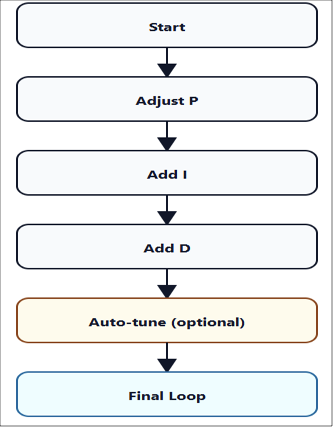
Start with P

Begin with only proportional control. Increase the gain until the system starts to oscillate, then reduce it to about half.

Add I

Introduce a small integral value. This removes steady-state error. Increase it slowly until the error disappears without causing big swings.

Add D (if necessary)

If your process reacts quickly or tends to overshoot, add a little derivative action for damping.

Auto-tune

Many modern PLCs have an auto-tune feature. The system runs a test, observes behavior, and automatically suggests PID values.

Good tuning balances speed, accuracy, and stability. Poor tuning causes overshoot, oscillations, or sluggish response.

Real-World Examples

Let’s look at where PID control in PLCs is actually used:

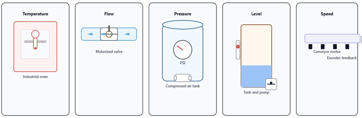
Temperature Control

In an industrial oven, the PLC reads temperature from a thermocouple (PV). It compares it to the setpoint (SP). The PID output adjusts gas or electric heaters. The result is precise, stable heating.

Flow Control

In pipelines, a PLC measures flow rate with a flow meter. The PID loop adjusts a motorized valve. This keeps the liquid flowing at the correct rate.

Pressure Control

In compressed air systems, a PID loop keeps tank pressure constant. It does this by controlling a compressor or a pressure valve.

Level Control

In tanks, the PLC monitors liquid level with a sensor. The PID loop controls pumps or valves to maintain the level.

Speed Control

Conveyor belts often require consistent speeds. A PID loop uses feedback from an encoder and adjusts the motor drive to hold steady speed.

Key Takeaways: PLC PID Control Explained Simply

PLC PID control is one of the most important tools in industrial automation. It is flexible, powerful, and surprisingly simple once you understand the basics.

Instead of crude ON/OFF control, a PID controller gives you three smart strategies — Proportional, Integral, and Derivative.

Together, they make the system respond not only to the present error, but also to past trends and future predictions.

A well-tuned PID loop can handle small drifts, sudden disturbances, and long-term stability.

Thanks to modern PLCs, implementing PID is easier than ever. Built-in blocks and auto-tuning make advanced control accessible even for non-specialists.

The payoff is huge: stable processes, better quality products, reduced wear on equipment, and more efficient energy use.

With a strong grasp of PID basics, you can start unlocking the full power of your automated systems.

FAQ: PLC PID Control Explained Simply

What does “PID” stand for in a PID controller?

PID stands for Proportional, Integral, and Derivative. These are the three control actions or terms that combine to determine the controller’s output based on how far, how long, and how fast the system error is changing.

What is a PID controller’s basic purpose?

A PID controller continuously compares a process variable (PV) with a desired setpoint (SP).

It then calculates an error (SP − PV), and uses the P, I, and D terms to adjust the output in order to reduce that error. The goal is to bring the process variable to the setpoint and keep it stable.

What does each term (P, I, D) do?

Proportional (P): Reacts to the current error. Larger error → larger correction. Helps reduce rise time but can leave a steady-state error.

Integral (I): Accumulates error over time. It addresses steady error or offset that P alone cannot eliminate.

Derivative (D): Looks at the rate at which error is changing. It acts to dampen or slow the controller’s response to prevent overshoot or oscillations. It’s like anticipating what might happen next.

Why is PID tuning important, and what are some common tuning methods?

Tuning means selecting or adjusting the gains (or time constants) of P, I, and D so the controlled process responds nicely (fast, stable, minimal overshoot, minimal steady error).

Without good tuning, the system might oscillate, respond too slowly, or constantly overshoot. 

Common tuning methods include: Manual tuning, by observing system behavior (e.g. increase P until borderline oscillation, then adjust I and D).

Auto-tuning, where the controller itself runs experiments to estimate good gains; Empirical rules like Ziegler-Nichols method.

What is “integral windup”, and how can it be prevented?

Integral windup occurs when the integral term builds up too much error — for example while the output is saturated (at its maximum or minimum limit) and cannot respond further.

When the constraint is removed, this “built up” integral can lead to overshoot or long settling times.

Prevention strategies include: Limiting or bounding the integral term; Using anti-windup logic (e.g. disabling integration when output is saturated or using back-calculation).

Can a PID controller have a simple ON/OFF output?

Yes, though that depends on application. The core PID algorithm usually produces an analog or continuously varying output.

But in some systems, that analog output is converted (via things like PWM or duty cycling) into ON/OFF switching to control physical devices (like heaters) that can’t respond continuously. 

What are the limitations of PID control?

Some limitations include: Sensitivity to noise, especially in the derivative term. Difficulties with non-linear systems or processes whose behavior changes with operating conditions.

Challenges in responding to large or sudden disturbances or changes in setpoint. If the system has long delays (dead time), PID can struggle; Potential overshoot or oscillations if tuning is not done properly. 

What is a “control loop” and what types are there?

A control loop refers to the cycle where the system measures a variable (PV), compares it with the desired value (SP), computes the error, uses a controller to adjust an actuator (CV), and affects the process, which feeds back into PV. This happens continuously.

Types include: Open loop, where no feedback is used — the controller doesn’t see the output; Closed loop, which is what PID control is — feedback is used to adjust continuously. 

How does the derivative term affect stability?

The derivative term adds damping. It helps reduce overshoot and smooth out fast changes.

That improves stability when things are changing rapidly. However, if derivative gain is too large, or if the sensor signal is noisy, it can cause erratic controller output or instability. 

What is “dead time” and how does it impact PID control?

Dead time (or delay) is the time lag between when the controller output changes and when its effect is first observed in the process variable. Long dead times make control harder because the system reacts slowly.

They can degrade performance, cause overshoot or oscillation, or make tuning more difficult. 

When might you use PI control instead of full PID?

PI (Proportional + Integral) control is often enough when the process is slower, or derivative action is not helpful (for example because of sensor noise, or small benefit versus complexity).

Many industrial applications omit the derivative term to simplify control and avoid amplifying noise. 

Dedicated PID devices vs. using a PLC for PID loops — which is better?

It depends on scale and complexity: Dedicated devices (stand-alone PID controllers) are good for simple, localized control (one loop, local HMI), fast deployment, less programming overhead.

PLCs are better when you need multiple loops, integration with other automation logic, data logging, supervising, HMI, alarms, etc.

They offer flexibility, communication, easier maintenance when multiple loops or complexity are involved.

What is a PLC Input Module?

Programmable Logic Controllers (PLCs), are the heart of modern automation. They control machines, manage processes, and keep factories running smoothly. One of the most important parts of a PLC system is the input module. 

Without inputs, the PLC would not know what is happening in the real world. Inputs are the “eyes and ears” of the controller.

They bring signals from sensors, switches, and other devices into the PLC so it can act.

This article explains what a PLC input module is, how it works, why it matters, and where it is used.

It also covers different types, wiring considerations, and practical examples. By the end, you will understand the vital role of PLC input modules in automation.

The Role of a PLC in Automation

A PLC is a special industrial computer. It is built to survive harsh environments, like hot factory floors or dusty production lines.

Its main job is to take in information, make decisions based on programmed logic, and send out commands.

The cycle is:

  • Inputs come in from the field.
  • The PLC processes those signals.
  • Outputs are activated to control machines.

Inputs tell the PLC what conditions exist. Outputs allow the PLC to change things. If the input side fails, the whole system fails. That is why the input module is so critical.

What is a PLC Input Module?

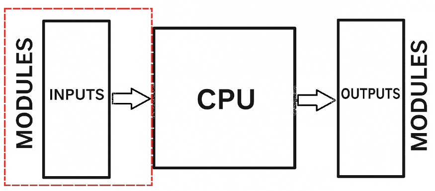
An input module is a hardware component of the PLC. It is designed to receive electrical signals from external devices.

These signals can be digital (ON/OFF) or analog (variable values). The module translates the external signals into a format the PLC’s CPU can understand.

Think of it as a translator. Machines and sensors speak the language of voltage and current.

The PLC CPU speaks binary data. The input module sits in the middle and makes communication possible.

Types of Input Signals

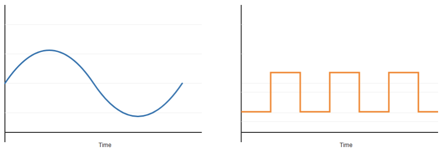
Based on time and magnitude, inputs can be divided into two broad categories.

Digital Inputs

Digital inputs are simple. They can only be ON or OFF. A push button is pressed or released.

A limit switch is open or closed. A sensor detects an object or not. The input module reads these states and passes them to the PLC CPU as 1 or 0.

For example:

  • A float switch shows if a tank is full.
  • A proximity sensor detects a metal part.
  • A start button sends a signal when pressed.

Digital inputs are the most common in automation.

Analog Inputs

Analog inputs handle values which are continue in time and continue in magnitude.

Instead of just ON or OFF, they measure a range. They can read temperature, pressure, speed, or level. These values are usually represented as a voltage (0–10 V) or current (4–20 mA).

For example:

  • A flow meter outputs a current based on flow rate.
  • A pressure transducer shows how much pressure is in a pipe.
  • A temperature sensor sends a varying signal.

Analog input modules must convert these signals into numbers the CPU can process. This is done through an Analog-to-Digital Converter (ADC).

How Input Modules Work

The operation of an input module may seem simple, but it involves several steps.

Signal Detection

The module receives a signal from the field device. This could be voltage from a switch or current from a sensor.

Conditioning

The signal is adjusted. For digital inputs, noise may be filtered out. For analog inputs, scaling and isolation are applied.

Conversion

In the case of analog inputs, the signal is converted from analog to digital.

Communication

The processed signal is sent to the CPU. The CPU then updates its memory with the input state or value.

The entire process happens quickly. PLCs scan inputs, process logic, and update outputs many times per second. This ensures real-time control of machines.

Importance of Input Modules

The input module is the only way the PLC knows what is happening in the system. Without accurate inputs, the controller is blind. Imagine driving a car with no dashboard, no speedometer, and no fuel gauge. 

You would not know when to accelerate or stop. That is how a PLC feels without inputs.

Reliable inputs ensure safe and efficient operation. They prevent accidents, reduce downtime, and improve productivity.

If an input fails, machines may run out of sequence or cause damage. That is why input modules are built with high reliability.

Types of Input Modules

There are many types of input modules. The type depends on the signals they handle.

Analog Input Modules

Handle continuous signals like 0–10 V or 4–20 mA.

Digital Input Modules

Handle binary signals like 24 V DC or 120 V AC.

High-Speed Input Modules

Handle fast signals, such as from encoders.

Specialty Modules

Designed for specific sensors, like thermocouples or RTDs.

Each type is chosen based on the application. For example, a packaging line may use mostly digital inputs, while a chemical process may use many analog inputs.

Input Voltage Levels

Different industries use different voltage standards. Common levels for digital inputs include:

  • 48 V DC or 230 V AC: less common but used in some cases.
  • 120 V AC: common in older systems.
  • 24 V DC: most common in industry.

The input module must match the field voltage. Connecting the wrong voltage can damage the module.

For analog inputs, the standard signals are:

  • 0–10 V
  • ±10 V
  • 4–20 mA

The 4–20 mA current loop is very popular because it resists noise and allows long cable runs.

Security in Input Modules

Input modules often include electrical isolation. This is usually done with optocouplers or transformers.

Isolation protects the CPU from voltage spikes and noise. It also prevents ground loops.

Without isolation, a fault in a sensor could damage the entire PLC. With isolation, the fault is contained. This makes systems safer and more reliable.

Wiring Considerations

Correct wiring is essential for input modules. For digital inputs, each sensor or switch must be wired to the correct terminal.

Polarity must be respected for DC signals. For AC signals, the line and neutral must be connected properly.

For analog inputs, shielding is often used. Shielded cables reduce electrical noise. Grounding must be done correctly to avoid interference. In current loops, the loop must be complete for the signal to be read.

Poor wiring can cause false signals, noise, or even damage. Careful installation prevents these issues.

Diagnostics and Indicators

Modern input modules include diagnostic features. Each input channel often has an LED indicator. This shows if the input is active. This helps technicians during troubleshooting.

Some advanced modules can detect wiring errors, short circuits, or broken sensors.

They send diagnostic data to the CPU. This reduces downtime and improves maintenance.

Input Modules in Redundant Systems

In critical industries, redundancy is used. This means having two input modules for the same signals.

If one fails, the other continues working. Redundancy is common in power plants, oil and gas, or aerospace systems.

Evolution of Input Modules

Input modules have evolved with technology. Early PLCs had simple digital input cards.

Today, modules are smarter. They can filter noise, scale analog values, and provide diagnostics.

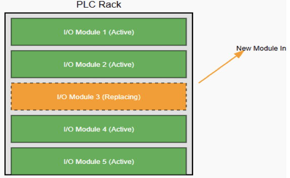
Some even support hot swapping, meaning they can be replaced while the PLC is running.

With Industry 4.0, input modules are also becoming networked. They can communicate over Ethernet and send data directly to higher-level systems.

Safety Input Modules

Safety is critical in automation. Special safety input modules are used for emergency stop buttons, light curtains, and safety mats.

These modules are designed to meet strict safety standards. They often use redundancy and self-checking. This ensures that faults are detected quickly.

Cost and Selection

The cost of input modules depends on type and features. Digital input modules are cheaper than analog ones.

High-speed or safety modules cost more. When selecting, engineers must balance cost with reliability and function.

Key factors include:

  • Number of inputs required.
  • Voltage levels.
  • Need for analog or digital.
  • Diagnostic features.
  • Safety requirements.

Maintenance and Troubleshooting

Maintaining input modules involves regular checks. Technicians should verify LED indicators, measure voltages, and check wiring.

Faulty sensors or loose connections are common issues. Modern PLC software also helps. It shows live input status on the screen, making troubleshooting easier.

Key Takeaways: What is a PLC Input Module?

This article explained what a PLC input module is, how it works, why it matters, and where it is used.

It also detailed different types, wiring considerations, and practical examples. 

From the discussion, we are able to say that the PLC input module may look simple, but it is the foundation of automation.

It connects the real world to the digital brain of the PLC. Without it, machines cannot be controlled, and processes cannot be automated.

Digital inputs bring simple signals like ON or OFF. Analog inputs bring continuous measurements like temperature or pressure.

Together, they give the PLC the information it needs. Input modules protect, condition, and translate these signals reliably.

From conveyor belts to water plants, input modules are everywhere. They make automation safe, efficient, and productive.

As technology evolves, input modules will only become smarter and more connected. But their basic role will remain the same: to be the eyes and ears of the PLC.

FAQ: What is a PLC Input Module?

What is a PLC Input Module?

Hardware component within a PLC that receives signals—digital or analog—from field devices like switches and sensors, and converts them into a format the PLC’s CPU can process.

Why is it important?

It acts as the PLC’s “eyes and ears.” Without it, the PLC cannot detect changes in its environment, making accurate control of machines or processes impossible.

What types of input modules are there?

There are three primary types: Digital (Discrete) Modules – Handle ON/OFF signals like buttons or limit switches.; Analog Modules – Handle continuous signals such as temperature, pressure, or flow, converting them via built-in ADCs.; Network I/O Modules – Handle I/O communication over industrial networks like Ethernet or Profibus. 

How does an input module function?

For digital inputs, it detects ON/OFF states and sends binary signals to the CPU. For analog inputs, it receives continuous voltage or current and converts it into digital form for CPU interpretation.

Many modules also include LED indicators and built-in diagnostics to aid troubleshooting.

What voltage levels do input modules support?

  • Digital input modules typically support ranges such as 12–24 V DC or 120 V AC. 
  • Analog modules usually support ranges like 0–10 V or 4–20 mA

Why is electrical isolation important in input modules?

Isolation (e.g., using optocouplers) protects the PLC CPU from voltage spikes, reduces noise, and prevents grounding issues.

In systems with multiple power sources, isolated modules help avoid ground loops and interference.

What are high-density and high-speed modules?

High-density modules pack many channels (e.g., up to 32) into one module—ideal for compact installations.

High-speed modules are designed for fast-changing inputs, such as encoder pulses or rapid sensor signals. 

Can I/O modules be specialized?

Yes. Beyond standard digital and analog, there are modules designed for applications such as:

  • High-speed counting
  • Temperature measurement (e.g., RTDs, thermocouples)
  • Position control or other specialized sensor interfaces

How do you choose the right input module?

Consider: Type of signal (digital vs. analog); Voltage/current range; Channel count; Speed of signal changes; Diagnostic and isolation needs; Compatibility with the PLC system

Can input modules handle multiple power sources?

Yes, isolated modules provide separate commons for each channel or group, allowing safe connection to external power supplies without interference or ground loops.

Are there diagnostic features built into modules?

Many modern modules include LEDs for channel status and diagnostics to detect wiring faults, short circuits, or device failures—greatly simplifying troubleshooting.

How do input modules fit into a PLC system?

Modules are typically placed in a modular rack or chassis, interfacing via the backplane. The CPU reads input states during each scan cycle.

What is Hot-Swapping in PLCs?

Hot-swapping is the ability to replace or insert components in a system while it is still running and powered. This means there is no need to turn OFF the system or interrupt the process.

In the world of Programmable Logic Controllers (PLCs), this function is mostly applied to Input/Output (I/O) modules.

These are the modules that connect the PLC to sensors, actuators, and field devices.

Normally, when a module becomes faulty, the system would need to be stopped, and the power disconnected before replacing the damaged unit. This can cause downtime, lost production, and high costs.

With hot-swapping, however, a technician can pull out the faulty module and slide in a new one while the PLC continues to operate as usual.

This article explains the concept of hot-swapping. It shows its procedures, applications, risks, and finally its advantages and disadvantages.

The Concept of Hot-Swapping

Hot-swapping refers to changing parts of a system while it is still powered on and functioning.

It allows modules to be removed or added without switching off the entire unit. This is very different from cold-swapping.

Cold-swapping requires that the system be completely powered down before any changes are made.

The idea of hot-swapping is not limited to PLCs. It is actually a widely used concept in modern technology. 

For example, every time you plug a USB device into your computer while it is running, you are doing a hot-swap. The computer instantly detects the device and makes it available. 

Servers and data centers also rely heavily on this feature. They use hot-swappable hard drives, power supplies, and network cards to maintain continuous operation. In PLCs, the function is built into the chassis and the modules. 

The modules and their connectors are designed to safely handle insertion and removal while powered. This ensures that the system remains stable and does not crash during the process.

How Hot-Swapping Works in a PLC

For a PLC to allow hot-swapping, both its hardware and software must be specially designed.

It is not something that can be done on just any PLC system. There are several key features that make this possible.

Staggered Pins

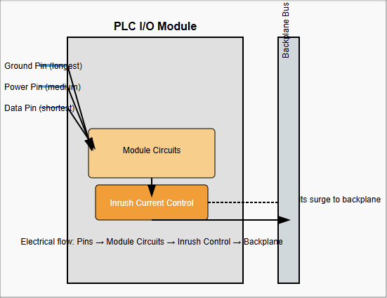
Connectors in hot-swappable modules are not uniform. They have pins of different lengths. The ground and power pins are slightly longer.

This ensures they make contact before any data pins do. When inserting a module, the system first gets a stable ground and power connection.

Only then are the data and communication lines connected. Similarly, when removing a module, the data pins disconnect first, preventing corrupted signals or unexpected shutdowns.

Backplane Design

The modules are connected to the CPU through a backplane or communication bus.

In hot-swappable PLCs, this backplane is carefully engineered to withstand the electrical disturbances that happen when a module is inserted or removed.

It includes circuits and controllers that regulate the process. Each module may also contain its own hot-swap controller.

This manages the way the module powers up and synchronizes with the rest of the system.

Inrush Current Control

When a new module is plugged in, it contains capacitors that are empty. The moment power reaches them, they try to charge instantly, causing a sudden surge of current called inrush current.

If not controlled, this surge could disturb or reset other modules on the backplane. A hot-swap controller inside the module limits this inrush. It ensures the current flows gradually and safely.

Software Management

Hardware alone is not enough. The PLC’s operating system and firmware must also recognize when modules are added or removed.

Some PLCs continue to run even if a module is missing. They may show a fault code but keep the program running.

This prevents the whole process from shutting down. Once a new module is inserted, the system automatically detects it, configures it, and re-establishes communication. The program then returns to normal operation without stopping.

    The Hot-Swapping Procedure

    Performing hot-swapping must always follow a clear procedure. Doing it incorrectly can lead to damage or safety hazards.

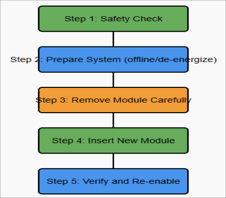
    Safety Check

    Make sure the module is actually designed for hot-swapping. Not all modules allow this.

    Use your hands only. Do not use screwdrivers or metal tools, as they may cause short circuits.

    Prepare the System

    If possible, use the PLC software to place the module in an “offline” state. For I/O modules, disconnect or de-energize the field devices connected to them. This reduces risk during the swap.

    Remove the Module

    Unlock the retaining clips or screws. Disconnect the terminal block. Gently slide the module out in a straight motion. Avoid shaking or twisting.

    Insert the New Module

    Verify that the replacement module is the same type as the original. Align it correctly with the chassis. Push it in firmly until it locks in place.

    Verify and Re-enable

    Once inserted, the PLC detects the new module. Use the software to confirm communication and function. If you disabled the I/O earlier, re-enable it now. Test to make sure it is working correctly.

      Applications of Hot-Swapping

      Hot-swapping is most common in advanced PLC systems, particularly those that are modular or rack-based. It is widely used in:

      Redundant Systems

      In critical plants, two PLCs often run together. One is active, and the other is on standby.

      If a module fails, it can be replaced while the standby system keeps things running. This avoids any interruption.

      Remote I/O

      Many plants use distributed PLC systems with remote I/O racks in different locations.

      Hot-swapping makes it possible to change a remote module without affecting the main PLC. The rest of the plant continues running normally.

      System Upgrades

      Industries often upgrade their equipment step by step. Hot-swapping allows a technician to replace old modules with newer ones while the process continues. This reduces downtime during modernization.

      Risks of Hot-Swapping

      Although the feature is very useful, it also comes with risks. These include:

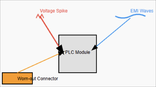
      Voltage Surges

      If a module is faulty or not designed well, inserting or removing it can create spikes in voltage. These spikes may damage the module or even the backplane.

      Electromagnetic Interference (EMI)

      The process of swapping can generate electrical noise. This noise may interfere with data communication inside the PLC. It can cause temporary data loss.

      Connector Wear

      Modules that are swapped too often can wear out their connectors. The metal surfaces can corrode or oxidize over time, leading to poor connections.

      Data Integrity

      If a module is removed while it is actively transmitting data, that data may be lost or corrupted. PLC firmware must be designed to handle this situation gracefully.

      Advantages and Disadvantages of Hot-Swapping in PLCs

      This subsection gives a brief explanation of pros and cons of the hot-swapping in PLCs.

      Advantages

      Reduced Downtime

      Processes keep running with minimal interruption. This is crucial for industries that operate nonstop, such as 24/7 production lines.

      Improved Reliability

      In redundant systems, hot-swapping adds another layer of fault tolerance.

      Simplified Maintenance

      Technicians can replace or upgrade hardware without shutting down the whole system.

      Safer Work

      Technicians may not need to completely power down the PLC cabinet, which reduces time spent working in de-energized conditions. However, standard electrical hazards remain.

      Disadvantages

      Higher Cost

      Hot-swappable PLCs are more expensive. Their backplanes and modules require advanced designs.

      Complexity

      These systems are technically more complex, requiring careful engineering and support.

      Strict Procedures

      Maintenance staff must follow the right steps. Failure to do so can damage the system.

      Key Takeaways: What is Hot-Swapping in PLCs?

      Hot-swapping in PLCs is an important step forward in automation technology. It allows modules to be replaced, repaired, or upgraded without stopping the process.

      This provides higher reliability and efficiency, which is critical for industries where downtime is very costly.

      The advantages are clear: reduced downtime, better reliability, easier maintenance, and improved flexibility.

      At the same time, there are challenges. The systems are more expensive, the design is more complex, and the procedures require discipline.

      When done properly, hot-swapping offers industries a strong balance between high performance and maintenance convenience.

      As plants and factories continue to demand more uptime, hot-swapping will remain a vital feature in modern PLC systems. 

      It represents not only a technical improvement but also a practical solution for achieving continuous production and high efficiency.

      FAQ: What is Hot-Swapping in PLCs?

      What does “hot-swapping” mean in PLC systems?

      Hot-swapping in PLCs means replacing or inserting a module (often an I/O module) into a PLC rack or chassis while the system remains powered and running—without shutting the PLC (or production) down.

      How is hot-swapping different from cold-swapping?

      Cold-swapping requires power to be shut off before changing parts. Hot-swapping does not.

      With cold swapping, the system is “dead” (no power) when you perform the swap; with hot-swapping, the system continues to run.

      Which PLC modules typically support hot-swapping?

      Usually I/O modules (digital or analog), power supply modules, or in some systems, communication modules.

      Whether a specific module supports hot-swap depends on the PLC vendor and hardware design.

      Some modules are specifically built with hot-swap controllers and staggered power / ground pins. 

      What hardware features make hot-swapping possible?

      Features include:

      • Connectors with staggered pins that ensure ground and power connect first, before data or signal pins.
      • Hot-swap controllers in modules to control inrush current and protect against overcurrent.
      • Design of backplane to tolerate electrical transients and maintain stability as modules are inserted or removed.

      What are the software / firmware requirements for hot-swapping?

      The PLC firmware must detect the removal / insertion of modules. It must handle missing modules (flag faults) but keep operating if the module isn’t critical.

      Once the new module is installed, it must be re-recognized, initialized, and integrated back into the system.

      What are the benefits of hot-swapping in PLCs?

      Some of the main advantages:

      • Reduced downtime (no need to stop the whole system) allowing continuous production.
      • Easier maintenance and faster module replacement.
      • Fault tolerance and reliability: faulty modules can be replaced without fully shutting down.
      • Flexibility to upgrade or change modules with minimal disruption.

      What are some of the main risks or drawbacks?

      Some are:

      • Voltage surges or transients when inserting/removing modules, possibly damaging components. 
      • Inrush current when new module capacitors charge; if not controlled, it can cause disturbances to other modules.
      • Faults during insertion/removal (e.g. communication loss, module detection issues).
      • Wear on connectors or poor seating over time.

      Are there PLC brands or types where hot-swapping is especially common / safe?

      Yes. Higher-end modular PLC systems, rack-based designs, redundant PLC configurations often include hot-swap capable modules.

      Some specific PLCs by large vendors offer documented hot-swap I/O modules. In contrast, older or simpler/compact PLCs might not support it or only in limited slots.

      What precautions should a technician take when performing hot-swap on PLCs?

      Good practice includes:

      • Verifying the module is indeed hot-swappable.
      • De-energizing or making offline the field devices connected to the module if possible.
      • Using hands (not metal tools) to avoid shorting.
      • Ensuring the replacement module is correct type/model.
      • Monitoring that communication / diagnostic show all good after insertion.
      • Being aware of module alignment, seating, and the environment (dust, moisture).

      Can hot-swapping be done in every condition and environment?

      Not always. Conditions like dirty, wet, or otherwise harsh environments can complicate safe swapping.

      Also, if a module is deeply integrated in the process, removing it—even briefly—may cause faults or degrade performance. 

      Best PLC Brands Compared

      Programmable Logic Controllers (PLCs) act as the central command system, they collect data from sensors, process control logic, and trigger actions that keep machines and production lines running.

      From automotive plants to food processing facilities, PLCs are at the heart of reliable and efficient manufacturing.

      Although there are dozens of PLC manufacturers worldwide, the global market is dominated by a handful of well-established brands.

      Each of these brands has its own philosophy, design approach, and target audience.

      Hence, selecting the right PLC is not a matter of simply choosing the most popular brand. Instead, the choice depends on factors such as application complexity, required communication standards, industry regulations, budget, and even geographic availability of technical support.

      This article provides a detailed comparison of five leading PLC manufacturers. By exploring their features, advantages, and drawbacks, you will gain a clearer understanding of which PLC may best suit your specific industrial needs.

      Siemens: The Global Powerhouse

      Siemens, a German multinational, holds the largest global market share in the PLC industry. Their SIMATIC series has become the gold standard for reliability and robustness. 

      Siemens PLCs are commonly found in complex and large-scale industries such as automotive manufacturing, power generation, pharmaceuticals, and water treatment facilities.