Process industries require monitoring of pressure, temperature, pH level, etc. for smooth operation.
These transmitters send information to PLCs or controllers on a 4 mA to 20mA loop.
Often engineers troubleshoot these transmitters by checking the 4 mA to 20 mA loop signal.
How the 4-20 mA loop works
The loop’s operation is straightforward: a sensor’s output voltage is first converted to a proportional current, with 4 mA normally representing the sensor’s zero-level output and 20 mA representing the sensor’s full-scale output. A reading of 20 mA means that a direct-acting valve, for example, is 100% open, and a reading of 4 mA means that it is closed. (The opposite is true for a reverse-acting valve). Readings between the maximum and minimum values indicate that the circuit is controlling the valve.
Verifying a 4-20 mA loop is a crucial step in both troubleshooting and calibrating process systems.
Full verification includes testing the output of the transmitter, the wiring, input to the control system and control system input card, and the return wiring back to the transmitter.
How to Measure a 4-20 mA loop Signal With a Multimeter
Here, I am going to show you two different methods on how to measure a 4-20 mA loop signal using a multimeter.
Method #1: Measure the 4-20 mA loop signal with the help of a multimeter
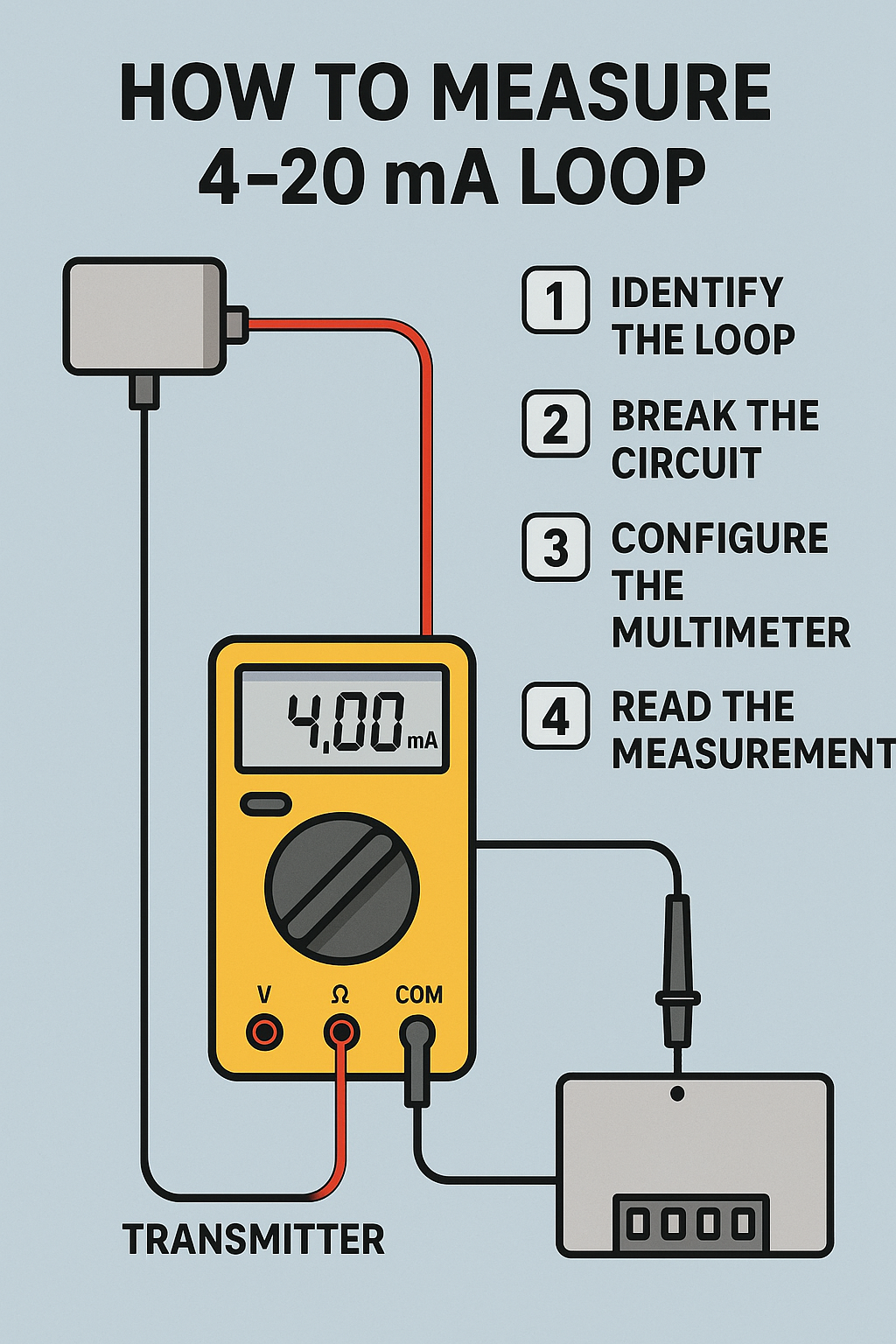
Identify the Loop Wiring
Find the two wires carrying the 4–20 mA signal from the transmitter or sensor to the controller/PLC.
Tip: Consult the device manual or wiring diagram.
Break the Circuit (Series Measurement)
Unlike measuring voltage (parallel), current measurement requires the multimeter to be inserted in series with the loop.
Choose a point where the loop can be safely opened (often at a terminal block or test point).
Power must remain ON in the loop for accurate measurement.
Configure the Multimeter
- Turn the dial to DC mA (usually a 20 mA or 50 mA range is best).
- Plug the red lead into the mA input jack (NOT the voltage or A high-current jack).
- Plug the black lead into the COM jack.
Connect the Multimeter in Series
- Disconnect one wire at the test point.
- Connect the red lead to the wire coming from the transmitter.
- Connect the black lead to the terminal going to the PLC/controller.
- This way, the loop current flows through the meter.
Read the Measurement
A normal signal should read between 4.00 mA and 20.00 mA.
If you see:
- <4 mA → Possible wiring issue, sensor fault, or calibration error.
- >20 mA → Overrange condition or device malfunction.
Remove the Multimeter
Power down or hold the loop signal as needed.
Reconnect the wire directly to restore normal operation.

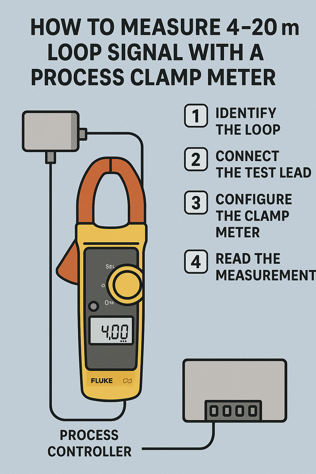
Method #2: Measure the 4-20 mA loop signal with the help of a process clamp meter
The functions of an advanced loop calibrator allow technicians to troubleshoot on the spot without disconnecting wires or “breaking the loop.”
Multifunction process calibrators can also be used to test 4-20 mA loops as well as digital controls.
Step 1: Access the wire connected to the ‘+’ terminal of the transmitter (no need to remove the wire).
Step 2: Put the process clamp meter in ‘Measure’ mode.
Step 3: Clamp the wire connected to the positive terminal of the transmitter and measure the mA signal as shown below.

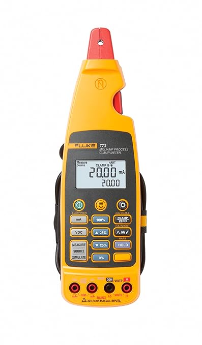
You can use Fluke’s 771 or 772 or 773 process clamp meters to measure mA without breaking the loop.

Advantage of this method
You need not break the loop to measure the mA signal. This is the biggest advantage.
Disadvantage of this method
Process clamp meters are expensive.
Safety Tips when using a multimeter to measure 4-20 mA loop
Check Multimeter Rating
Ensure the multimeter’s current rating is suitable for the expected measurement.
Proper Probe Insertion
Confirm that the multimeter probes are correctly inserted into the appropriate ports (usually labeled COM and mA/µA).
Avoid Overloading
Do not exceed the multimeter’s current measurement limit to prevent damage to the multimeter and ensure personal safety.

Conclusion
Measuring a 4-20 mA signal with a multimeter involves setting the multimeter to the appropriate mode, connecting it in series with the current loop, and interpreting the readings.
This process helps ensure that sensors and transmitters in industrial control systems are operating correctly.
Always prioritize safety by powering down the circuit before making connections and ensuring the multimeter is properly rated for the measurements being taken.
