Reliability of industrial automation still rests on the shoulders of the humble limit switch. In recent years, there has been a rise in advanced proximity and laser sensors.
Nevertheless, the limit switch remains the most trusted device for physical position verification
They ensure safety, accuracy, and repeatability in machines. These machines range from conveyor systems to CNC equipment.
A limit switch provides a clear, deterministic signal. It indicates that a moving part has reached a predefined position.
Unlike noncontact sensors, limit switches rely on physical interaction. This makes them robust even in harsh environments. It also makes them more predictable. Understanding how a limit switch works is essential for engineers.
This article details the construction and operating principle. It also explains the applications and advantages of limit switches. These are relevant in modern industrial systems.
Understanding Limit Switch
A limit switch is an electromechanical device. It is designed to detect the presence or position of an object.
This detection occurs by means of physical contact. When a machine component reaches a specific point, it actuates the switch.
This component may be a cam, lever, or moving carriage. The actuation is mechanical in nature. This action changes the state of the electrical contacts inside the switch.
It sends a signal to a control system. This system may be a PLC, relay logic circuit, or motor controller.
Limit switches are commonly used to:
- Stop motion at the end of travel
- Confirm position or alignment
- Prevent mechanical over-travel
- Initiate a sequence of operations
Their simplicity makes them easy to apply. Their reliability supports long-term operation. Their clear ON/OFF output simplifies control logic. These characteristics make them critical for many industrial uses.

Main Components of a Limit Switch
Limit switches come in many shapes and sizes. However, their internal structure is consistent.
Each component plays a specific role. This role involves converting mechanical motion into an electrical signal.
Actuator (Operating Head)
The actuator is the external part of the switch. It makes contact with the moving object. Common actuator types include:
- Plunger
- Roller lever
- Whisker (spring rod)
- Rotary cam lever
The choice of actuator depends on the motion type. It also depends on speed, accuracy, and durability requirements.
Mechanical Transmission Mechanism
Inside the switch, the actuator connects to a mechanical linkage. It may also connect to a spring-loaded mechanism.
This mechanism ensures that a small external movement is effective. It produces a decisive internal action.
Many limit switches use a snap-action mechanism. This mechanism guarantees fast and consistent contact switching.
Electrical Contacts
The contacts are the electrical heart of the limit switch. They can be:
- Normally Open (NO)
- Normally Closed (NC)
- Changeover (SPDT)
The contact configuration determines circuit behavior. It defines how the control system responds. This response occurs when the switch is actuated.
Housing and Sealing
The housing protects internal components. It shields them from dust and moisture. Also, against oil as well as mechanical damage.
Industrial-grade limit switches often meet IP65 standards. Many also meet IP67 or higher protection ratings.
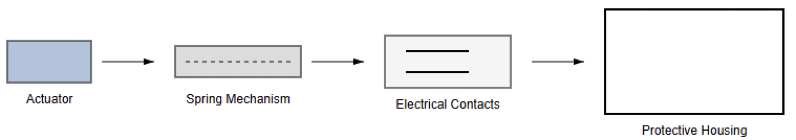
The following figure indicates a diagram of an exploded view of a limit switch showing actuator, spring mechanism, contacts, and housing.
Operating Principle of a Limit Switch
The working principle of a limit switch is mechanical. It is based on displacement leading to electrical switching. This process can be broken down into stages. These stages are clear and repeatable.
When a moving machine part approaches the limit switch, it makes contact. The contact occurs with the actuator.
As the actuator moves, it transfers force inward. This force reaches the internal mechanical mechanism.
Once a predefined travel distance is reached, switching occurs. A force threshold may also trigger this event. The mechanism then produces a snap action.
This snap action changes the state of the electrical contacts. It either opens or closes the circuit.
When the object moves away, the actuator returns. It moves back to its original position under spring force.
The contacts then revert to their normal state. This action is repeatable over time. It allows consistent position feedback. This feedback remains accurate over millions of cycles.
Normally Open and Normally Closed Operation
Understanding contact behavior is essential. It is especially important when designing control circuits.
A Normally Open (NO) contact remains open initially. This occurs when the switch is not actuated. When the actuator is pressed, the contact closes.
This allows current to flow. NO contacts are commonly used for signaling. They are also used for event detection.
On the other hand, a Normally Closed (NC) contact remains closed initially. This occurs when the switch is not actuated.
When the actuator is pressed, the contact opens and interrupts the circuit. NC contacts are widely used in safety circuits. A broken wire results in a safe condition. A failed switch also produces an open circuit.
Many industrial limit switches provide both contact types. They include NO and NC contacts. This offers flexibility in control logic design.
Snap-Action Mechanism
One defining feature of a quality limit switch is the snap-action mechanism. Instead of slow contact movement, it ensures rapid switching. Contacts change state quickly. This occurs once the actuation point is reached.
This behavior provides several advantages:
- Reduced electrical arcing
- Consistent switching point
- Improved contact life
- Reliable operation at low voltages and currents
Snap-action behavior is especially important in control circuits. It supports precise timing requirements.
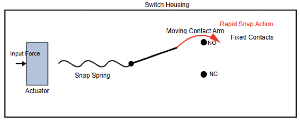
It also maintains signal integrity. The next figure indicates a diagram of an internal snap-action mechanism illustrating rapid contact switching.
Electrical Integration in Control Systems
Limit switches are typically wired into control circuits. These circuits use low-voltage signals. Common values include 24 V DC or 120 V AC. The choice depends on regional standards.
Application requirements also influence the selection. In modern systems, switches connect to PLC digital inputs.
When the limit switch changes state, the PLC detects it. The PLC sees the input transition and then executes programmed logic, such as:
- Stopping a motor
- Reversing direction
- Triggering an alarm
- Initiating the next step in a sequence
In relay-based systems, limit switches control contactors directly. They may also control auxiliary relays.
This approach provides reliable automation logic. It is also straightforward to implement.
Applications of Limit Switches
Limit switches are used across many industries. This is due to their robustness and simplicity. In material handling systems, they detect conveyor endpoints.
They prevent belt overrun conditions. In machine tools, they establish reference positions.
They also prevent axis collisions. Elevators and hoists rely on limit switches. These are used for travel limits and safety interlocks.
In packaging machinery, limit switches ensure proper positioning. They also maintain synchronization of moving parts.
Their ability to function reliably is significant. They work in dusty environments. They also operate in oily and high-vibration conditions. This makes them suitable for industrial use.
Advantages of Using Limit Switches
Limit switches offer several practical advantages. These advantages exceed those of some sensing technologies.
They provide positive mechanical feedback. This ensures the detected position is physically reached.
Their operation is immune to electrical noise. It is also unaffected by optical interference. They are cost-effective solutions, and installation is straightforward. Troubleshooting is simple, and they can operate in extreme temperatures.
They also function in harsh environments. Electronic sensors may fail under these conditions. For safety-related functions, limit switches are preferred.
Their fail-safe wiring options build trust. They are widely accepted in industrial standards. Regulations also recognize their reliability.
Limit Switches vs Non-Contact Sensors
While limit switches are highly reliable, they are not universal. They are not always the best choice. On the other hand, non-contact sensors offer certain advantages.
These include inductive, capacitive, and photoelectric sensors. Such sensors work well in high-speed applications. They also eliminate physical wear.
However, limit switches excel in specific cases:
- Physical confirmation of position is required
- The environment is harsh
- The application demands simplicity and reliability
- Safety circuits are involved
In many systems, both sensor types are used. Limit switches and non-contact sensors complement each other. This balances precision and robustness.
Key Selection Factors
When selecting a switch, consider key variables:
- Environmental Sealing: Does it require an IP67 rating? This is critical for washdown environments.
- Contact Rating: Will it trigger a low-power PLC signal? Or will it control a high-power motor starter?
- Operating Force: How heavy is the target? A glass bottle differs from a steel beam.
- Frequency of Operation: How many times per minute will it actuate? High-speed lines require long-life variants.
Common Failure Modes and Maintenance
Although durable, limit switches can fail. They are not immune to wear. Common issues include mechanical wear of the actuator.
Contact degradation may occur due to arcing. Environmental damage can result from moisture or contaminants.
Preventive maintenance includes:
- Regular inspection of actuator alignment
- Checking contact operation and wiring integrity
- Ensuring proper sealing and mounting
- Replacing switches after their rated mechanical life
Proper installation is critical. Regular maintenance is equally important. Together, they significantly extend operational life.
Conclusion
This article addressed the working principles of limit switches. It also covered construction and practical applications.
Limit switches are fundamental components in automation. They provide reliable and precise position detection.
This is achieved through simple electromechanical principles. By converting physical motion into an electrical signal, they enable safety.
They also support accurate control and effective sequencing. Their snap-action mechanisms improve reliability.
Flexible contact configurations add versatility. Rugged construction supports demanding applications.
Modern non-contact sensors offer advanced capabilities. However, the limit switch remains irreplaceable.
This is especially true in safety-critical environments. Harsh conditions further reinforce their value.
A solid understanding of limit switch operation is essential. It allows engineers and technicians to design reliable systems. It also supports safe and efficient industrial operations.
Frequently Asked Questions
What is a limit switch?
A limit switch is an electromechanical device that detects the presence, absence, or position of a moving part. It changes the state of an electrical circuit when it is actuated by a mechanical force.
How does a limit switch operate?
When a moving machine part contacts the actuator (like a plunger, lever, or roller), it pushes the internal mechanism.
At a certain point, this movement triggers internal contacts to open or close, changing the electrical circuit state. This is often done via a snap-action mechanism for fast and reliable switching.
What triggers a limit switch?
A limit switch is typically triggered by physical contact with a mechanical movement, such as a conveyor item, robot arm, or machine carriage. Some designs also activate through rotational movement or cam engagement.
What are the main contact types in a limit switch?
Limit switch contacts can be Normally Open (NO) or Normally Closed (NC).
- NO contacts close when the actuator is pressed.
- NC contacts open when actuated.
Why do many limit switches use snap-action mechanisms?
Snap-action mechanisms ensure the contacts switch state quickly and cleanly, minimizing electrical arcing and contact bounce. This increases the reliability and lifespan of the switch.
