Remote terminal Unit (RTU), which also stands for Remote Telemetry Unit. It is used to control field devices (sensors, actuators).
This makes them one of the levels of the devices within a Supervisory Control and Data Acquisition (SCADA) system.
RTUs control and monitor field devices through the collection of data from them. Then (as equivalent to PLCs) they convert this data into commands for the actuators, such as pumps and valves.
In this article we are going to explain what RTUs are, their functions, the pros and cons they possess, and how they relate to the future IIoT.
What is A Remote Terminal Unit (RTU)?
A Remote Terminal Unit (RTU) is a microprocessor-based device that is in charge of monitoring and controlling the field devices.
Moreover, they act as an interface between the above-mentioned remote/field and the central station.
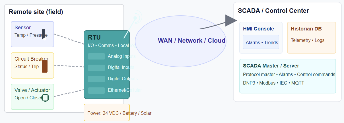
RTUs are more important when it comes to providing real-time data acquisition. And as we know, this is the backbone of an HMI and/or SCADA system. The figure below indicates the position of RTU within the SCADA system

Function of an RTU
- Remote control: Since they are having digital outputs, these allow them to execute commands from the central SCADA system, like any actuators
- Gathering of data: RTUs collect and interpret information coming from different field devices, meters, plus a number of other devices at remote sites. This could be analog and digital data, such as temperature, pressure, or the status of a switch. It depends of what we what to measure and control
- Communication: No doubt RTUs have high capacity of communicating with the central SCADA system, often using various industrial communications protocols.
- Data processing and logging: RTUs can perform some local processing, like calculating accumulated pulses from a meter, and can also log data for later analysis.
- Alarm management: Should not be the less in SCADA system; RTUs also have the ability to detect and report sudden changes or events, such as a sensor exceeding a preset threshold, sending alarms to the central station
Relationship between an RTU and PLC
Fresh engineers, technicians or operation personnel, we mostly have a confusion of what RTUs are and what PLCs are. In this section we will briefly make it clear.
As stated above an RTU and a PLC are both used in industrial controllers, supporting rough environments.
But when it comes to RTUs, they are designed for more remote and long-distance monitoring and data acquisition.
On the other hand, PLCs are built for local real-time control of machines and processes, like directly getting the data from inputs and interpreting them to outputs (actuators). To say so, PLCs are generally used in factories and plants for precise and high-speed tasks.
On the contrary, RTUs are used in distributed and harsh environments like oil fields or water utilities to transmit data back to a central system.
Advantages
Rough environment
RTUs have a high capability to work in harsh conditions, such as high temperature and moisture.
Scalability
One of the characteristics of modern electronics devices/controllers is scalability. This means they must be easily expanded with additional modules and can be integrated into existing systems.
Data logging
This is another important point when it comes to the modern controllers. They must provide continuous data logging with important things like time and date, when alarm was triggered, etc.
Low power consumption
RTUs use automatic cycles as mentioned in the aforementioned point, which makes them well-suited for remote locations where power supply is limited.
Disadvantages
Programming features
Most of the RTU controllers have limited programming features because they are pre-programmed.
Cyber-security
They may be vulnerable to the security due to their connection to HMI and/or SCADA system
Similarities
Although we have mentioned the confusion between the RTUs and PLCs, they both have some features in common. Here are a few that are mentioned
- They both control field devices (sensors and actuators)
- Their input and output modules are somehow similar
- They are both very important to industrial automation
- And not to forget to mention, they are the backbone of SCADA system
Differences
Even if they have a lot of things in common, the big difference between RTUs and PLCs is the purpose of their design
- While PLCs are designed for high-speed, real-time local control, RTUs are for harsh environments.
- PLCs are local controllers, while RTUs are for wide geographical areas
RTU in IIoT
In IIoT the central nodes are important in the ecosystem. So, these RTUs are becoming central nodes in IIoT ecosystems. They integrate with a growing number of devices.
As we are in the age of AI, the recent RTUs are incorporating AI and machine learning for tasks like predictive maintenance and anomaly detection at the edge.
Conclusion
This article explored RTUs: what they are, where they are used, how they function and how they relate to PLCs. It also explained how RTUs are important in industrial automation.
From this, we conclude that the RTUs are essential in our modern industrial automation. This also can mean that they are a very important component in the IIoT.
Without underestimating the PLCs, RTUs are bridging the gap between physical field processes (sensors, actuators) and digital control systems to enhance operational efficiency. Also, the reliability and automation as above were confirmed.
FAQ: What is a Remote Terminal Unit?
What is an RTU?
A field device that collects data from sensors/actuators and sends it to a SCADA system for monitoring and control.
What does an RTU do?
It reads inputs, sends data to a control center, and executes remote commands.
Where is an RTU used?
In utilities and infrastructure: power substations, water systems, pipelines, and remote stations.
How does an RTU communicate?
Via serial, Ethernet, radio, cellular, or fiber links.
What signals can an RTU read?
Digital states (on/off), analog signals (4–20 mA, voltage), and status signals.
Can an RTU control equipment?
Yes. It can open/close valves, start/stop pumps, or operate breakers through its outputs.
How is an RTU different from a PLC?
RTUs focus on remote communication; PLCs focus on fast local control.
Why use an RTU instead of a PLC?
Because it supports long-distance communication, harsh environments, and low-bandwidth links.
Do RTUs support automation logic?
Many modern RTUs include basic logic but not as advanced as PLCs.
What protocols do RTUs use?
Common ones include Modbus, DNP3, and IEC 60870-5-101/104.
Do RTUs work without constant communication?
Yes. They store data and operate autonomously if the link drops.
What power supply do RTUs need?
Typically 24 VDC or battery/solar for remote sites.
Are RTUs rugged?
Yes. They are designed for outdoor, remote, and harsh environments.
Do RTUs support cybersecurity?
Modern RTUs include encryption, user authentication, and secure protocols.
Can RTUs integrate with IoT systems?
Yes. Many support MQTT, cloud gateways, and IIoT platforms.