In industrial automation, Programmable Logic Controllers (PLCs) are vital for managing machines and processes. Among their key functions is counting tracking events, pulses, or signals from inputs.
PLC counters act as digital versions of mechanical tally counters, offering reliable, flexible, and maintenance free control. Unlike mechanical counters, PLC counters operate in software.
This allows precise and programmable logic adaptable to many tasks, such as packaging, material handling, and inventory control.
This article explains what PLC counters are, their types, components, and practical ladder logic examples.
It also highlights advanced features and best practices for ensuring accuracy and efficiency in automated industrial systems.
What is a PLC Counter?
A PLC counter is an internal software instruction used to keep track of the number of times a specific event occurs during a process.
Rather than relying on a physical mechanism with gears or springs, it uses the PLC’s memory to store numerical data that changes according to input signals.
Each time an assigned input changes state from a logic “0” to a logic “1”, the counter either increments or decrements its accumulated value (AV).
When this value reaches a predetermined limit known as the preset value (PV), the counter’s done bit activates.
This “done” condition can then be used to trigger another event in the program. This event could be such as stopping a motor, activating an alarm, or initiating another machine cycle.
By performing counting functions in software, PLC counters ensure precision and repeatability.
They are easy to configure for different operations such as batch production, product tracking, or sequential control.
They are also highly reliable because they have no moving parts. This means they are not affected by wear or vibration, problems that often occurred with older mechanical counters.
In short, a PLC counter serves as a digital event tracker, allowing a system to respond automatically once a specific number of occurrences is detected.
Types of PLC Counters
PLCs typically include three main types of counters, each suited to a particular kind of counting behavior:
Count-Up (CTU) Counter
- Function: The CTU counter increases its stored or accumulated value by one every time the assigned input transitions from false to true.
- Operation: As pulses are received, the counter continues to increment until its accumulated value equals or exceeds the preset number set by the programmer. Once this happens, the counter’s done bit (DN) is activated and can trigger another output or sequence.
- Reset: The counter can be reset at any moment using its reset input, which clears the accumulated value back to zero.
- Application Example: Suppose a conveyor belt system needs to count 10 items before activating a packaging robot. Each time a sensor detects an item, the CTU counter increases by one. Once the total reaches ten, the done bit becomes true, signaling the robot to pick up the batch and start the packaging cycle.
Count-Down (CTD) Counter
- Function: The CTD counter performs the opposite task—it decreases its accumulated value by one each time an input pulse is detected.
- Operation: This type of counter is usually initialized with a preset value and counts down toward zero. When the accumulated value reaches zero, the counter’s done bit is set to true, signaling completion.
- Load/Preset: Instead of a basic reset, CTDs often include a load (LD) input that reloads the preset value into the counter at the start of each new cycle.
- Application Example: Imagine a dispenser containing 50 parts. The counter starts at 50 and decreases each time an item is released. When it reaches zero, the done bit activates a warning light or alarm to indicate the container is empty and needs refilling.
Count-Up/Count-Down (CTUD) Counter
- Function: A CTUD counter combines the functions of both CTU and CTD. It can increase or decrease the same accumulated value depending on which input (up or down) receives a pulse.
- Operation: The counter adds one count whenever the “up” input is activated and subtracts one count when the “down” input is triggered. Both inputs share the same memory location, which makes it ideal for processes that require two-way counting.
- Application Example: Consider a parking garage that can hold 100 vehicles. A sensor at the entrance adds one count when a car enters, while a sensor at the exit subtracts one when a car leaves. The current value of the counter shows how many spaces are occupied. When the count reaches 100, the done bit triggers the “Lot Full” indicator.
Main Components of a PLC Counter
Although their specific implementation may differ among PLC brands, all counters have a common structure consisting of several key parts:
- Counter Address or Tag: The unique identifier for the counter within the PLC program (e.g., C5:0 in Allen-Bradley PLCs).
- Preset Value (PV): The target or limit that determines when the counter’s done bit should activate.
- Accumulated Value (AV): The running count that changes as the input pulses occur. For CTU counters, it starts at zero; for CTD counters, it usually begins at the PV.
- Done Bit (DN): A status flag that becomes true when the AV meets the preset condition.
- Count-Up (CU) and Count-Down (CD) Inputs: The terminals or logical inputs that receive external pulses from sensors or switches.
- Reset (R) or Load (LD): Inputs used to clear or reload the counter’s AV.
These elements make it easy for engineers to configure, monitor, and debug counting functions directly within the PLC software interface.
PLC Counter Examples Using Ladder Logic
Ladder Logic is the most widely used PLC programming language. This is because its visual structure resembles traditional electrical circuits, making it intuitive for technicians and engineers.
The following examples demonstrate how counters are typically implemented.
Example 1: Simple Count-Up Application (Part Counting)
Scenario: A machine must fill a box with 10 parts before sealing it. Each time a part is detected by a proximity sensor, the PLC increments a counter.
Logic: A CTU counter is programmed with a PV of 10. When the AV reaches this value, the DN activates the sealing mechanism.
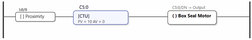
Explanation:
The sensor sends a pulse every time a part enters the box, increasing the counter by one. Once the counter reaches 10, the DN energizes the output coil controlling the box-seal motor.
Example 2: Count-Down Application (Dispenser Control)
Scenario: A dispenser holds 25 items, and each item dispensed should reduce the count. When the counter reaches zero, a refill indicator turns on.
Logic: A CTD counter with a preset of 0 and an initial accumulated value of 25 is used.
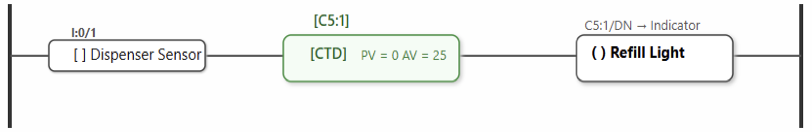
Explanation:
Every time an item is dispensed, the sensor sends a pulse that decreases the accumulated value by one. When the counter reaches zero, the DN energizes the refill light, prompting an operator to restock the dispenser.
Example 3: Count-Up/Down Application (Parking Garage)
Scenario: A garage accommodates 100 cars. The system must track entries and exits to display a “Lot Full” signal when the capacity is reached.
Logic: A CTUD counter is used, with one sensor connected to the count-up input (entrance) and another to the countdown input (exit).
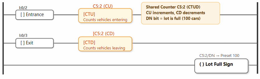
Explanation:
Each incoming car triggers the count up input; each departing car triggers the countdown input.
When the counter equals the PV of 100, the DN activates the “Lot Full” sign. When cars exit, the counter decreases accordingly, automatically turning the sign off.
Advanced Counter Concepts
Cascading Counters
When a single counter cannot handle very large numbers due to memory limits, multiple counters can be connected or cascaded.
The done bit of one counter acts as the input pulse for the next, effectively multiplying their counting capacity.
For example, cascading two counters each preset to 100 can extend the range up to 10,000 counts (100 × 100).
This approach is useful in applications such as production line totals or large-scale event monitoring.
High-Speed Counters (HSCs)
Standard PLC counters operate based on the PLC’s scan cycle. If input pulses occur faster than the scan rate, some may be missed.
To handle high-frequency signals, many PLCs offer High-Speed Counter (HSC) modules.
These modules process inputs directly through dedicated hardware, bypassing the main CPU to ensure no pulses are lost.
HSCs are essential for applications where precision timing and fast response are critical.
Examples of these applications are encoder feedback, speed measurement and/or motion control.
Best Practices for Using PLC Counters
Simulate Before Deployment
Test all counter logic in a simulation environment before implementing it in a real system to detect logic or wiring mistakes early.
Manage Reset Logic Carefully
Ensure that counters only reset when appropriate conditions are met, such as when a new production batch begins.
Use Descriptive Names
Assign meaningful tags such as Bottle_Count or Parts_Total to make the program easier to understand and maintain.
Prevent Overflows and Underflows
Always verify that the counter’s accumulated value stays within its valid range to avoid errors.
Use Suitable Hardware
When dealing with fast pulses or encoder signals, use high-speed counter modules to maintain accuracy.
Document Your Program
Include comments that describe each counter’s purpose and preset values to assist future troubleshooting or system updates.
Key Takeaways: PLC Counters
This article explained what PLC counters are and described their types and components.
It also presented real-life ladder logic examples. PLC counters are essential and versatile tools in modern industrial automation.
They form the foundation for many control tasks, from simple part counting on assembly lines to complex batch control operations.
By learning how to use CTU, CTD, and CTUD counters, engineers can design reliable and efficient automation systems.
Understanding their internal components and applying them correctly in ladder logic ensures error-free performance.
Modern PLCs now include High-Speed Counters and advanced communication features.
These improvements expand the use of precise counting in industrial systems. As automation grows more data-driven, accurate counting becomes increasingly important.
In today’s factories, the PLC counter remains a key element, ensuring every pulse, product, and process is tracked with precision.
FAQ: PLC Counters Explained
What is a PLC counter, and what are its basic parts?
A PLC counter is a software instruction that tracks pulses or events.
Main parts:
– CU/CD inputs: count up or down.
– PV: preset value or target count.
– CV/AV: accumulated value.
– Reset/Load: clear or set a starting value.
– Done bit: activates when preset is reached.
What types of PLC counters are there?
– CTU: counts up (e.g., parts on a conveyor).
– CTD: counts down (e.g., items remaining).
– CTUD: counts up and down (e.g., parking lot cars).
What are limits and overflow/underflow?
Each counter has max/min limits. Too many pulses can cause overflow or missed counts.
How does reset or load work?
Reset clears the count; Load sets an initial value.
What’s the difference between “normal” vs “high-speed” counters?
Normal counters rely on scan time; high-speed ones handle fast pulses independently.
How do counters behave on first scan or power-up?
Counters usually start at 0 (CTU) or PV (CTD). Some retain memory after power loss.
How do I ensure counting is accurate (i.e., avoid false/multiple counts)?
Use edge detection, debounce sensors, and ensure reset conditions are correct.
What happens when the preset value is changed during operation?
Altering PV during operation may instantly activate the done bit or need reset.
Can counters count negative values?
Some PLCs allow negative counts; others stop at zero.
Are there practical examples or applications of counters in industry?
Used for part counting, inventory tracking, maintenance cycles, and quality control.
What are status bits like overflow, underflow, done, etc.?
– DN: done.
– Overflow/Underflow: count exceeds limits.
– CU/CD: indicate direction of counting.
What features differ across brands / manufacturers?
Vary by count range, memory retention, speed, and handling of reset/load or high-speed features.
