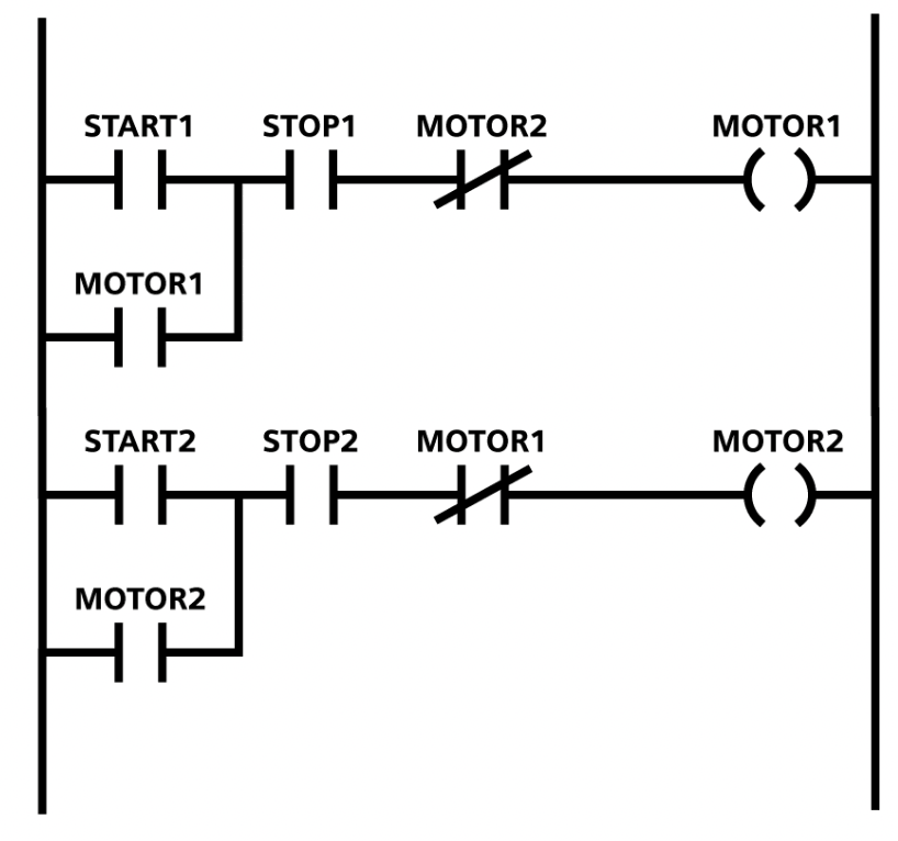
If you’ve ever looked at a PLC program and thought it looked like a ladder someone drew sideways, you weren’t far off.
Ladder logic is the most widely used programming language for industrial automation, and once you understand the handful of symbols that make it up, you can read and write programs that control everything from a conveyor belt to a bottling line.
This guide walks through ladder logic from the ground up: what it is, why it exists, how to read a rung, and how to build your first simple programs. No prior programming background required.
What Is Ladder Logic?
Ladder logic is a graphical programming language used to program programmable logic controllers (PLCs).
It’s called “ladder” logic because a program looks like a ladder: two vertical rails on the left and right represent the power supply, and horizontal lines between them called rungs represent individual control circuits.
Ladder logic was created in the 1960s to replace hardwired relay panels. Electricians who were used to reading relay schematics could look at a ladder diagram and immediately understand the logic, without learning a traditional text-based programming language.
That design goal is still the reason ladder logic dominates the factory floor today: it’s visual, it maps closely to physical wiring, and it’s easy to troubleshoot with the PLC connected live.
Why Ladder Logic Still Matters in 2026
Text-based PLC languages like Structured Text have grown more popular for complex logic, and even runtime environments have shifted (see our guide on virtual PLCs for how execution is changing).
But ladder logic remains the default language taught in technical schools, required on most ISA and vendor certification exams, and still the first language any new automation technician encounters on a plant floor.
If you’re planning a career in industrial automation, whether as a PLC programmer or an automation engineer, ladder logic fluency is non-negotiable.
The Basic Building Blocks
Rails and Rungs
Every ladder diagram has two vertical rails: the left rail (power) and the right rail (return/neutral).
Between them run horizontal rungs, each representing one independent piece of logic. The PLC scans every rung from top to bottom, left to right, dozens or hundreds of times per second. This is called the scan cycle.
Contacts (Inputs)
Contacts represent input conditions, switches, sensors, or internal bits and are drawn as two vertical lines.
| Symbol | Name | Meaning |
|---|---|---|
—| |— | Normally Open (NO) contact | Passes power when the input is TRUE/energized |
—|/|— | Normally Closed (NC) contact | Passes power when the input is FALSE/de-energized |
Coils (Outputs)
Coils represent outputs, things the PLC turns on or off, like a motor starter, solenoid, or indicator light. They’re drawn as a circle or parentheses at the end of a rung.
| Symbol | Name | Meaning |
|---|---|---|
—( )— | Output coil | Energizes the output when the rung is TRUE |
—(/)— | Negated output coil | De-energizes the output when the rung is TRUE |
—(L)— | Latch coil | Turns output ON and keeps it on until unlatched |
—(U)— | Unlatch the coil. | Turns a latched output OFF |
Timers and Counters
Timers delay an action; counters track how many times an event happens. The two most common timer types are the following.
- TON (Timer On-Delay): starts timing when the rung goes true. The output turns on after the preset time elapses
- TOF (Timer Off-Delay): output turns off only after the preset time elapses once the rung goes false
Counters (CTU for count-up, CTD for count-down) increment or decrement a value each time the input transitions from false to true, commonly used to count parts on a line.
How to Read a Rung: A Simple Example
Here’s a single rung in plain terms.
|--[ ]----------[ ]--------------( )--|
   Start   E-Stop(NC)    Motor
This reads as if the Start pushbutton is pressed AND the E-Stop is not tripped, energize the motor coil. Contacts wired in series on the same rung act as an AND condition. Contacts wired in parallel branches act as an OR condition.
Building a Seal-In (Latching) Circuit
One of the first real circuits every beginner builds is a seal-in circuit, the ladder logic equivalent of “press to start, stays on until you press stop.” It’s the foundation of motor control logic.
|--[ ]-------[/]-----------------( )--|
   Start    Stop              Motor
|--[ ]------------------------------|
   Motor (parallel branch around Start)
Here, a second contact referencing the Motor output is wired in parallel with the Start contact.
Once Motor energizes, that parallel contact keeps the rung true even after the operator releases the Start button.
The circuit “seals itself in.” Pressing Stop breaks the rung and drops the Motor output out. This single pattern shows up, in some form, in nearly every real-world PLC program.
Common Beginner Mistakes
- Confusing NO and NC contacts: an E-Stop is almost always wired normally closed, so the PLC sees it as “true” when the button is not pressed. Beginners often flip this logic by accident.
- Forgetting the scan cycle: the PLC doesn’t run rungs continuously like a spinning motor; it scans top-to-bottom repeatedly. Logic that depends on rung order (like using an output before it’s set) can cause a one-scan delay.
- Overusing latches without unlatch logic: a latched coil with no corresponding unlatch condition will stay on forever, even after a power cycle on some platforms.
- Not simulating before downloading: Most PLC software (Studio 5000, TIA Portal, CODESYS) offers an offline simulation mode. Test logic there before pushing to a live controller.
Ladder Logic vs. Other PLC Languages
| Language | Best For | Learning Curve |
|---|---|---|
| Ladder Logic (LD) | Discrete control, motor/relay logic, troubleshooting on the floor | Low |
| Structured Text (ST) | Math-heavy logic, loops, complex algorithms | Medium-High |
| Function Block Diagram (FBD) | Process control, PID loops | Medium |
| Sequential Function Chart (SFC) | Step-by-step sequences, batch processes | Medium |
Most modern PLC platforms let you mix languages within one project, for example, ladder logic for I/O handling and structured text for a calculation-heavy subroutine.
If you want to go deeper on structured text once ladder logic clicks, see our guide on structured text examples.
Where to Practice
You don’t need a physical PLC to start learning. Most major vendors offer free or trial simulation software:
- Rockwell Automation: RSLogix Emulate / Studio 5000 with the emulator
- Siemens: TIA Portal with PLCSIM
- CODESYS: free IDE with a built-in soft-PLC simulator, vendor-agnostic
Start by rebuilding the seal-in circuit above from scratch, then add a timer so the motor stops automatically after a set time.
Small, self-contained exercises like this build real fluency faster than reading theory alone.
Frequently Asked Questions
Is ladder logic hard to learn?
No, of all PLC languages, ladder logic has the lowest learning curve because it visually mirrors physical relay wiring.
Most beginners can read basic rungs within a few hours and write simple motor control logic within a week of practice.
Do I need to know electronics to learn ladder logic?
A basic understanding of relay logic and electrical circuits helps, but it’s not mandatory. Understanding series (AND) and parallel (OR) contact wiring covers most of what you need to get started.
What’s the difference between a PLC and ladder logic?
A PLC (Programmable Logic Controller) is the hardware device that controls machinery. Ladder logic is one of several programming languages used to write the instructions that run on that hardware.
Can I learn ladder logic for free?
Yes. CODESYS offers a free IDE with a soft-PLC simulator, and Siemens and Rockwell both offer trial versions of their software with simulation modes, so you can practice without buying a physical PLC.
Is ladder logic still used in 2026?
Yes. Despite growth in structured text and the emergence of virtual/soft PLCs, ladder logic remains the standard entry-level language across the industry and is still required knowledge for most automation and controls roles.
Want to see ladder logic applied to real production scenarios? Check out our companion guide, Ladder Logic Examples: 25 Programs Explained, for worked examples across motor control, conveyor sequencing, and safety interlocks.
