What is Commissioning in Industrial Automation?

Hardware, software, and communication networks are integrated into industrial automation systems for organized production settings.

Programmable logic controllers control operator interfaces, drives, actuators, and sensors over large buildings. 

Before manufacturing operations start, these linked components must run flawlessly. Commissioning is the systematic process by which one checks readiness for safe operation.

Hidden wiring mistakes and config mismatches go undetected without consistent inspection. 

If preparation is inadequate, issues often arise during the first energizing. Engineers, hence, conduct rigorous testing before operational release. Thorough documentation underpins long-term upkeep planning as well as traceability. 

Effective commissioning greatly lowers costly downtime and startup delays. This article reviews commissioning principles, stages, documentation practices, and verification methods in industrial automation projects.

What is Commissioning in Industrial Automation?

Commissioning in industrial automation bridges installation activities and formal operational handover.

It confirms that the equipment performs according to approved engineering specifications and functional descriptions. 

The process usually validates electrical connections. It also verifies software configuration as well as mechanical integration comprehensively.

Engineers ensure that safety interlocks operate correctly under simulated abnormal conditions. Performance tests evaluate control response, stability, and deterministic execution. 

What is Commissioning in Industrial Automation?


Structured Workflow of Commissioning in Industrial Automation Systems

Communication networks are examined to confirm reliable data exchange between devices.

Calibration activities guarantee accurate measurement signals from instruments. Without commissioning, latent defects frequently appear during production runs. 

Such failures can risk safety and quality. At the same time, it endangers productivity. Therefore, commissioning protects both technical integrity and financial investment.

Pre-Commissioning Activities

Pre-commissioning begins once physical installation activities reach completion. Visual inspections verify proper equipment placement and mechanical fastening integrity. Technicians compare cable terminations carefully against approved wiring diagrams. 

Continuity tests confirm conductor routing and electrical correctness. Insulation resistance measurements detect potential wiring degradation or moisture ingress. Protective grounding connections are verified for safety compliance. 

Power supplies undergo preliminary energization without connected process loads. Panel labeling and device identification are reviewed systematically.

Software backups are prepared before applying full system power. These structured inspections create confidence before dynamic testing begins.

Loop Checking and I/O Verification

Loop checking validates each field signal path from the sensor to the controller. Engineers simulate transmitter outputs at instrument locations to confirm accuracy.

PLC input channels must display corresponding measured values within tolerance limits. 

Analog outputs are verified using calibrated measurement instruments. Digital outputs are tested by controlled actuation of field devices. Each loop receives documented approval signatures after successful verification. 

Incorrect scaling, polarity inversions, or wiring swaps become evident immediately. Signal instability or electrical noise may also appear during testing.

Early detection prevents extensive troubleshooting during integrated startup. Detailed loop records simplify future maintenance interventions significantly.

PLC Program Validation

Control logic must reflect the approved functional design documentation precisely. Engineers review ladder diagrams, function blocks, or structured text code carefully. Simulation environments assist preliminary validation before hardware energization occurs. 

For example, platforms like Siemens TIA Portal provide integrated tools for configuration and testing.

Hardware configuration parameters are compared against actual installed modules. Input and output addressing must correspond exactly with wiring schedules. 

Timers, counters, and sequencing logic undergo verification under realistic scenarios. Alarm handling routines are evaluated for correct prioritization and annunciation. Program validation ensures stable and predictable plant behavior during operation.

Human Machine Interface Testing

Operators depend on human-machine interfaces for daily plant supervision. Screens must display accurate real-time values from process equipment. Alarm banners require clear categorization and acknowledgment mechanisms. 

Trend displays help evaluate performance over defined time intervals. User permission structures prevent unauthorized parameter modifications.

Testing verifies correct tag mapping between PLC variables and interface objects. For example, FactoryTalk View integrates visualization functions with controller data effectively. 

Communication delays are measured to confirm acceptable responsiveness. Graphical indicators must represent actual equipment states consistently. Effective interface testing increases operator confidence during initial startup.

Network and Communication Verification

Modern automation relies heavily on deterministic industrial communication networks. Ethernet-based infrastructures connect controllers, drives, and remote input modules. Protocols such as PROFINET enable structured data exchange between distributed devices.

Commissioning verifies correct IP addressing and network topology configuration. Managed switch settings are inspected for redundancy and segmentation features. Network load analysis identifies potential congestion risks early. 

Communication loss scenarios are intentionally simulated under controlled conditions. Controllers must transition safely during temporary network interruptions. Reliable connectivity ensures coordinated and integrated plant operation.

Functional and Integrated Testing

Functional testing validates complete process sequences under realistic conditions. Engineers execute start and stop procedures repeatedly to observe consistency. Interlocks are tested under abnormal or faulted scenarios deliberately. 

Emergency stop circuits receive prioritized verification attention. System-level testing verifies coordinated operation between mechanical, electrical, and control software components. Motors, valves, and drives operate in coordinated production cycles. 

Process variables are monitored closely for stability and oscillation. Response times are compared carefully with design expectations.

Stakeholders review performance results during structured evaluation meetings. Successful integrated testing confirms readiness for operational release.

Safety and Compliance Verification

Safety systems require rigorous and well-documented validation procedures. Protective relays undergo dedicated functional testing sequences.

A similar process takes place for safety PLCs. The International Electrotechnical Commission has standards that guide compliance verification.

Lockout mechanisms must function correctly during simulated maintenance scenarios. Safety instrumented functions are tested under representative fault conditions. Redundant channels require independent confirmation of operational integrity.

Risk assessments are updated following observed testing outcomes. Commissioning documentation demonstrates regulatory compliance to auditors. Safety verification ultimately protects personnel and valuable equipment assets.

Documentation and Handover

Commissioning generates comprehensive technical documentation for future reference. Test reports record measured values, observations, and corrective actions. As-built drawings reflect final installation and configuration conditions. 

Software archives are stored securely for disaster recovery purposes. Calibration certificates accompany critical measurement instruments. Operators receive structured training on system functionality and alarms. 

Maintenance staff learn systematic troubleshooting and diagnostic procedures. Final acceptance tests confirm contractual and performance requirements clearly. Structured handover marks the transition toward routine plant operation.

Commissioning Within Industry 4.0 and IIoT

Modern commissioning increasingly supports digital transformation initiatives. Concepts associated with Industry 4.0 emphasize connectivity.

It also highlights data analytics and intelligent automation. Reliable commissioning ensures sensors and controllers deliver trustworthy data to higher-level platforms.

Within Industrial Internet of Things architectures, validated devices become networked information sources.

Proper testing guarantees cybersecurity configurations and communication reliability. Therefore, commissioning establishes the technical foundation for smart, connected, and data-driven industrial operations

Conclusion

This article introduced commissioning principles within industrial automation environments.

It described preparatory inspections, loop verification, and software validation practices. Network testing, safety compliance, and integrated functional checks were examined. 

The importance of structured documentation and collaborative teamwork was emphasized.

Commissioning was presented as a disciplined and methodical engineering activity. Its contribution to safety, reliability, and predictable performance was highlighted clearly. 

Without comprehensive commissioning, operational instability and hidden defects may persist.

A systematic approach transforms complex installations into dependable production systems.

Effective commissioning ultimately safeguards investments and ensures sustainable industrial operation.

FAQs

What is Commissioning in Industrial Automation?

Commissioning is the methodical procedure that confirms all automation equipment and control systems operate as planned before entering service. It moves a project from implementation to safe operating readiness. 

What phases define commissioning? 

Pre-commissioning inspections and cold testing. It also consists of hot testing under actual loads, functional tests, safety verification, and final handover of papers, which usually comprise these. 

Is commissioning limited just to mechanical devices? 

No, commissioning also confirms control systems, programmable logic controllers, communication networks, and safety interlocks. End-to-end system validation is the aim. 

Who ought commissions to be done by? 

Commissioning should be carried out by qualified technicians and engineers with experience in electrical systems.

Automation and control knowledge is a plus. Critical tests should not be carried out by unauthorized workers. 

Which papers are created throughout commissioning? 

Commissioning procedures, test results, wiring paperwork, acceptance reports, and employee training logs are among the usual deliverables. 

Automation: What is virtual commissioning? 

 Virtual commissioning helps to reduce errors and save time by using digital twins to simulate and verify control logic and system behavior before the actual system is put in.


What is loop checking, and why is it important?

Dependable signal transmission across complicated buildings and precise instrumentation are really important for industrial automation systems.

Coordinated regulatory structures comprising sensors, transmitters, controllers, and final control elements are created by control loops.

Each loop must function precisely within defined operational and safety boundaries at all times.

Even minor wiring mistakes or configuration mismatches can generate serious startup disruptions. Improper scaling or polarity errors may create unsafe operating conditions quickly. 

Loop checking is the structured verification process performed before full commissioning activities begin.

It ensures that every signal path operates according to approved engineering documentation. 

Technicians validate measurements, signal continuity, and actuator responses under controlled testing conditions.

This disciplined procedure reduces uncertainty during plant energization and startup phases.

This article reviews the principles of loop checking and explains why it remains essential for safety, reliability, and successful commissioning.

Understanding Loop Checking

Loop checking is a systematic commissioning activity conducted after installation completion.

It focuses on verifying the integrity of individual instrumentation control loops. A control loop generally includes measurement, transmission, processing, and actuation components. 

These components must operate together without signal distortion or interruption. Signals may be analog, digital, or discrete types depending on application requirements. Analog loops often use standardized four-to-twenty milliamp signals. 

Digital loops may use network-based industrial communication protocols. During loop checking, technicians apply known reference signals carefully.

The control system reading is compared against expected engineering values. Output commands are issued from controllers to final elements. 

Valves, relays, and motors must respond proportionally and correctly. Any deviation between expected and actual behavior requires investigation.

This structured verification confirms alignment between design documentation and field installation. It bridges the gap between construction activities and operational readiness.

Components Involved in Loop Checking

Every instrumentation loop contains interconnected electrical and mechanical components.

The primary sensing element measures process variables such as pressure or temperature. A transmitter converts the measured variable into electrical signals. 

These signals travel through electric cables. Also, they run across junction boxes and even terminal panels.

Proper shielding and grounding practices must be verified during inspection. Within the control system, input modules receive transmitted signals accurately. 

The controller processes data according to programmed logic sequences. Output modules generate commands toward the final control devices. Final elements may include control valves, dampers, or motor starters. 

Loop checking verifies continuity between every terminal connection point. Channel assignments must match engineering drawings and tag lists.

Human-machine interface displays should present correct process values. Alarm thresholds and scaling parameters require careful validation.

The following figure illustrates the complete signal path within a typical instrumentation control loop.

It visually demonstrates how a physical process variable is measured by a sensor. Then converted into an electrical signal by a transmitter.

Furthermore, it is transmitted through wiring infrastructure, processed by the controller, and finally used to actuate a control element.

The diagram supports the discussion by showing why every connection point must be verified during loop checking.

It emphasizes that a failure at any stage can compromise overall system performance and safety.

Typical Instrumentation Control Loop Architecture

Procedure for Performing Loop Checking

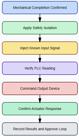
Loop checking begins only after confirming mechanical installation completion. Instruments must be mounted securely and identified clearly with tags. All cables should be terminated according to approved wiring diagrams. 

Commissioning teams prepare detailed loop check sheets before testing begins. These documents reference signal ranges, alarm limits, and device addresses. Safety permits and isolation procedures must be implemented properly.

Technicians connect calibrated simulation equipment to transmitter circuits. A known test signal is injected into the loop wiring.

The corresponding value displayed in the control system is observed. Differences indicate configuration errors or calibration discrepancies immediately. 

Necessary adjustments are performed to correct identified deviations. Output testing is followed by issuing commands from the control interface.

Actuators must respond correctly to varying signal magnitudes. Valve stroke position or motor rotation confirms mechanical functionality. 

Feedback signals are compared with commanded values carefully. All results are recorded systematically on verification documentation sheets. Only successfully validated loops proceed toward integrated functional testing.

The logical order followed during loop checking exercises is shown by this diagram. It logically structures the verification procedure from installation confirmation up to signal simulation, system validation, actuator response testing, and paperwork. 

The flowchart draws attention to the systematic nature of loop checking as well as the decision points needing corrective action.

Visual representation of the workflow helps to clarify the figure and backs up the procedural explanation given in the book.

Loop Checking Verification Workflow

Importance of Loop Checking in Safety

Safety considerations make loop checking critically important in industrial environments. Many facilities are likely to handle high pressures.

In addition, they manage extreme temperatures and hazardous materials. Incorrect measurement signals may disable protective shutdown functions unintentionally. 

Reversed polarity wiring could prevent emergency interlocks from activating. Misconfigured alarms might fail during abnormal operating conditions.

Loop checking ensures protective devices operate exactly as engineered. Safety instrumented functions depend on precise and reliable signal transmission. 

Verification reduces risks associated with human installation errors significantly. Regulatory authorities frequently require documented commissioning evidence for approval.

Inspection bodies review loop check records during compliance audits. Comprehensive verification strengthens overall plant safety management strategies.

Operational Reliability and Performance Benefits

Accurate control depends on stable and verified measurement signals. Wiring faults can introduce noise and distort transmitted values.

Incorrect scaling may produce oscillatory or unstable control behavior. Loop checking eliminates many hidden uncertainties before startup. Controllers receive validated data for precise regulation actions.

Stable signals improve product quality and process consistency. Energy consumption decreases when control loops operate efficiently. Verified baseline readings support future troubleshooting and diagnostics.

Maintenance teams benefit from documented commissioning reference values. This structured verification approach enhances long-term operational reliability.

Loop checking also reduces unplanned downtime during early operation. Early detection of faults prevents costly production interruptions later.

Contractors and clients both benefit from minimized startup risks. The time invested in verification yields significant operational returns.

Common Errors Detected During Loop Checking

Loop checking frequently uncovers wiring termination mistakes in panels. Crossed conductors may connect signals to incorrect controller inputs.

Open circuits can interrupt signal transmission completely. Short circuits may damage sensitive input modules permanently. Incorrect terminal labeling complicates future maintenance activities unnecessarily.

Configuration errors also appear during systematic verification procedures. Engineers may enter incorrect measurement ranges during setup.

Unit conversion mistakes distort displayed engineering values significantly. Digital systems sometimes experience duplicate device addressing conflicts. 

Incorrect network parameters can disrupt communication reliability. Identifying these issues before dynamic startup prevents costly delays.

Equipment damage risks decrease when faults are corrected early. Thorough verification, therefore, protects both schedule and investment.

Relationship with Commissioning and Startup

Loop checking represents a major milestone within the project commissioning phases. It is typically completed before integrated functional testing begins.

Verified loops provide confidence in instrumentation signal integrity. Without this validation, system-level tests may produce misleading results.

Startup teams rely heavily on accurate instrumentation feedback. Operators must trust displayed values during initial energization.

Incorrect readings can lead to improper operational decisions quickly. Loop checking builds confidence among engineers and plant operators.

Early detection of discrepancies reduces rework during critical schedules. Projects progress more smoothly when loops are validated systematically. Effective loop checking contributes directly to successful plant startup.

Conclusion

This article introduced the concept of loop checking and described its structured verification process in industrial automation projects.

It explained how individual instrumentation loops are validated before commissioning and startup activities begin. 

The discussion highlighted safety benefits, operational reliability improvements, and common errors detected during verification.

Loop checking ensures alignment between engineering documentation and physical installation conditions. 

Confirming signal integrity lessens starting risks and avoids expensive operating interruptions.

Published verification also meets regulatory compliance requirements and quality assurance needs.

In the end, regular loop checking boosts trust in control systems and encourages secure, effective, and dependable industrial activities.

FAQs


What is loop checking?

It is the verification activity that confirms a control loop’s complete signal path functions correctly from sensor to controller and back. 

When is loop checking performed?

Loop checking is carried out after installation and wiring of instruments, but before full system commissioning begins. 

What components are tested during a loop check?

Verification procedures confirm the accuracy and continuity of field instruments, cabling, junction points, and control elements. 

Why is loop checking important?

It ensures measurements, signal continuity, and configuration are correct, preventing unsafe conditions and startup failures. 

Does the loop checking test alarms and trips?

Yes, loop checks often include verifying alarm, trip, and interlock signals at the control system. 

Is loop checking the same as a function test?

No, loop checking verifies signal integrity, whereas function testing validates control logic and actual process responses. 

Can loop checks detect wiring mistakes?

Yes, loop checking is specifically designed to uncover wiring errors. It is also in charge of discovering polarity issues and termination faults. 

What types of signals are checked?

Analog signals like 4–20 mA, digital communications, and discrete on/off signals can all be included in loop checks. 

Is loop checking only done on new installations?

No, loop checking may also be done during maintenance, upgrades, or after repairs to ensure ongoing system integrity. 

What documentation supports loop checking?

Loop diagrams, P&IDs, cable schedules, tag lists, and formal check sheets are commonly used as references.

How Analog Signal Noise Affects PLC Systems

Industrial automation systems rely heavily on accurate measurement data to maintain stability. It also counts on efficiency and safety across complex processes.

Programmable logic controllers continuously process signals received from numerous field instruments distributed throughout industrial facilities. 

Many of these signals are transmitted as low-level analog values representing physical quantities.

Temperature, pressure, flow, and level sensors commonly provide such continuous measurement signals.

These measurements directly influence control decisions, alarm thresholds, and protective shutdown actions. 

However, industrial environments are electrically noisy by nature and rarely electrically quiet.

High-power equipment generates disturbances that can couple into adjacent signal wiring unexpectedly.

Electromagnetic interference may distort sensitive analog measurements significantly and unpredictably. 

Even minor distortion can propagate through control algorithms and affect final outputs. Engineers must therefore understand how analog noise influences PLC systems comprehensively.

This article investigates fundamental principles, industrial causes, system impacts, and practical mitigation strategies.

Understanding Analog Signals in PLC Systems

Analog signals represent continuously varying physical process quantities measured over time within industrial installations. They differ fundamentally from discrete digital signals that only indicate binary states. 

PLC analog input modules typically accept standardized voltage or current ranges from sensors.

Common voltage standards include zero to ten volts for instrumentation signals. Current loop standards frequently use four to twenty milliamps for industrial transmitters.

Current loops generally provide better immunity to electrical interference compared to voltage signals.

Inside the PLC, analog modules convert incoming electrical signals into digital values using analog-to-digital converters.

Resolution determines the smallest measurable increment change that the system can detect reliably. 

Sampling time influences how accurately dynamic variations are captured and represented internally.

Stable signal representation depends strongly on electrical integrity throughout the transmission path.

When noise contaminates the signal, the digital representation no longer reflects the true process variable accurately.

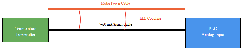
Analog signal transmission path with electromagnetic noise coupling from adjacent power conductors

Nature and Sources of Analog Signal Noise

Analog signal noise consists of unwanted electrical disturbances superimposed onto the intended measurement waveform.

These disturbances may appear as random fluctuations or periodic oscillations within the signal. 

Electromagnetic interference represents a primary noise source in industrial facilities containing heavy equipment.

Large induction motors generate strong magnetic fields, especially during startup and load transitions.

Variable frequency drives emit high-frequency switching harmonics due to rapid semiconductor switching events.

Contactors and relays create transient voltage spikes whenever mechanical contacts open or close abruptly.

Improper grounding schemes introduce ground loop currents that circulate between different potential references. 

Long cable runs may behave like unintended receiving antennas for external electromagnetic fields. Power conductors routed near signal cables induce capacitive or inductive coupling effects. 

Radio frequency transmitters and wireless devices can inject additional interference components.

Thermal noise also originates within electronic circuitry components inherently. Each noise source contributes uniquely to the overall level of signal degradation.

Impact on Measurement Accuracy and Resolution

Noise introduces unwanted fluctuations into measured analog values processed by PLC systems.

These fluctuations distort the true magnitude of the physical process variable. High-resolution input modules become particularly sensitive to small disturbances present in the signal. 

Small amplitude noise may, therefore, appear as meaningful variation in displayed values. Operators might interpret these oscillations as genuine process instability conditions.

Control strategies depend on accurate and stable feedback signals for proper performance.

Erroneous measurements lead to inappropriate corrective control actions within closed-loop systems. 

Derivative control terms amplify high-frequency noise components significantly during operation. As a consequence, actuator commands may oscillate excessively without actual process change. 

Mechanical wear increases due to unnecessary movement and repetitive actuation cycles. Measurement uncertainty also complicates calibration procedures and optimization efforts across industrial plants.

Influence on Closed-Loop Control Performance

Closed-loop control systems rely on precise and trustworthy feedback signals continuously.

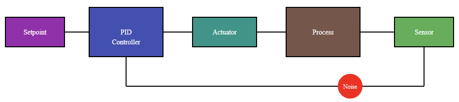
Noise effectively behaves as an external disturbance input entering the feedback path. The controller attempts to compensate for perceived deviations from the setpoint value. 

When deviations originate from measurement noise, corrective actions become unnecessary and counterproductive. Repeated compensation may produce oscillatory control behavior known as limit cycling.

Limit cycling reduces overall process efficiency and negatively affects energy consumption performance. Integral control action may accumulate error introduced purely by noise components. 

Integrator windup increases overshoot during transient responses following disturbances. Settling time exceeds the originally designed or tuned specifications.

Engineers may incorrectly adjust controller gains while attempting to correct noise symptoms.

Such improper tuning decisions can further degrade overall system stability unintentionally.

Closed-loop control system showing measurement noise injected in the feedback path

Effects on PLC Hardware and Diagnostics

Persistent electrical noise can stress sensitive analog input circuitry components over extended periods.

High-amplitude transient spikes risk damaging internal protection networks and isolation stages.

Repeated electrical stress reduces the long-term reliability of analog modules significantly. 

Intermittent faults may appear within diagnostic logs without obvious physical causes. Technicians might suspect sensor malfunction or wiring faults incorrectly during troubleshooting activities. 

Troubleshooting time increases because symptoms do not reflect the actual root causes clearly.

Spurious alarms triggered by noisy measurements reduce operator confidence in instrumentation systems. Operators may gradually ignore alarm messages, including legitimate warnings. 

Data historians store corrupted measurement values for long-term analysis purposes. Historical trends become unreliable for performance evaluation and root cause investigations. System credibility declines among production and maintenance teams gradually.

Noise Propagation Across Automation Architectures

Analog noise effects do not remain confined to a single PLC input channel. Once converted into digital values, distorted data propagates through communication networks.

Supervisory control systems and human-machine interfaces rely on transmitted measurements. 

Distorted data influences higher-level optimization and scheduling algorithms negatively.

Distributed control architectures amplify localized disturbances across interconnected controllers.

Shared variables may destabilize coordinated sequences between multiple control units. Batch processes become inconsistent under fluctuating feedback conditions. 

Energy monitoring systems may miscalculate consumption patterns due to inaccurate sensor inputs.

Predictive analytics platforms receive misleading trend information that compromises reliability.

Thus, localized analog noise can create broader system-wide consequences beyond initial measurement distortion.

Engineering Techniques for Noise Mitigation

Proper grounding establishes the primary reference necessary for controlling electrical noise.

Single-point grounding minimizes unwanted circulating currents between equipment frames.

Shielded cables reduce susceptibility to external electromagnetic interference significantly. 

Cable shields must terminate properly at defined grounding points to function effectively. Twisted pair conductors reduce differential mode interference through magnetic field cancellation principles. 

Physical separation between power and signal wiring remains a fundamental installation requirement.

Proper cable routing avoids proximity to high current conductors and switching devices. 

Signal isolation modules break conductive noise paths between field devices and controllers.

Optical isolation enhances protection against voltage transients and ground potential differences. 

Analog filtering attenuates high-frequency disturbances before digital conversion occurs. Software-based filtering complements hardware mitigation measures within PLC programs.

Recommended analog signal wiring and isolation architecture for noise mitigation in PLC systems

Digital Filtering and Signal Conditioning

Digital filtering processes sampled signals using mathematical algorithms executed by the PLC processor.

Moving average filters reduce random noise variations through successive value averaging techniques. 

Exponential smoothing filters balance responsiveness with effective signal stabilization performance.

However, excessive filtering introduces undesirable time delay effects within control loops.

Time delay reduces responsiveness and may degrade dynamic control performance noticeably.

Engineers must evaluate appropriate filter time constants carefully during commissioning phases. Signal amplification increases the signal-to-noise ratio for weak sensor outputs. 

Proper scaling ensures accurate numerical representation within PLC memory registers. Calibration establishes reliable baseline references for measurement integrity.

Periodic verification maintains long-term stability of signal conditioning performance. Combined conditioning strategies enhance overall system robustness and measurement fidelity.

Practical Industrial Design Considerations

Industrial facilities present challenging electromagnetic environments requiring disciplined engineering practices. Design must anticipate worst-case interference scenarios realistically and conservatively. 

Control panel layout significantly influences internal coupling between power and signal circuits.

Analog modules should be physically separated from high-power switching components. Dedicated instrumentation power supplies improve the stability of sensitive measurement systems.

Routine inspection prevents the gradual degradation of grounding and shielding connections.

Commissioning tests should explicitly evaluate susceptibility to electrical interference conditions. Monitoring scan times and signal trends may reveal abnormal fluctuations early.

Proper training increases understanding of interference sources and appropriate mitigation techniques.

Comprehensive documentation of wiring practices aids future troubleshooting and maintenance activities.

Proactive noise management ultimately supports reliable automation performance and long-term operational stability.

Conclusion

This article introduced the mechanisms through which analog signal noise affects PLC systems and industrial control reliability.

It explained how electrical disturbances distort measurement accuracy and digital representation integrity. 

The discussion examined consequences for control stability, hardware reliability, and diagnostics systematically.

Broader system-wide impacts across communication and supervisory layers were clarified. 

Practical grounding, shielding, isolation, and filtering techniques were described in detail. Digital conditioning strategies were analyzed alongside realistic industrial design considerations. Industrial environments will always contain potential interference sources that challenge signal integrity. 

Engineers must therefore prioritize disciplined installation practices and thoughtful configuration decisions.

Proper noise mitigation leads to control actions that are accurate, feedback loops that are stable, and the operation of the plant is safe.

Knowing such principles, one can design automation systems that are not only resilient and dependable but also of high performance.

FAQs

In a PLC system, what constitutes analog signal noise? 

Unwanted electrical interference, known as analog signal noise, distorts the actual analog measuring signal before it gets to the PLC input. 

How is noise vulnerable to analog signals? 

Analog circuits have continuously changing values; thus, low-level voltages or currents can readily pick up electrical noise from nearby appliances or wiring. 

What common equipment generates noise in industrial environments?

Heavy motors, variable frequency drives, contactors, and high voltage cables are typical noise sources that inject interference into analog lines. 

How does noise enter the analog signal cable?

Acting like an antenna, a signal cable can pick up coupled noise when it passes by magnetic sources or power cables.

What visible effect does noise have on PLC analog readings?

Even when the process is steady, noise can cause measured value jitter, spikes, or random variations.

.

What is a Watchdog Timer in PLCs?

Industrial automation systems demand reliability, determinism, and operational safety at every operational level.

Programmable Logic Controllers operate under strict real-time execution constraints in industrial environments. 

Unexpected software faults can jeopardize entire production processes. It also endangers the critical assets.

Electrical disturbances and electromagnetic interference may also disrupt normal program execution unexpectedly. 

Engineers therefore implement mechanisms that detect abnormal execution states before consequences escalate. One essential mechanism integrated into modern controllers is the watchdog timer. 

This internal component continuously supervises the program scan cycle duration and CPU responsiveness.

If execution exceeds configured limits, protective actions activate immediately and predictably. 

Such supervision prevents uncontrolled machine behavior and unsafe operating conditions.

It also improves maintainability and diagnostic transparency across industrial facilities. This article reviews fundamental principles, implementation details, configuration strategies, and practical engineering considerations.

Understanding the PLC Scan Cycle

To understand watchdog timers properly, the PLC scan cycle must first be examined carefully. A PLC executes instructions in repetitive, deterministic loops throughout operation. 

Each loop typically follows three structured operational phases in sequence. First, input modules update internal memory registers with field device states. Second, the CPU processes the user control program instructions logically. 

Third, output modules update field devices according to calculated results. This repetitive execution sequence is known as the scan cycle.

Scan time depends on program size, instruction type, and communication load. Under stable conditions, scan duration remains predictable and consistent. 

However, abnormal logic structures can extend processing time unexpectedly. Infinite loops or excessive computation may delay scan completion dangerously.

These abnormal timing conditions require automatic detection and corrective action. The watchdog timer performs this continuous supervisory monitoring function reliably.

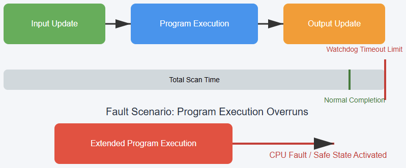
The following figure illustrates the PLC scan cycle sequence and watchdog supervision clearly.

It shows input update, program execution, and output update blocks sequentially. A timing bar represents the total scan duration measurements.

The watchdog timeout limit defines the maximum allowed execution time. When execution overruns this boundary, a CPU fault condition activates.

What Is a Watchdog Timer in PLCs?

A watchdog timer is a supervisory timing mechanism embedded within the PLC architecture. It monitors whether the CPU completes each scan cycle within a predefined time limit. 

The timer measures elapsed execution time during program processing continuously. If execution finishes within configured limits, the timer resets automatically. If limits are exceeded, a fault condition is triggered intentionally. 

This protective response may halt program execution to prevent unsafe continuation. In many PLC platforms, outputs transition into predefined safe states immediately. A diagnostic fault code is usually generated for troubleshooting purposes. 

Maintenance personnel can then analyze logs to determine the root cause systematically. The watchdog therefore acts as a safety sentinel within the control system. Without such supervision, runaway code could cause severe equipment damage.

Hardware and Firmware Implementation

Watchdog timers may be implemented in dedicated hardware circuitry or embedded firmware routines. Hardware watchdogs operate independently of the main processor logic circuitry. 

This independence ensures detection even during severe processor malfunction conditions.

Firmware watchdogs, by contrast, integrate closely with the controller operating system. 

Both approaches aim to detect unresponsive CPU behavior consistently and deterministically.

In advanced controllers, layered watchdog architectures provide enhanced reliability. One layer supervises the application program scan time specifically. 

Another layer monitors the operating system kernel’s responsiveness separately. Such redundancy supports compliance with functional safety standards.

Controllers developed under IEC 61508 incorporate deterministic fault detection principles.

These design requirements strengthen system integrity under abnormal operating scenarios.

Configuring Watchdog Time Parameters

Proper watchdog configuration requires careful engineering judgment and measurement. Setting the timeout value too low can cause nuisance trips frequently. Conversely, setting it excessively high reduces protective effectiveness significantly.

Engineers typically measure worst-case scan time under maximum load conditions. Communication overhead and interrupt routines must be considered during evaluation. Complex arithmetic operations or data logging tasks may increase execution duration. 

Many PLC platforms provide diagnostic tools displaying maximum observed scan times. Systems from Siemens include diagnostic buffers and timing statistics for analysis. 

Controllers from Rockwell Automation similarly report CPU load and scan metrics. Using these measurements, engineers define safe margins above the expected execution time. Clear documentation of selected thresholds supports future maintenance activities.

Causes of Watchdog Faults

Watchdog faults frequently indicate underlying programming or hardware issues. Infinite loops within ladder logic commonly trigger timeout conditions. Uncontrolled recursion or excessive iteration can exhaust processor resources rapidly. 

Heavy communication retries may delay scan completion beyond acceptable limits. Faulty input modules sometimes block data exchange operations unexpectedly. Electrical noise may corrupt memory transactions under harsh industrial conditions.

Firmware anomalies can also result in processor lockups, but rarely. Large data handling routines may overload CPU capacity during peak operations.

Each of these conditions extends execution time beyond configured thresholds. The watchdog timer detects these abnormal durations and initiates a protective response.

Watchdog Response and Safety Considerations

When the watchdog limit is exceeded, predefined safety actions execute immediately. Most PLCs transition into a fault state requiring operator intervention. Outputs typically deenergize to ensure machines enter safe conditions. 

Alarm systems may activate to notify operators and supervisors promptly. Human machine interfaces display diagnostic messages for troubleshooting guidance. After corrective actions, controllers usually require a manual reset before restarting. 

Automatic restart strategies must undergo careful safety evaluation before implementation. Watchdog timers support functional safety objectives within industrial control systems. 

Systems aligned with ISO 13849 require validated timing behavior documentation. Nevertheless, watchdogs do not replace emergency stop circuits or hardware interlocks. They supervise software execution timing rather than mechanical hazard mitigation directly.

Practical Engineering Perspective

From a practical engineering standpoint, watchdog tuning often requires iterative refinement.

During commissioning, engineers monitor scan time fluctuations under realistic operating conditions. 

Segregating heavy calculations into periodic tasks can reduce primary scan duration. Structured and modular programming improves determinism and maintainability considerably. 

Eliminating unnecessary nested logic enhances performance predictability significantly. In applications involving motor drives or power electronics converters, CPU freezes may cause costly damage. 

A properly tuned watchdog provides an essential protective software layer. This layer complements hardware protections such as circuit breakers and interlocks. Thoughtful configuration reflects professional engineering responsibility and foresight.

Conclusion

This article introduced the watchdog timer as a critical supervisory mechanism within PLC systems. It explained how scan cycles determine execution timing and operational predictability. 

The discussion described hardware and firmware implementation approaches clearly. Configuration strategies were examined alongside common fault causes systematically. 

Functional safety standards provided contextual relevance for industrial environments. Practical engineering considerations highlighted commissioning and maintenance realities effectively.

The limitations and misconceptions regarding watchdog functionality were clarified carefully. 

Ultimately, watchdog timers improve system reliability by quickly identifying abnormal execution delays.

Proper configuration balances responsiveness with operational stability requirements. Engineers who understand watchdog principles design safer and more resilient automation systems

FAQs

In a PLC, what is a watchdog timer? 

 It is a timing system that checks PLC scan or task run and spots execution delays or faults. 

 PLCs employ watchdog timers for what reasons? 

 PLCs employ them to guard the system and identifyproblems,s including frozen logic or infinite loops. 

 How does a watchdog timer work in a PLC? 

 The PLC routinely refreshes the timer while running normally. If it doesn’t reset it in time, a fault occurs. 

 When the watchdog timer runs out, what transpires? 

 Usually, the PLC halts execution, enters a fault condition, and could compel outputs to a secure state. 

 What typical problems result in watchdog failures? 

 Hardware interrupts, ineffective code, and infinite loops can increase scan time past the watchdog constraint. 

 Is the watchdog timer adjustable? 

 On several PLC systems, watchdog timeouts are customizable to correspond with anticipated scan times. 

 Does the watchdog timer replace safety devices? 

 No, a watchdog helps with software security but does not take the place of mandated hardware safety devices like E-STOP circuits. 

 How is the watchdog timer set? 

 Usually, it is set based on worst-case scan time plus a margin to prevent pointless false alarms. 

 Can a watchdog reset the PLC automatically? 

 Some systems may initiate a reset or safe shutdown upon timeout. 

 Using a watchdog timer mostly serves what purpose? 

 By finding errors early and stopping uninvited behavior, it improves system dependability.

PLC Troubleshooting Methodology Step by Step

Programmable logic controllers represent a vital part of the automation setup not only in industries but also worldwide.

They work together with machines, process flows, and safety features in a variety of sectors. 

When PLC systems fail, production losses and safety risks quickly increase significantly. Therefore, a structured troubleshooting methodology becomes critical for reliable operations. Random guessing wastes time and may introduce additional faults.

In troubleshooting, engineers’ diagnostic approaches need to be disciplined, repeatable, and technically sound.

Successful troubleshooting is a mixture of electrical knowledge, process understanding, and logical reasoning skills. 

On top of that, it requires maintaining accurate records and following the steps of verification in a systematic way each time.

It also demands careful documentation and systematic verification steps consistently. A clear methodology reduces downtime and improves maintenance efficiency considerably. 

PLC Troubleshooting Methodology Step by Step

Technicians gain confidence when following organized diagnostic procedures daily. This article explains step-by-step PLC troubleshooting methodology principles.

Step 1: Understanding the Problem Clearly

The first step involves clearly defining the observed problem precisely. Symptoms must be described accurately without assumptions or speculation. Operators should explain what the machine is doing incorrectly now. 

Service logs often highlight recurring faults or hidden trends. Always determine whether the issue is electrical, logical, or mechanical. A machine not starting differs from incorrect sequence execution behavior. 

Clarifying scope prevents unnecessary modifications to unrelated control sections. Good troubleshooting begins with careful listening and direct observation. Accurate problem statements guide the entire diagnostic process effectively.

The following diagram visually represents the logical decision-making path used during PLC troubleshooting.

It emphasizes sequential validation of power, hardware, and software before implementing corrective actions. 

The flowchart reinforces disciplined thinking and reduces the likelihood of unnecessary component replacement or incorrect program modifications

Flowchart of PLC Troubleshooting (step by step) 

Step 2: Our Safety and Proper Preparation

Be sure to fully and strictly comply with all safety measures, first of all, if you are going to do diagnostic work.

Lockout and tagout are the ways used to protect workers from the hazard of getting an unexpected energization. Personal protective equipment must match the system voltage levels present.

Never bypass safety circuits without authorized risk assessment documentation. Review electrical drawings and control schematics thoroughly beforehand. Confirm the correct PLC model and firmware version identification clearly. 

Verify available programming software matches the controller requirements exactly. Preparation minimizes risk and prevents avoidable configuration errors later. Organized preparation establishes professional discipline in maintenance activities.

Step 3: Verifying Power Supply and Hardware Status

Many PLC issues originate from simple power problems frequently. Check the incoming supply voltage using calibrated measurement instruments properly. Confirm correct voltage levels at PLC power terminals directly. 

Inspect power supply modules for overheating or visible damage signs. Observe status LEDs indicating healthy or fault conditions carefully. A flashing error LED often signals configuration or hardware issues. 

Loose terminal connections frequently cause intermittent system behavior problems. Grounding integrity should also be verified carefully and methodically.

Stable power conditions form the foundation for reliable operation. Hardware verification eliminates many common faults early and quickly.

Step 4: Checking Input Devices and Field Signals

After confirming power integrity, examine input devices systematically. Verify sensors receive proper operating voltage from control panels consistently. Use multimeters to measure actual input signal states accurately.

Observe PLC input indicator LEDs for state changes visually. If an input never activates, inspect wiring continuity carefully. Broken conductors commonly occur near moving mechanical assemblies. 

Confirm the correct sensor type and wiring configuration carefully. Compare field wiring with electrical schematics meticulously and patiently.

Incorrectly wired inputs often mimic complex logical faults misleadingly. Reliable inputs are essential for correct control decisions.

The next diagram illustrates the complete signal path from a field sensor to the final actuator. It helps engineers and technicians understand different important points. These include where to measure voltage, observe LED indicators, and isolate faults. 

By visually separating field devices, wiring, and PLC modules, the diagram clarifies how input problems differ from output or logic-related issues.

Step 5: Evaluating Output Devices and Actuators

Outputs must be tested methodically after validating inputs completely. Check output indicator LEDs within the PLC module first. If the LED activates but the device remains off, suspect wiring issues. 

Measure output voltage at terminal blocks carefully using instruments. Inspect contactors, relays, and solenoids for mechanical sticking conditions. Overloaded outputs may trigger protection circuits internally sometimes. 

Confirm output type matches device electrical characteristics exactly. Never connect inductive loads without proper suppression components installed.

Hardware validation eliminates confusion before software analysis begins logically. Functional outputs confirm that commands reach physical equipment reliably.

Step 6: Reviewing PLC Program Logic Step by Step

Once hardware integrity is confirmed, analyze program logic carefully. Open the ladder diagram or relevant programming language environment. Follow signal flow from inputs toward final outputs sequentially. 

Use online monitoring tools to observe rung execution status. Identify whether conditions evaluate as true or false unexpectedly.

Force inputs cautiously only when safe and authorized officially. Examine timers and counters for unexpected accumulated values carefully. 

Incorrect preset values frequently cause sequence delays unexpectedly. Look for overwritten variables or duplicate memory addresses systematically.

Logical errors often stem from misunderstood process requirements originally. Structured analysis prevents unnecessary code modifications impulsively.

Step 7: Investigating Communication and Network Issues

Modern PLC systems commonly communicate over industrial networks extensively. Check communication status indicators on network modules carefully. Verify correct IP addresses and network configuration parameters accurately. 

Loose Ethernet connectors frequently disrupt communication reliability significantly. Inspect network switches for port status abnormalities immediately. Confirm protocol compatibility between PLC and remote devices clearly. 

Review diagnostic buffers for communication timeout messages consistently. Network faults can appear as unpredictable machine behavior symptoms. Reliable communication ensures that coordinated distributed control functions properly.

Step 8: Analyzing Interlocks and Safety Circuits

Interlocks frequently prevent equipment from starting intentionally for safety. Review safety relays and emergency stop circuits carefully always.

Confirm safety contacts are closed under normal conditions consistently. A single open interlock may block entire sequences unexpectedly. 

Check guard switches and limit switches’ alignment precisely. Safety PLCs may require separate diagnostic evaluation procedures.

Never bypass safety logic without formal authorization approval. Understanding interlocks prevents misdiagnosing functional protections as faults.

Step 9: Executing Fixes and Verifying Performance

After identifying the root cause, plan corrective action methodically. Avoid making multiple simultaneous changes during repairs unnecessarily. Implement one modification and retest system operation carefully. 

Document each change clearly within maintenance records immediately. Replace defective components using approved specifications precisely. Update program comments if logic modifications occur properly. 

Confirm that system performance matches the original design requirements fully. Run the machine through complete operational cycles carefully.

Observe performance under normal load conditions attentively. Thorough verification ensures fault elimination without introducing new errors.

Conclusion

This article clarified the systematic methodology for troubleshooting PLC systems step by step.

Structured approaches significantly reduce downtime and operational uncertainty effectively. Beginning with a clear problem definition prevents misguided repair attempts entirely.

Verifying power, inputs, and outputs establishes hardware reliability first. Logical program analysis follows only after confirming electrical integrity.

Communication networks and safety interlocks require equal diagnostic attention always. 

Careful corrective actions and thorough verification ensure lasting solutions consistently. Consistent documentation supports future maintenance efficiency improvements significantly. A disciplined mindset ultimately defines successful PLC troubleshooting practice.

Frequently Asked Questions

Why check the power supply first? 

A lot of times, power problems cause PLCs to fail; hence, having a stable voltage and good grounding will save you from many troubles. 

How important are input and output checks?

Very. Verifying I/O modules, sensors, and actuators ensures the PLC receives and sends correct signals. 

When do I cash in on the PLC program logic review?

Once you have made sure that the hardware is okay, you can now check and trial the program sequences and logic for possible errors. 

What steps should I take if communication breaks down? 

Look for the network cables, connectors, and configurations to bring the communication between the devices and the PLC back.

How can diagnostic tools assist in troubleshooting? 

Employ the use of onboard diagnostics, status LEDs, and software logs to locate the fault really fast.

What is the reason behind most of the time PLC throwing errors apart from wiring and power? 

Defective I/O modules, dirty code, and environment (heat, dust) are the usual suspects of the PLC.

Is looking at a scene helpful during problem troubleshooting?

Indeed, your eyes will show you the way. A glance will confirm if there is anything such as cables broken, connections loose, or a component heated up.

How Does a Proximity Sensor Work

Industries such as automation and robotics use proximity sensors. Without forgetting consumer electronics and safety systems. Proximity sensors are different from mechanical switches. 

This is because the object can be detected without physical contact. Hence, reliability and longevity are improved.

They are widely used for position sensing and object counting. Also, for speed detection and safety interlocks. 

It is necessary to examine their operating principles and sensing technologies. Then this helps to understand how proximity sensors work. It also requires understanding application-specific behaviors. 

This article explains the fundamental working mechanisms of proximity sensors. It explores the major types used in industry. It also highlights their advantages, limitations, and applications.

What is a proximity sensor?

Just like other sensors, a proximity sensor is an electronic device designed to detect an object within a defined range.

It functions without physical contact. It does not rely on mechanical movement. It uses electromagnetic fields or light. Also, on sound waves or capacitance.

These methods allow the sensor to sense objects. When a target enters the sensing zone, the sensor generates an electrical signal. This signal can be used for control, monitoring, or safety purposes.

Proximity sensors are commonly found in industrial automation systems and conveyor lines.

They are also used in machine tools, mobile phones, automotive systems, and building automation. 

Their contactless operation makes them ideal for harsh environments. These environments include dust, moisture, vibration, or frequent switching. Such conditions would quickly degrade mechanical sensors.

How Does a Proximity Sensor Work?

At a fundamental level, all proximity sensors follow the same basic process. First, a sensing field or signal is generated by a sensor. This may be an ultrasonic wave, light beam, or electromagnetic field. 

Next, an object enters this field. The object causes a measurable change. This change may be reflection, absorption, disturbance, or attenuation.

Finally, the sensor’s internal electronics detect this change. The change is converted into an electrical output signal.

The nature of the sensing field determines the sensor’s classification. The type of interaction with the object also determines classification. These factors define performance characteristics.

Key Components of a Proximity Sensor

Although designs vary, most proximity sensors include several common internal components.

The sensing element generates and monitors the sensing field. The signal processing circuit amplifies the detected signal. It also conditions the signal. 

A comparator or threshold circuit determines significance. It decides whether the change indicates object presence.

Finally, an output stage provides a usable signal. This may be a digital ON/OFF output or an analog signal.

Some proximity sensors include indicator LEDs. They may also include temperature compensation circuits.

Protection features are often included. These include short circuit or reverse polarity protection.

Inductive Proximity Sensors

Working Principle

These sensors are used to detect metallic targets. They operate based on electromagnetic induction.

Inside the sensor, an oscillator generates a high-frequency magnetic field. This field is alternating in nature.

It is produced through a coil at the sensing face. When a metal object enters this field, eddy currents are induced.

These currents form on the surface of the object. The eddy currents create an opposing magnetic field. 

This field reduces the amplitude of the original oscillation. The sensor’s electronics monitor this reduction.

The sensor switches its output state once the oscillation drops below a predefined threshold.

The following figure illustrates an inductive proximity sensor showing coil and magnetic field lines. Also, it indicates a metal target and eddy current formation.

Characteristics

Inductive sensors are highly reliable. They are immune to dirt, oil, water, and non-metallic materials. However, their sensing range is relatively short. The range depends on the type of metal. 

Ferromagnetic materials such as steel are detected at longer distances. Non-ferrous metals include aluminum or copper. These are detected at shorter distances.

Capacitive Proximity Sensors

Working Principle

Through measuring changes in capacitance, objects are detected by these sensors. The sensor consists of a sensing electrode.

It also includes a reference electrode. Together, they form a capacitor. The surrounding environment acts as the dielectric medium.

When an object approaches the sensing face, it alters the dielectric constant. This occurs within the sensing field.

The change increases the capacitance. The sensor’s internal oscillator detects this change. The processing circuit evaluates it. If capacitance exceeds the preset limit, the sensor output changes.

Characteristics

Capacitive sensors can detect metallic objects. They can also detect non-metallic objects. These include liquids, plastics, powders, and grains. They are commonly used for level detection. 

This occurs in tanks and silos. However, environmental factors are a challenge to them. These include humidity and dust, without forgetting temperature changes. Finally, periodic recalibration is also necessary.

Photoelectric Proximity Sensors

Working Principle

Photoelectric sensors use light to detect objects, which is typically infrared or visible. A light emitter sends a beam toward a target area. A receiver detects the light. The presence of an object alters the received light. 

This occurs through interruption, reflection, or diffusion. There are three main photoelectric sensing modes.

In through-beam mode, the object blocks the light. The light travels between a separate emitter and receiver. 

In retro-reflective mode, light reflects off a reflector. It returns to the sensor unless interrupted by an object.

In diffuse mode, the object itself reflects light. The light is reflected back to the receiver.

Characteristics

Photoelectric sensors offer longer sensing distances. These distances exceed those of inductive and capacitive types. They can detect very small objects.

They work with a wide range of materials. However, performance can be affected by dust. Ambient light can also affect performance. Surface reflectivity of the target is another factor.

Ultrasonic Proximity Sensors

Working Principle

These sensors operate using high-frequency sound waves. Human hearing is far beyond these waves.

Initially the sensor uses its transmitter to emit an ultrasonic pulse. It then waits for the echo. The echo is reflected by an object. 

The time delay is measured. This delay occurs between transmission and reception. It is converted into distance.

The conversion uses the speed of sound. The sensor output is activated when the measured distance falls within a preset range. 

This time-of-flight principle allows accurate distance measurement. It works regardless of object color. It also works regardless of object transparency.

Characteristics

When it comes to detecting transparent objects, then ultrasonic sensors are the choice. Examples include glass or clear plastic.

These objects are challenging for optical sensors. Ultrasonic sensors are widely used for level measurement.

However, air temperature can affect sound propagation.  Not only turbulence but also humidity has influence to accuracy.

Magnetic Proximity Sensors

Working Principle

Magnetic proximity sensors detect magnetic fields. These fields are generated by permanent magnets or electromagnets. Common implementations include reed switches. Hall-effect sensors are also used. 

When a magnetic field approaches the sensor, it causes a change. This change occurs in electrical behavior. It may close a reed contact. It may also alter the voltage output of a Hall-effect element.

Characteristics

Magnetic sensors are simple and robust. They are well suited for position detection. Common uses include doors, cylinders, and rotating machinery.

Their operation depends on the presence of a magnet. This requirement may limit some applications.

Output Types and Signal Processing

Proximity sensors typically provide digital outputs. They may also provide analog outputs. Digital outputs indicate a simple ON or OFF state. This occurs when an object is detected. Analog outputs provide a continuous signal. 

The signal is proportional to distance or signal strength. Common output configurations include NPN and PNP. Normally open and normally closed outputs are also used.

Signal processing ensures noise immunity. It provides stable switching. It ensures repeatable performance. This is important in electrically noisy industrial environments.

Advantages of Proximity Sensors

One primary advantage of proximity sensors is non-contact operation. This eliminates mechanical wear. They offer fast response times.

They also provide high repeatability. Long service life is another benefit. Proximity sensors improve safety. 

They enable contactless detection. This is useful in hazardous areas. Their versatility allows use across many industries.

These include manufacturing and packaging. Automotive and consumer electronics are also included.

Limitations and Selection Considerations

Each sensing technology has constraints. These relate to range and material compatibility. Environmental sensitivity is also a factor. Proper selection requires careful consideration. 

Target material must be evaluated. Sensing distance is important. Mounting conditions must be considered. Temperature range and output type are also critical.

Understanding the working principle helps engineers choose correctly. It allows selection of the most suitable sensor. This ensures proper application performance.

Industrial and Everyday Applications

In industrial automation, proximity sensors are used for object counting. They are also used for position detection.

Speed monitoring is another application. Machine safety is equally important. In robotics, they assist with obstacle detection. 

They also support accurate positioning. In consumer electronics, they enable screen wake-up features. Touchless controls are also supported. Automotive systems rely on proximity sensors. 

They are used for parking assistance. Door detection is another use. Engine position sensing is also common.

Their widespread use highlights their importance. They are essential in modern technology.

Key Takeaways: How Does a Proximity Sensor Work

The present article detailed the fundamental working mechanisms of proximity sensors. It studied the major types used in industry. It also showed their advantages, limitations, and applications.

From the afore mentioned we can say that proximity sensors play a vital role in modern systems. They enable reliable and contactless detection.

They generate a sensing field. They detect how objects interact with it. These sensors convert physical presence into electrical signals. 

Different types exist. These include inductive and capacitive. Plus, photoelectric, ultrasonic, and magnetic sensors.

Each uses distinct physical principles. Understanding how proximity sensors work allows effective selection. 

It also supports correct application and maintenance. As automation continues to evolve, proximity sensors remain fundamental. They are key building blocks in sensing technology. 

FAQ: How Does a Proximity Sensor Work

What is a proximity sensor?

A proximity sensor is a device that detects the presence or absence of an object without physical contact. It constantly emits a field or signal and senses changes caused by nearby objects. 

How does a proximity sensor detect objects?

It emits a signal (magnetic field, electric field, light, or sound) and monitors changes in that signal when an object enters its detection range. 

What kinds of signals do proximity sensors use?

Different types use electromagnetic fields (inductive), electric fields (capacitive), infrared/visible light (photoelectric), or sound waves (ultrasonic) to detect objects. 

Do proximity sensors need physical contact to work?

No, they detect objects without touching them, which reduces wear and increases lifespan. 

Can proximity sensors detect all types of materials?

It depends on the type:

  • Inductive: best for metal.
  • Capacitive: can sense metal and non-metal like plastic or liquid.
  • Ultrasonic and photoelectric: can detect a wide range of materials.

How to Learn PLC Programming

In the modern world, industrial automation and Programmable Logic Controllers (PLCs) play a critical role.

Their main applications are controlling machines, manufacturing lines, and industrial processes. These processes not only run with high reliability but also with high precision. 

PLCs are designed to interact directly with real equipment. This means learning PLC programming requires more than just writing code. It involves understanding electrical systems, control logic, and industrial practices. 

Beginners often feel overwhelmed by hardware concepts and vendor-specific software environments. This article explains how PLC programming can be learned step by step.

It starts from fundamental principles and gradually progresses. It moves toward practical, real-world applications used in industry today.

What is a PLC, and what does it do?

Before proceeding to the learning process, first, we should ask what a PLC actually does. A PLC is an industrial computer designed to monitor input signals. It executes a control program and updates output signals continuously. 

This process happens in a repetitive loop known as the PLC scan cycle. During each scan, the controller reads the status of sensors and switches. It processes the logic written by the programmer. 

It then sends a command to the outputs. This command is used to energize or de-energize actuators such as motors, valves, or indicator lamps. A clear understanding of the PLC’s internal structure is essential at this stage. 

The PLC consists of a power supply and a central processing unit (CPU). It also includes input modules, output modules, and communication interfaces. Visualizing how these components interact helps beginners. 

It helps them connect abstract logic to physical equipment. The next figure illustrates a basic PLC block diagram. It shows CPU, power supply, input modules, output modules, and field devices.

Learning Electrical and Control Fundamentals

PLC programming is closely tied to electrical control systems, and ignoring this foundation leads to confusion later.

Before writing programs, learners should understand how basic electrical components behave. 

Traditional relay-based control systems are particularly important. PLC ladder logic was designed to replicate relay wiring diagrams.

This replication occurs in software form. When you understand how push buttons, contacts, relays, and contactors work, ladder logic becomes intuitive.

Instead of memorizing symbols, you begin to recognize familiar electrical behavior. That behavior is expressed digitally.

This foundation also improves troubleshooting skills. Many industrial problems are electrical rather than purely software-related.

The following figure indicates a side-by-side comparison. It shows the relationship of a relay control circuit and its equivalent ladder logic diagram. 

Understanding Ladder Logic Programming

For any beginner, it is recommended to start with Ladder Logic (LD). This is because LD is the most common and beginner-friendly PLC programming language.

Its graphical format resembles an electrical ladder. Rungs represent control logic that flows from left to right. Inputs are shown as contacts, while outputs are represented by coils. 

This visual structure allows programmers to quickly understand system behavior. This remains true even when viewing a program for the first time.

Beginners should start with simple control tasks such as a motor start-and-stop circuit. These examples introduce essential concepts like latching, interlocks, and safety stops. As confidence grows, timers and counters can be added. 

They create delays, sequences, and repeated actions. At this point, clarity matters more than adding complexity.

It involves understanding why an output turns on. It also involves knowing what conditions turn it off.

The figure below depicts a simple motor start–stop ladder logic diagram with seal-in contact.

Understanding PLC Programming Standards

One of the requirements as a learner is to get familiar with international standards. IEC 61131-3 is one among these standards.

The latter is in charge of defining several programming languages. These languages are used across different PLC brands. 

While ladder logic remains dominant, other languages are widely used in advanced applications.

These include Function Block Diagram and Structured Text. Structured Text resembles high-level programming languages. 

It is useful for mathematical operations, data handling, and complex algorithms. Understanding these languages conceptually allows programmers to move between platforms more easily. It also helps them write more efficient control programs.

The upcoming figure specifies an overview diagram showing IEC 61131-3 programming languages. It also explains their typical applications

Choosing One PLC Platform

If you are a beginner, do not commit this common mistake. Learning multiple PLC brands at the same time.

Each manufacturer uses different software tools, memory structures, and workflows. This can slow down learning. It can also cause unnecessary confusion.

It is far more effective to choose one PLC platform and focus on mastering it. Learning how to configure hardware builds confidence. Assigning input and output addresses is also important. 

Downloading programs and monitoring logic online builds strong foundational skills. A learner should focus on comprehending these concepts on one platform. After that, transitioning to another becomes much easier.

Practicing with PLC Simulators

Most of the modern software includes simulation tools. These tools allow programs to be tested without physical hardware.

Beginners should not take these tools for granted. This is because they are extremely valuable. In addition, they create a safe territory to experiment and make mistakes. 

By toggling virtual inputs and observing outputs, learners can see behavior clearly. They can observe how their logic behaves in real time. Simulation also helps develop debugging skills. 

Watching rungs energize and de-energize teaches how logic flows through a program. Over time, this builds the ability to predict system behavior. This occurs before downloading code to an actual controller.

Understanding the Main Parts of a PLC

A major milestone in learning PLC programming is understanding how the controller stores and processes data.

Inputs and outputs are mapped to memory addresses. Internal memory locations are used to store intermediate logic states, timers, counters, and data values.

One of the essential requirements to write cleaner and scalable programs is to learn how memory works.

It also makes troubleshooting much easier. The programmer can track how data moves through the control logic. 

Understanding the difference between physical inputs and internal memory bits is especially important. This is critical when designing larger systems.

Learning from Real Industrial Applications

Theory alone is not enough to master PLC programming. Real learning happens when concepts are applied to practical systems.

Common industrial examples include motor control circuits with safety interlocks. Pump control systems are also common. 

They often include automatic and manual modes. Basic process control applications are widely used.

Analyzing these systems teaches how to break a process into inputs, outputs, control logic, and safety conditions. 

This system-oriented thinking is essential for professional automation work. Because it helps programmers design reliable and maintainable solutions.

Developing Troubleshooting Skills

Just like in any other engineering area, troubleshooting is an essential skill for any PLC programmer.

System downtime is a huge challenge in any industrial environment. To avoid this, systems must be repaired quickly. 

Learning how to monitor logic online is essential. Checking input statuses is equally important.

Pinpointing blocking conditions is as vital as drafting new code. Mastering troubleshooting requires a significant dedication. 

It also needs a blend of logical deduction and systematic testing. Experienced developers must differentiate between hardware failures and wiring flaws.

They must also identify software logic errors. This ability greatly increases confidence and professional value.

Gaining Hands-On Experience with Hardware

As it was mentioned above, learners should be familiarized with simulators. But simulation is powerful; dealing with real hardware is necessary. It provides insights that software alone cannot offer. 

Physical systems introduce real-world factors such as wiring errors, signal noise, and sensor limitations.

Starting a very simple task is important. This could be a small training setup with push buttons as inputs.

In addition, indicator lights can significantly improve understanding. Hands-on practice reinforces safety awareness.

Plus, it teaches proper wiring techniques. It also helps learners appreciate how PLCs interact with actual industrial equipment.

Writing Clean and Documented Programs

In industry, PLC programs are rarely written for a single person. They must be readable by technicians, engineers, and maintenance staff.

Clear tag names and structured logic make programs easier to understand and maintain. Also, comments must be added.

Troubleshooting time can be reduced by good documentation. Also, it prevents costly mistakes.

Developing these habits early leads to more professional and reliable automation projects.

Conclusion

This article addressed the process of learning PLC programming by guiding readers from fundamental concepts to practical industrial applications.

As we all know, learning anything is a gradual journey. For this reason, learning PLC is not an exception. It combines theoretical understanding with hands-on experience. 

By first grasping how PLCs operate, beginners build a strong foundation. Mastering ladder logic follows naturally. Applying knowledge to real-world systems completes the learning process.

Simulation tools and structured practice contribute to a deeper understanding. Without forgetting the troubleshooting experience.

So, learners should put effort into a clear and well-documented logic. In this way, PLC programming becomes an accessible and valuable skill. It opens opportunities in modern industrial automation.

FAQ: How to Learn PLC Programming

What is PLC programming?

It is writing control logic for industrial machines and processes.

Do I need electrical knowledge to learn PLCs?

Basic electrical concepts are helpful but not mandatory.

Which PLC language should beginners learn first?

Ladder Logic is the best starting point.

Do I need a real PLC to practice?

No. Simulators are enough at the beginning.

How long does it take to learn PLC programming?

Basics take a few months with regular practice.

Which PLC brand should I start with?

Start with one popular brand used in your region.

Are PLC skills still in demand?

Yes. PLCs are widely used in industry.

Can I learn PLC programming on my own?

Yes. Many engineers are self-taught.

What is the best way to practice PLCs?

Work on small, practical control examples.

Is PLC programming hard to learn?

It is manageable with step-by-step learning.

What is a calibrator?

Calibration ensures precision in measuring tools. This process requires a specific device. That device is known as a calibrator.

It serves as a standard reference. Every industry relies on accurate data. Calibrators provide that essential certainty.

A calibrator is a high-precision instrument. It generates or measures physical values. These values include voltage and pressure. It can also simulate temperature signals. Technicians use it to verify tools. 

They compare a device under test. The calibrator provides the known value. This identifies errors in the tool.

Adjustments are made to ensure accuracy. Plus, regular calibration prevents costly operational errors. 

It maintains safety in critical systems. Global standards define these calibration procedures. This article studies the role, types, and applications of calibrators.

What is a Calibrator?

A calibrator acts as a master. It holds a very high accuracy. It tests other measuring instruments.

Most tools drift over time. Environmental factors cause these small shifts. A calibrator detects these tiny changes. It provides a stable reference point. 

You can find them in labs. You also see them in factories. They come in many different forms.

Some are handheld for fieldwork. Others sit on laboratory benches. Every calibrator must be calibrated itself. 

This creates a chain of traceability. This chain leads to national standards. The following figure shows a diagram showing the comparison between a Calibrator (Reference) and a Device Under Test (DUT)

How Calibrators Work

The process begins with a signal. The calibrator generates a known output. For example, it produces ten volts.

The technician connects the target tool. The tool reads the generated signal. If the tool shows ten volts, it is accurate. 

If it shows nine, it fails. The technician then adjusts the tool. This brings it back to specification. Some calibrators work by measuring instead.

They receive a signal from sensors. The calibrator displays the true value. It acts as the ultimate judge.

Precision components inside make this possible. High-quality resistors and chips are used.

Types of Calibrators

There are several types of calibrators. Each serves a specific physical property.

Electrical Calibrators

These handle voltage and current signals. They often test multimeters and scopes. They can simulate complex electrical waveforms. In electronics manufacturing, one of the most important features is precision.

Pressure Calibrators

These tools manage gas or liquid. They test gauges and pressure sensors. They often include a manual pump. Technicians apply specific pressure levels manually. Digital sensors record the exact force. 

The upcoming figure illustrates a schematic of a pressure calibrator connected to a Bourdon tube gauge.

Temperature Calibrators

Temperature is critical in many processes. These devices simulate thermocouples or RTDs. Some use a “dry well” design.

A dry well heats a metal block. The sensor is placed inside it. The calibrator controls the block’s heat.

Multifunction Calibrators

Some units do many tasks at once. They handle volts, ohms, and pressure. These are popular for field technicians. One tool replaces several heavy boxes. They save time during site inspections.

Importance of Calibrators

Calibrators maintain the integrity and performance of measurement systems. The very important benefits are briefly explained below:

Accuracy and Precision

Without thinking that much, ensure instruments provide correct readings.

Safety

Helps avoid dangerous mistakes in essential operations

Compliance

Helps meet standards like IEC, ANSI, or ISO.

Cost Efficiency

Avoids losses due to faulty measurements or defective products.

Process Optimization

Ensures instruments in automation provide reliable feedback for control systems.

For example, in industrial automation, a flow transmitter’s incorrect reading can cause underfilling or overfilling. Calibrators ensure these devices operate within acceptable limits.

Types of Calibration Techniques

Calibration techniques vary by instrument and required accuracy:

Comparison Method

Compare the instrument reading directly with a standard.

Substitution Method

Replace the instrument under test with a standard to check accuracy.

Null Method

Adjust the instrument until the difference is zero.

Traceability

Traceability links measurements to NIST standards. Every calibrator has a pedigree. This history proves its inherent accuracy. Without traceability, calibration is just guesswork. It ensures global measurement consistency. 

A meter in Japan matches one in London. This allows for international trade stability. Hence, as mentioned above, calibrators must be accurate.

This is ensured by traceable calibration. Calibration standards verify and adjust calibrators periodically.

  • Traceability: Measurements link to national or international standards.
  • Reference Instruments: Highly precise instruments validate the calibrator.
  • Certification: Provides documented proof of accuracy.

Without traceable standards, calibration loses reliability. Instrument readings may drift without detection.

Applications of Calibrators

Industries rely on calibrators for precision:

  • Industrial Automation: They verify flow and pressure sensors. This ensures consistent manufacturing quality control.
  • Laboratories: They calibrate pH and temperature tools. Scientists need these for reliable experimental results.
  • Aerospace and Defense: Aircraft and spacecraft require absolute accuracy. Calibrators keep navigation systems working safely.
  • Energy Sector: Power plants monitor grid stability constantly. Accurate sensors prevent dangerous electrical failures.
  • Healthcare: Medical monitors must read vital signs correctly. Calibrators ensure infusion pumps deliver medicine safely.

Drifting of Tools

Electronic components age over time. Heat causes parts to expand slightly. Humidity can affect sensitive circuit boards. Rough handling also causes physical shifts. Even gravity can impact some scales. 

These factors lead to “measurement drift.” The tool slowly loses its accuracy. Regular calibration cycles catch this drift. It ensures the tool stays reliable.

How to Choose a Useful Calibrator

Determine your required level of accuracy. The calibrator must be more precise, and usually, a four-to-one ratio is used. This means it is four times better. Consider the environment of your work. 

Labs need high-precision benchtop units. Fieldwork requires rugged, portable designs. Look for easy-to-read digital displays, and consider that the battery life is also very important.

Maintaining Calibrators

No doubt that the reliability of calibrators must be maintained. To achieve this, taking proper care is not an option.

Performing regular calibration helps ensure their accuracy. This is achieved by calibrating the devices on a scheduled basis. 

As we know, environmental conditions affect everything in our daily lives. In this case, the performance calibrators are not an exception.

This is to say, calibrators should not be exposed to extreme weather conditions. For instance, high temperatures. 

High humidity may also reduce their accuracy. Strong vibrations may compromise their precision.

The further the protection will be obtained if the proper storage is used. Remember to keep all calibrators within the cases. 

This must be done whenever the calibrators are not in use. High risk of damage is reduced, plus it ensures their longevity.

Routine checks are equally important. Battery status, display functionality, and connections should be verified regularly. 

This ensures the device operates correctly. Do not neglect these care practices because it can lead to inaccurate readings.

Such errors can negatively impact production and compromise safety. They can also reduce the overall reliability of measurement systems.

Key Takeaways: What is a Calibrator?

This article reviewed the importance and function of calibrators. Precision is the foundation of technology.

We cannot build without accurate measurements. The calibrator makes this precision possible. It acts as the guardian of truth. 

From medicine to space, it matters. It eliminates doubt in scientific data. Every technician needs a reliable calibrator.

It ensures that “one inch” is “one inch.” Without them, modern industry would fail. They represent the gold standard of quality.

Investing in calibration is investing in safety. It is the heartbeat of modern metrology. Accurate tools lead to better products.

Always trust a certified calibration source. Protect your data with regular checks. This ensures a future of excellence.

FAQ: What is a Calibrator?

What is a calibrator?

A calibrator is a device that provides a known reference to check other instruments.

Why use a calibrator?

It ensures measurement instruments are accurate and reliable.

What is calibration?

Calibration compares an instrument’s reading to a known standard.

What is a Device Under Test (DUT)?

It’s the instrument being checked against the calibrator.

Should a calibrator be more accurate than the DUT?

Yes, usually at least four times more accurate.

What values can calibrators generate?

Voltage, current, pressure, temperature, or other signals.

How is calibration documented?

Results are recorded in a calibration certificate.

What if errors are found?

The instrument is adjusted to match the reference.

What is Grounding in Electricity?

Grounding in electricity is a vital safety measure. It involves establishing a physical connection between an electrical circuit or device and the Earth. The Earth serves as a large reservoir for electrical charges. 

This connection provides a safe path for excess current to flow. Without grounding, electrical faults can become very dangerous. They can create serious risks, including electric shock, fires, and damage to equipment. 

Safety standards, such as the National Electrical Code (NEC), require proper grounding. This article explains the principles behind grounding. It also covers its main components, types, and why it is important in electrical systems.

Grounding in Electricity

Grounding provides a link between part of an electrical system and the Earth. This connection can be intentional. It can also occur as a result of a fault. The main purpose of grounding is safety.

It protects people from electric shock and prevents damage to equipment. The Earth has a very low electrical resistance. This allows it to safely absorb current without causing a large voltage rise. 

This ensures that potentially dangerous voltages do not accumulate on conductive surfaces.

Principles of Grounding

Grounding operates on simple principles of physics. Electric current naturally follows the path of least resistance. In a grounded system, the Earth provides a low-resistance path for fault currents. This path directs them away from people and equipment. 

Grounding also stabilizes the system voltage by providing a common reference point for all components. This reference point is typically considered zero volts.

Key Components of a Grounding System

A proper grounding system consists of several essential components. Each component fulfills a specific role.

Understanding these parts is crucial because each one contributes to the overall safety and effectiveness of the grounding system.

Grounding Electrode

The grounding electrode is the element that makes direct contact with the Earth. It is typically buried underground.

It can take the form of a ground rod, metal water pipe, or concrete-encased electrode. It serves as the actual point of connection with the Earth.

Grounding Electrode Conductor (GEC)

The grounding electrode conductor is the wire connecting the service panel to the grounding electrode. It must be correctly sized. It also must be securely installed. This conductor provides a safe path for fault current to reach the Earth.

Equipment Grounding Conductor (EGC)

The equipment grounding conductor links electrical equipment to the service panel. It usually runs inside conduits or cables. It ensures that metal enclosures of equipment remain at zero potential.

Main Bonding Jumper

The main bonding jumper is located inside the service panel. It connects the neutral busbar to the grounding busbar and the service enclosure. This creates a single bonding point for neutral and ground


The above diagram shows a typical home grounding system. It contains the main panel, grounding electrode conductor, grounding rod, and utility connection.

Types of Grounding

There are two primary types of grounding in electrical systems. Both are crucial for safety and proper operation.

System Grounding (Neutral Grounding)

System grounding involves connecting one of the current-carrying conductors, typically the neutral, to the Earth.

This stabilizes the system voltage relative to the Earth. It also helps in detecting ground faults. 

When a ground fault occurs, the fault current flows into the Earth. This causes protective devices, such as circuit breakers or fuses, to trip.

Equipment Grounding

Equipment grounding connects all non-current-carrying metal parts to the Earth. This includes motor housings, light fixtures, and appliance frames. Its purpose is to prevent electric shock. 

If a live wire contacts a metal enclosure, the low-resistance path to the ground causes the breaker to trip.

This makes the equipment safe to touch. The next diagram indicates the difference between system grounding and equipment grounding within an electrical panel context.

Why is Grounding Important?

Grounding is a critical safety measure. It offers several key benefits. This section details the importance of grounding.

Protection Against Electric Shock

Grounding prevents fatal shocks. A person touching an ungrounded, faulty appliance can complete the circuit to the Earth.

This causes current to flow through their body. Grounding ensures the current follows the low-resistance path to Earth. This protects the person.

Protection Against Electrical Surges and Lightning

Grounding protects against voltage spikes caused by lightning or utility surges. The grounding system safely diverts this excess energy into the Earth. This prevents damage to electronics and property.

Stable Voltage Levels

Grounding provides a consistent reference point for the electrical system. It ensures stable voltage levels. It also prevents fluctuations that could damage equipment.

Facilitating Circuit Breaker Operation

Ground faults generate a surge of current in the grounding path. This surge is detected by protective devices. They quickly interrupt power, preventing fires and additional damage.

Grounding in Different Environments

The methods and complexity of grounding can vary depending on where it is applied. Different environments have unique requirements. These include homes, industrial facilities, and data centers.

 Each requires specific measures to ensure safety and system reliability. Understanding these variations helps. It also aids in designing effective grounding systems for every application.

Residential Grounding

In homes, grounding systems typically include ground rods driven into the Earth. Metal water pipes are bonded to the system. Electrical outlets have a third pin for equipment grounding.

Ground Fault Circuit Interrupters (GFCIs) provide additional protection in wet areas such as kitchens and bathrooms. The Electrical Safety Foundation International offers resources on home electrical safety.

Industrial Grounding

Industrial grounding systems can be more complex. Ungrounded systems may be used in continuous process operations.

They provide an alarm on the first fault and trip on the second. High-resistance grounding is also common. It limits fault currents to safe levels and reduces arc flash risks and service interruptions.

Data Centers and IT Systems

Grounding is critical for sensitive electronics. It helps to prevent electrical noise and static electricity. Dedicated grounding networks, called signal reference grids, provide reliable data transmission. They also protect equipment.

Common Grounding Problems

Improper grounding can lead to several issues. Systems may have no ground path, especially in older wiring.

This is extremely hazardous. High ground resistance, caused by dry soil or corroded connections, can make the grounding path ineffective.

Ground loops from incorrect wiring can introduce electrical noise in sensitive systems. UL (Underwriters Laboratories) provides safety standards and guidance for proper electrical installation.

The Role of GFCIs

Ground Fault Circuit Interrupters (GFCIs) improve grounding safety. They do this by monitoring current flowing into and out of a circuit.

If an imbalance occurs, it indicates current leakage. This leakage could potentially pass through a person. The GFCI trips immediately. It cuts off power. This provides critical protection in wet or outdoor areas.

Key takeaways: What is Grounding in Electricity?

This article addressed the principles and importance of grounding in electrical systems. Grounding is a fundamental component of electrical safety. It provides a reliable path for fault currents to flow safely to the Earth. 

By doing so, it protects people from electric shocks. It also prevents fires. Additionally, it reduces the risk of damage to electrical equipment. A well-designed grounding system incorporates properly installed electrodes, conductors, and bonding.

This ensures stability. It also ensures safety across the entire electrical installation. Adhering to established electrical codes and standards guarantees consistent protection. Ultimately, grounding acts as the silent guardian.

It maintains the integrity of electrical systems. It also ensures their reliability. Additionally, it protects the safety of systems in homes, industries, and sensitive electronic environments.

FAQ: What is Grounding in Electricity?

What is grounding in electricity?

It’s connecting an electrical circuit or device physically to the Earth so excess current has a safe escape path. 

Why do we use a ground connection?

Because the Earth offers a lowresistance path that safely dissipates fault currents, reducing risk of shock, fire, and equipment damage. 

Is grounding the same as neutral?

No. The neutral is a currentcarrying conductor in normal operation. The grounding conductor is a safety path meant to carry current only during a fault. 

Do all electrical systems need grounding?

Yes. Most residential, commercial, and industrial systems require proper grounding to meet safety codes and protect people and equipment. 

What is a grounding electrode?

It’s the physical connection to the earth (e.g., a ground rod, metal water pipe or concreteencased electrode) that serves as the actual point of contact. 

What does the grounding conductor do?

It connects the electrical system or device to the grounding electrode, allowing fault current to travel safely to the Earth. 

How does grounding protect people from electric shock?

By providing a direct, lowresistance path for fault current so it does not pass through a person or nonintended pathway. 

Can voltage levels be stabilized by grounding?

Yes. Grounding gives the system a stable reference point (Earth) so voltages remain more consistent and safer.

What happens if grounding is missing or improper?

Fault currents may not have a safe path, which increases the risk of electric shock, equipment damage or fire.

How is grounding different in various environments (residential, industrial, data centers?

The underlying goal is the same (safe path for fault current), but methods vary: homes use ground rods and bonded pipes; industry may use highresistance grounding or ungrounded systems; data centers will have dedicated grounding for noise and static control. 

How Does a Boiler Work?

A boiler is a sealed vessel designed to heat a fluid, most commonly water. The heated or vaporized fluid is then supplied for different processes or heating purposes. Boilers are vital in power plants, industrial operations, and building heating systems. 

They transform chemical or electrical energy into thermal energy. This energy is transferred to the water to produce hot water or steam. This article explores the basic principles, main components, and overall operation of a boiler. 

Understanding how boilers function is essential. It helps in appreciating many modern technologies and infrastructure systems.

Fundamental Principles

At the heart of boiler operation lies the principle of heat transfer. A heat source generates hot combustion gases. These gases flow over a surface and transfer their energy to water on the other side. 

This process raises the water’s temperature and converts it into hot water or pressurized steam. The transformation is governed by thermodynamic laws. These laws state that energy cannot be created or destroyed. 

It can only be converted from one form to another. The efficiency of this heat exchange directly affects boiler performance.

Key Components

A boiler is far more than a simple metal container. It’s a coordinated system made up of multiple interconnected parts. These parts work together to ensure efficient and safe operation. 

The primary elements include the furnace, burner, pressure vessel, heat exchanger, and several safety and control devices. The following figure indicates a diagram showing the main components of a basic boiler system, including the burner, furnace, heat exchanger, and water inlet/steam outlet.

  • Burner: Mixes fuel and air. 
  • Furnace: Where combustion occurs. 
  • Heat exchanger: transfers heat to water.
  • Water Inlet: Treated feedwater enters. 
  • Steam Outlet: steam exits to turbine/process/heating.

The Burner

The burner is the section where fuel combustion occurs. It blends fuel and air in precise proportions to maintain a steady and efficient flame. Typical fuels are natural gas, oil, or pulverized coal. 

The burner’s function is to produce maximum heat output while maintaining safety and efficiency. Different burners are designed for different types of fuel.

The Furnace

Also known as the combustion chamber, the furnace contains the intense heat of burning fuel. Its walls are lined with refractory materials.

These materials protect the metal structure from high temperatures. The furnace is designed to optimize heat release and initial heat transfer to the water.

The Pressure Vessel

This is the boiler’s main body. It is built to endure internal pressure safely. It is constructed from strong steel alloys. The vessel must comply with rigorous safety codes and standards. Its design is crucial for maintaining integrity under pressure.

The Heat Exchanger

The heat exchanger enables the transfer of energy from the combustion gases to the water. It is made up of tubes or surfaces that keep the two fluids separate. Depending on its configuration, the boiler is classified as either a fire-tube or a water-tube type.

Types of Boilers

Boilers are categorized according to the arrangement of their heat-exchange surfaces. The two most common types are fire-tube and water-tube boilers. The next figure represents a simplified diagram comparing the internal structures of fire-tube and water-tube boilers.

Fire-Tube Boilers

In fire-tube boilers, hot combustion gases pass through tubes surrounded by water. This design is simple and durable.

It is ideal for low-pressure operations. Fire-tube boilers are often used in smaller industries and older steam systems. They produce moderate steam volumes.

Water-Tube Boilers

In this type, water flows through tubes while hot gases circulate around them. The configuration supports much higher pressures and temperatures.

It is well-suited for large-scale power generation. Water-tube boilers produce steam quickly and efficiently.

Other Types

Additional varieties include electric boilers. These generate heat using electrical elements. Flash boilers create steam almost instantly. Condensing boilers recover extra heat from exhaust gases. This makes them more efficient.

Boiler Systems

As mentioned above, boiler systems are complex, integrated machines that use a heat source to heat water or another fluid in a closed vessel. This produces hot water or steam for various applications. 

These systems range from small domestic units for central heating to massive industrial systems for power generation.

All of them rely on the fundamental principle of heat transfer. In this section we detail different boiler systems.

The Boiler Water System

The water system plays a critical role in boiler operation. Feedwater must be treated to prevent scaling, corrosion, and contamination. A feed pump injects the treated water into the boiler. Water level control is essential. It helps avoid damage and inefficiency.

The Fuel and Air System

The fuel system supplies fuel to the burner through pumps, filters, and valves. The air system provides the oxygen required for combustion.

Fans draw air in and force it into the burner zone. The fuel-to-air ratio must be precise. It ensures clean and efficient burning.

The Steam System

Once steam forms, it exits the boiler through pipes. It then moves toward its intended application, such as a turbine, radiator, or process unit.

Steam traps remove condensed water to maintain efficiency. The quality of the steam directly affects system performance.

The Control and Safety Systems

Boilers rely on advanced control systems. These systems monitor pressure, temperature, water level, and flame presence.

Built-in safety mechanisms trigger automatic shutdowns when unsafe conditions occur. This process is called a “safe trip.”

Key safety devices include pressure-relief valves. These release excess pressure. Low-water cutoffs prevent dry firing.

Flame scanners confirm that the burner is lit. Together, these systems protect both equipment and personnel.

How a Boiler Starts Up

Starting a boiler involves a sequence of safety steps. Automated controls first run diagnostic checks. Air fans purge any remaining gases from the furnace.

This prevents explosions. Then the ignition sequence begins. A pilot flame ignites first. The main flame follows. The boiler slowly builds up temperature and pressure.

Boiler Efficiency

Efficiency measures how effectively the boiler converts fuel energy into usable heat. Modern boilers are highly efficient. Condensing types can reach over 90% efficiency. Consistent maintenance helps sustain good performance. Cleaning tubes and calibrating the burner are essential tasks.

Maintenance and Care

Regular inspection and maintenance are crucial for safety and reliability. Daily monitoring of water levels and pressure is routine. Certified professionals must perform periodic inspections.

Continuous water treatment is also required. Preventative maintenance reduces failures and extends the boiler’s service life.

The Role in Power Generation

Boilers are essential in thermal power plants. They produce high-pressure steam that drives turbines. The turbines then generate electricity.

Around 80% of global electricity comes from this process. It highlights the importance of boilers in modern industry and the economy.

Key Takeaway: How Does a Boiler Work?

This article studied how a boiler operates, including its main principles, components, and classifications. A boiler is a sophisticated device. It transforms chemical or electrical energy into thermal energy. 

This process produces hot water or steam for countless industrial and domestic uses. Its design focuses on both safety and efficiency. Each component plays a vital role in reliable operation. 

Understanding how heat transfer, pressure, and combustion interact helps engineers and operators. It allows them to optimize performance and reduce risks. Boilers are central to global energy production. 

They continue to evolve through advances in materials, automation, and control systems. From residential heating to large-scale power generation, they remain essential.

Boilers will keep supporting modern infrastructure and sustainable energy development for years to come.

FAQ: How Does a Boiler Work?

What is a boiler?

A boiler is a sealed vessel that heats water (or produces steam) and then supplies it for heating or process use.

How does a boiler work?

Fuel (such as gas or oil) is burned in a combustion chamber; the heat transfers via a heat exchanger to water; the heated water or steam is then circulated through pipes or radiators.

What types of boilers are there?

Common types include “regular”/traditional boilers, system boilers, and combi (combination) boilers.

Why is boiler efficiency important?

Higher efficiency means more of the fuel’s energy becomes usable heat, reducing fuel costs and waste. 

How often should a boiler be serviced?

It’s recommended to have a boiler serviced at least once a year to maintain safe, efficient operation.

What are common signs that a boiler may need replacing?

Signs include frequent breakdowns, hot water issues, reduced efficiency, or an age of around 10+ years.

What is the main difference between a boiler and a water heater/furnace?

A boiler heats water or steam for radiant/pipe-based heating; a furnace heats air delivered through ducts; a water heater just supplies hot water for taps.