When one wants to control two separate lights or lighting circuits, a double 2-way light switch setup is a practical solution. Each one can be operated from two different locations.
Long hallways and staircases typically house this type of wiring.
Landings and large rooms with multiple entrances commonly feature this type of wiring.
It helps to turn lights on or off at either end of the space, instead of walking back to the same switch every time.
While the idea sounds complex at first, the principle behind a double 2-way switch is straightforward. It is essentially two independent 2-way switches combined into one unit. Each switch has its own common terminal and its pair of traveler terminals.
Wiring a double version becomes much easier once you understand how a single 2-way circuit works.
It is similar to repeating the same process for a second light. This guide explains the standard wiring method, using modern cable colors and commonly accepted practices.
It details the needed tools. Additionally, it explains the meaning of each wire and terminal, and outlines the step-by-step wiring process from the switch boxes to the light fittings.
Safety is Important
Electricity is extremely useful, but do not forget that if handled incorrectly, it can also be dangerous.
Safety must be taken seriously before touching any components or wires. We think many accidents happen because the work is difficult. Instead, these accidents take place because basic precautions are ignored.
First of all, the power supply must be turned off. Go to your consumer unit, which is also known as a fuse box.
Then switch off the circuit breaker that supplies the lighting circuit you are working on. The main should be turned-off entirely if you are unsure which breaker controls the circuit.
Most technicians have a habit of assuming that the wires are safe once the power is off. The voltage tester must be used to verify that no power is present.
Please test all wires in the switch box before touching them. This step must not be skipped because it is very critical.
Before disconnecting anything, take your time to label all the wires. This is good practice, especially if an existing switch is replaced.
A small piece of paper and a marker can prevent confusion in the future. Proper and clear labels help you remember where each wire belongs.
Electrical work requires specific tools, so use only insulated tools. Handles must be intact, and always check screwdrivers and pliers.
Ensure they are safe and they are undamaged. Do not use damaged tools. Do not use locally made equipment. Avoid them completely.
Every electrical installation has rules. It must comply with local regulations. These rules prevent accidents.
They also prevent damage. If you have any doubts or trouble understanding, call a qualified electrician. In addition, if the work feels too complex, call a professional.
Needed Tools and Materials
Gather every necessary tool and material before starting the installation. If everything is in place, it will make the job smoother. This reduces the temptation to rush or take shortcuts.
The Needed Tools:
- A selection of insulated screwdrivers, including flathead and Phillips types.
- A voltage tester or voltage detection pen.
- Two double 2-way light switches. The terminals COM, L1, and L2 for both switches must be marked clearly.
- Wire strippers and cutters appropriate for lighting cables.
- Cable connectors or terminal blocks if junctions are required.
- Electrical cable suitable for lighting circuits
It is crucial to use the correct cable type and size. Power circuits use large caliber conductors in comparison to lighting circuits. But they must still be rated correctly and installed securely.
Understanding the Wires and Terminal Labels
Before making any connections, it helps to understand what each wire does and why it is there.
Modern wiring, such as UK wiring, follows a standard color code. This makes identification easier once you are familiar with it.
- Brown wires are live conductors. They may be permanent lives or switched lives depending on where they are connected.
- Blue wires are neutrals. These usually go directly to the light fitting and do not connect to the switch in standard 2-way wiring.
- Green and yellow wires are earth (ground). These protect in case of a fault and must always be connected.
- In three-core and earth cables, the additional conductors are often black and grey. These traveler wires must be sleeved with brown tape to show they are live.
Switch terminals are clearly labelled:
- COM (Common) is the key terminal. On the first switch, it usually receives the permanent live. On the second switch, it often sends the switched live to the light.
- The traveler terminals are L1 and L2. These terminals connect the two switches. When either switch is operated, this connection allows the circuit to change state.
Once you understand these fundamentals, wiring feels much more manageable.
Overview of the Wiring Method
The most common wiring arrangement brings the power supply to the first switch. Next, run a three-core cable between the two switches.
Additionally, connect a switched live wire from the second switch to the light fitting. The neutral bypasses the switches entirely and goes straight to the light.
The entire setup is duplicated for the second light in a double 2-way switch. Even though both switches are housed in the same faceplate, each half operates independently. Each half of the switch operates independently.

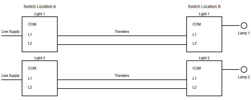
Double 2-Way Light Switch: Schematic Diagram
Step 1: Preparing the First Switch Box
Begin by installing the first switch box securely into the wall. Run the twin and earth cable from the consumer unit or power source into this box.
Connect the earth wire to the earth terminal in the back box and to the switch’s earth terminal if present. Earth continuity is essential for safety.
The following step is to take the incoming live wire, which is brown in color, from the power supply.
Then connect it to the COM terminal of the first switch. This wire provides the permanent live needed for the 2-way circuit to function.
If you are working with a double switch, repeat this process for the second COM terminal using the appropriate live feed.
Step 2: Connecting the Traveler Wires
Now run a three-core and earth cable between the first and second switch boxes. The communication between switches between each other is done by this process.
Upon reaching the first switch,
- Sleeve the black and grey wires with brown tape to show they are live.
- Connect the black wire to L1.
- Connect the grey wire to L2.
- Connect the earth wire to the earth terminal.
These traveler wires will carry the live connection back and forth depending on the position of the switches.
Step 3: Preparing the Second Switch Box
At the second switch box, connect the traveler wires exactly as they were connected at the first switch:
- L1 to L1
- L2 to L2
Next, run a twin and earth cable from the second switch box to the light fitting. The brown wire in this cable will be switched live.
Connect this brown wire to the COM terminal of the second switch. When the circuit is closed, this process allows the switch to send power to the light.
The earth wire must be connected to the switch terminal and the back box. Please recheck all connections to ensure everything is properly joined.
Step 4: Light Fixture Wiring Steps
At the ceiling rose or light fitting, connect the switched live coming from the second switch to the live terminal. As mentioned above, this live terminal is marked L.
The neutral (blue) wire from the power supply connects directly to the neutral terminal N of the light.
This connection is often made at the ceiling rose loop terminals rather than at the switch. All earth wires should be connected and bonded to the light fitting if it has a metal body.
A wiring diagram is very useful in this case. It helps to visualize how the neutral bypasses the switches. This diagram must be clear and simple to understand.
Step 5: Final Review and Testing
Before restoring power, take time to review all connections. Ensure each terminal screw is firmly tightened, and no exposed copper remains because poor connections may cause faults, overheating, or flickering.
After checking, carefully refit the switches into the boxes and fasten the faceplates. Do not force them, as trapped wires can become damaged. Please restore power at the consumer unit and test the system.
Each light should turn on and off from both switch locations. Verify all switch combinations to ensure proper operation.
Troubleshooting
Do not panic if things do not work properly and as expected. Proceed to turn the power off and verify the following points:
- Verify the live feed and switch live connections if the light does not want to turn on at all.
- Check the traveler wires on L1 and L2 if the light works from only one switch.
- The power must be turned off if flickering or sparks are seen. This may happen due to a loose or incorrect connection.
Conclusion
This guide details the standard wiring method. It used modern cable colors and commonly accepted practices.
From the above explanation, we were able to see that wiring a double 2-way light switch may look complicated.
Instead, it is simply two identical 2-way circuits housed in one unit. Understanding the role of each wire makes the task manageable. Furthermore, it is crucial to approach the task methodically.
Use a second set of traveler wires for the second switch within the double unit. This makes a second light fitting.
It should always be remembered that safety and compliance come first. A double 2-way switch provides convenience when done correctly. It also provides flexibility and a professional finish for your lighting system.
Frequently Asked Questions
What is a double 2-way light switch?
It is two separate 2-way switches in one unit, allowing two lights to be controlled from two locations each.
How many lights can it control?
It controls two independent lights or lighting circuits.
What terminals does it have?
Each switch has three terminals: COM, L1, and L2.
What cable is normally used?
Twin and earth cables are typically used for supply and light connections, while three-core and earth cables are used between switches.
Do both switches work the same way?
Yes. Each switch operates independently but follows the same wiring method.
Is a neutral wire connected to the switch?
Usually no. The neutral typically stays at the ceiling rose in UK wiring.
What are traveler wires?
They are the two wires connecting L1 and L2 between the two switches.
Why are sleeve black or grey wires brown?
This is done to indicate that the wires are live, not neutral.
What if the light works from only one switch?
The traveler wires are likely connected incorrectly.
Is it safe to do this yourself?
Only if the power is isolated and the wiring rules are followed. Otherwise, use a qualified electrician.
