4-20 mA transmitters are common in industrial automation and control; they are easy to install and easy to wire, the issue is that when they fail, most engineers struggle to troubleshoot them.
In this post i will share how to troubleshoot a 4-20 mA transmitter using just a multimeter.
What can cause a malfunctioning transmitter?
There are many things that can cause your transmitter to malfunction. The first thing to do is determine where the problem is. Problems can be caused by power, wiring, or loop device issues.
Instruments you need to troubleshoot a 4-20 mA transmitter
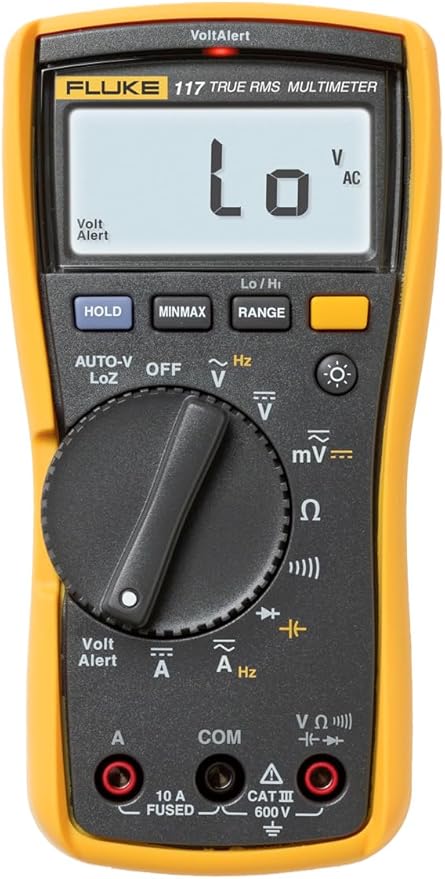
To troubleshoot a 4-20 mA loop electrically, you need a multimeter. The Multimeter should be able to read Volts and milliAmps DC.
You can find a multimeter in the hardware stores, auto parts stores, and department stores or buy it online.

How to troubleshoot A 4-20 mA Transmitter
During troubleshooting i like to divide the transmitter into three sections: the output signal (this is the 4-20 mA signal), the transmitter itself and the power source or the input.
The 4-20 ma loop
If your controller does not get the signal, please disconnect the transmitter from the controller and use a multimeter to measure the 4-20 mA.
When there is nothing on the sensor, the output should be 4 mA, and when the transmitter is at half range, the output should be 12 mA, and at full range, it should be 20 mA.
If the loop does not appear to function in any manner, then you can go and check the power and wiring.
If it appears that the loop is functioning in some manner, then the nature of the malfunction becomes important.
If the only malfunction is that the display in the controller is reading the wrong numbers, then you should first investigate setting up the display.
Please refer to the controller manual or the setting-up document in this series. Otherwise, start with the loop device section.
How to measure a 4-20 mA loop signal
Power
If the output you are getting is less than 4 mA, it is either the power supply or the wiring.
The first step in troubleshooting any circuit is to check the power supplies. Measure the loop power supply voltage, and ensure that it is at the proper level.
1) If the supply output is zero, determine if the supply is being powered, if a fuse is blown, or if the supply is damaged.
2) If the supply voltage is a little low, check to see if the supply is unregulated. Variation of the output voltage with load is normal for an unregulated supply.
3) If the supply is regulated and the output is low, it may be caused by a high loop load. Disconnect the loop and measure the voltage output.
If the source is bad or there is a faulty fuse, you will need to fix it or replace it depending on what applies to you.
Wiring
Check the wiring. The power supply + terminal should be run to the + terminal of the first item in the loop.
The – terminal of the first item on the loop should be run to the + terminal of the second item on the loop, and so on until the wiring returns to the – terminal of the power supply.
With the loop supply powered, measure the voltages across the devices in the loop.
The voltages on the loop devices should agree with the specifications for those devices, and the voltage polarity must agree with the + and – of the terminal block.
If the voltages across all the loop devices are zero, and the loop supply is within specification, then there is a break in the loop.
If most, if not all, of the voltage occurs across any one of the loop devices, then there is a problem with that device.
The transmitter
Troubleshooting a transmitter depends on the type of the transmitter. The most important troubleshooting step is to make sure that it is wired properly.
Most transmitters I have ever worked with have displays; if this is the case, usually they will show you an error code or warning, you can check that code on the transmitter user guide, and you can get an idea of what you are dealing with.
Another thing you can check here is the LED lights, in most transmitters, RED means alarm, yellow means the transmitter is at fault, and Green means it is working, this is not in all of them; you need to verify in the user guide for the specific transmitter.
Key takeaways
Most issues with the transmitter are due to wrong wiring; please make sure that they are wired properly. Transmitters can be damaged by attaching power to the wrong terminals.
If the device is wired properly, measure the voltage across the transmitter to check the polarity and to make sure that it has sufficient voltage to operate by comparing the measured voltage to the minimum in the specifications for that transmitter.
Sensors must be properly attached; check the wiring diagram for the transmitter to ensure that it is proper.
If you do all of that and the transmitter still is at fault, you need to contact the manufacturer for further troubleshooting and possible return of the transmitter to the manufacturer.