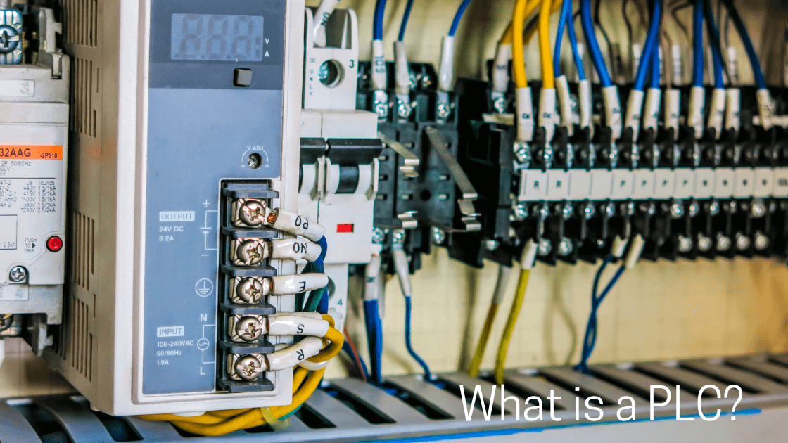
A PLC, which stands for Programmable Logic Controller, is an industrial computer that acts as the “brain” that processes input to obtain the desired/controlled output, such as induction motor speed and industrial robot arm position, among others.
The PLC works similarly to any computer, but it is just designed to work in an industrial environment.
So, it can survive in tough conditions such as excessive heat, dust, vibration, and electrical noise.
In this article I share a brief history of a PLC, how a PLC is composed, how many types of PLCs there are, how many languages PLCs speak, and finally, the ways to connect a PLC to the load in a correct manner.
The Journey of a PLC
Relay logic is a method of electrical control that uses electromechanical relays to perform logical operations and control circuits.
Before PLCs, industrial automation relied on relay logic systems, large panels full of relays, timers, and wiring.
These were bulky, hard to troubleshoot, and expensive to modify whenever a production line changed.
This was back then in the 1960s; the technology changed, and today we have the PLCs that we are talking about in this article. So, in 1968 the engineers came up with the idea of substituting these bulky relays.
The Main Parts of a PLC
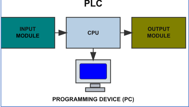
A PLC generally contains four main sections: A power supply, an input part, a Processor (CPU/brain) part, and an output part.
Power Supply
The power supply is the one that gives energy to the CPU. It has a DC-DC converter that takes the normal line voltage to 24VDC to provide DC power to the rest of the connected devices.
Input Section
This is where the PLC receives signals from the outside world, just like your desktop PC when you click a mouse or when you type something using your keyboard (mouse and keyboard are the inputs).
But when it comes to a PLC input can be sensors, switches, buttons, or any device that sends information (for example, a temperature sensor or a start button).
Processor (CPU/Brain)
As aforementioned, the CPU is the brain of the PLC. It reads the inputs, processes them according to the program written by the user, and decides/controls what the outputs should do.
Programming Device
Usually it’s a normal PC; after programming using special software, the instructions are loaded to the PLC CPU memory. Then the PLC will be ready to execute these instructions to get the desired output signal.
Output Section
Devices such as motors, lamps, valves, or relays are located at the output section of a PLC.
They are also known by the name of actuators. The CPU tells them when to turn ON or OFF or when to act.
Note that the devices connected to the input section, as well as those that are connected to the output section, are in general called the field devices.
Types of PLC
PLCs are mainly categorized into two types based on their hardware design: Compact (or Fixed) PLCs and Modular PLCs.
Although as the technology keeps growing, other classifications have emerged such as Nano/Micro/Mini PLC, safety PLCs and Soft PLCs.
Compact (Fixed) PLC
- All components (CPU, power supply, and I/O modules) are housed in a single unit.
- Pros: Simple and low cost.
- Cons: Limited expansion options.
- Use: Small, dedicated automation tasks.
Modular PLC
- Components are separate: CPU, I/O modules, and power supply are installed in racks.
- Pros: Scalable and flexible.
- Cons: More expensive and larger.
- Use: Medium- to large-scale automation.
Other Classifications
- Nano/Micro/Mini PLCs: These are small in size and have low processing power of the PLC, typically used in very small-scale operations.
- Safety PLCs: Designed with enhanced safety features to control hazardous processes and protect personnel.
- Soft PLCs: A general-purpose computer that runs PLC software and functions as a PLC, rather than using a dedicated hardware controller.
Sinking and Sourcing in PLCs
In PLCs, the terms “sinking” and “sourcing” are very important when it comes to physical connection of the PLCs with the input/output (I/O) devices.
They describe how current flows between the PLC I/O terminals and the field devices (sensors, switches, actuators).
So, during sourcing, current goes from the PLC to the field device, and during sinking, current flows from the field device to the PLC.
Please refer to the diagram shown below for more understanding of these important terminologies.
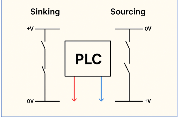
The difference between sink and source
Introduction to PLC Programming Languages
For the PLC brain (CPU) to do its job, it needs to be programmed with some instructions (Programming language). A PLC brain understands/talks the following languages.
Ladder Diagram (LD)
This is a graphical language equivalent to traditional electrical relay logic diagrams. It uses contacts as inputs, such as switches, sensors, and coils, and outputs, such as motors and lamps, to represent logical operations.
Function Block Diagram (FBD)
This is also a graphical language that uses predefined function blocks to represent logical functions.
The blocks can be fully functioning components such as timers, counters, and PID controllers, among other components.
Structured Text (ST)
This language has the ability to use the standard low-level programming instructions like IF-THEN-ELSE, FOR loops, and WHILE loops.
Instruction List (IL)
This also has low-level capability, but it’s a text-based, assembly-like language that uses instructions like LD for load and AND for logical AND.
Sequential Function Chart (SFC)
A graphical language used to organize and structure a PLC program into a sequence of steps, transitions, and actions.
Main PLC Brands
There are brands like Delta and Noark that are good choices if you have a small project.
But the main brands of PLCs include Siemens, Rockwell Automation (Allen-Bradley), Schneider Electric, Mitsubishi Electric, Omron, and ABB.
These companies are known for offering innovative, reliable, and extensive ranges of products for industrial automation, though specific brand choice depends on application needs, budget, and industry focus.
Key Takeaways: What is the PLC?
This article addressed a brief history of a PLC, how a PLC is composed, and types of PLCs.
Furthermore, it discussed how many languages PLCs speak and finally the ways to connect a PLC to the load in a correct manner.
As a result, it can be proved that PLC is indeed the brain of industrial automation. Furthermore, understanding concepts like sinking and sourcing also helps to ensure proper and safe connections between the PLC and field devices, as well as the field personnel/operator.
If you’re just starting out, remember: learning PLCs is a step-by-step journey, but mastering them opens the door to countless opportunities in automation and control.
Want to keep learning more about the PLCs? Please do not hesitate to read our next article for more beginner-friendly guides.
FAQ: What is a PLC?
What is a PLC and how does it work?
A PLC, which stands for Programmable Logic Controller, is an industrial computer that acts as the “brain” that processes input to obtain the desired/controlled output, such as induction motor speed and industrial robot arm position, among others.
Why were PLCs invented?
Initially, industrial automation relied on banks of hard-wired relays—complex, bulky, and difficult to modify.
PLCs were developed to replace these systems, offering flexibility through programmable logic.
Who invented the first PLC?
The first PLC (Modicon-084) was created by Richard Morley in 1968, and his team at Bedford Associates. It was specifically made for General Motors.
What are the main components of a PLC?
A PLC generally contains four main sections: an input part, a Processor (CPU/brain) part, and the output part.It may also contain a power source, or you can just add it yourself.
What programming languages are used in PLCs?
PLCs are programmed using IEC 61131-3 standard languages, including:Ladder Diagram (LD): which is a graphical format resembling a relay circuit. Function Block Diagram (FBD): uses reusable logic blocks.
Structured Text (ST): textual, high-level logic with IF/THEN/LOOP structures. Instruction List (IL): low-level, assembly-like text. Sequential Function Chart (SFC): flowchart-like steps and transitions.
Where can I use a PLC?
PLCs are mostly used in industries and control systems, including: Manufacturing lines, automotive assembly, packaging, and industrial robotics. Also, in building systems like elevators, traffic lights, and automatic doors.
How do I choose the right PLC?
This depends on your application requirements, such as the required number of inputs/outputs, Types of inputs/outputs (the latter could be either digital or analog), and the processing capability of a CPU, among other factors.
What are the steps to learn PLC programming?
Start with beginner-friendly projects like switching the diode ON and OFF then proceed with traffic lights or sump pumps.
Using vendor learning platforms such as Siemens S7-1200 or Rockwell CompactLogix is often recommended for ease of programming.
How does a PLC read sensors?
A PLC reads sensors through its input modules. The sensors send signals to the input modules, which convert them into digital data for the CPU (brain) to manipulate them before sending them to the output modules.
Which of the PLC programming languages is easier to learn for PLC?
Ladder Diagram (LD) is generally considered the easiest programming language to learn for PLCs, especially for beginners with a background in electrical circuits or relay logic.
So, it is a graphical language equivalent to traditional electrical relay logic diagrams.
