A Programmable Logic Controller (PLC) is a specialized digital industrial computer. It has been designed and ruggedized to reliably handle automation and control tasks in industrial environments where dust, vibration, heat, and electrical noise are present.
It constantly monitors the state of connected input devices, makes logical decisions using a custom user-defined program, then updates the state of output devices.
This article introduces the fundamental steps for programming a PLC using Totally Integrated Automation Portal (TIA Portal) software from Siemens. It explains the importance of TIA Portal as a development tool.
Then, it describes how to configure the software, and shows step-by-step instructions to create a program using ladder logic (LD).
Finally, it walks through the process of downloading the program into a real PLC and verifying its operation.
The Siemens TIA Portal
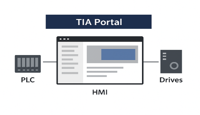
The TIA Portal is Siemens’ flagship engineering framework. It is an all-in-one software suite that provides a single, unified platform for programming, configuring, and commissioning automation systems.
Instead of using multiple separate tools, TIA Portal integrates all essential automation engineering functions into one environment, making it easier for engineers to work efficiently.
Within TIA Portal, different engineering tools coexist in harmony. For PLCs, it uses STEP 7, which is the programming environment. For operator interfaces such as Human-Machine Interfaces (HMIs), it uses WinCC.
For drive systems and motion control, it integrates Startdrive. This tight integration means that an engineer can configure hardware, program logic, and design operator panels in a consistent workflow.
Why choose TIA Portal?
TIA Portal is widely chosen because it significantly streamlines the entire engineering process.
It allows engineers to reduce development time, eliminate redundancies, and increase consistency across projects.
The intuitive user interface, powerful libraries, and drag-and-drop features help make programming accessible, even to beginners.
Another advantage is its flexibility in supporting multiple international programming languages defined by IEC 61131-3. These include:
- Ladder Logic (LAD) – graphical, easy to understand, resembles electrical circuits.
- Function Block Diagram (FBD) – suited for process control and data flow.
- Structured Control Language (SCL) – text-based, similar to high-level programming languages.
This versatility makes TIA Portal a preferred choice for both newcomers and experienced engineers working on complex industrial automation projects.
The Best PLC Simulation Software in 2025
How to Write Your First PLC Program in Siemens TIA Portal
Step 1: Planning your first program
Define your application
Before any code is written, the very first step in PLC programming is planning. A well-structured plan ensures that the logic is clear, the requirements are met, and unnecessary mistakes are avoided.
Clearly define what you want the program to achieve. For beginners, it is best to start with a simple application that illustrates basic control principles.
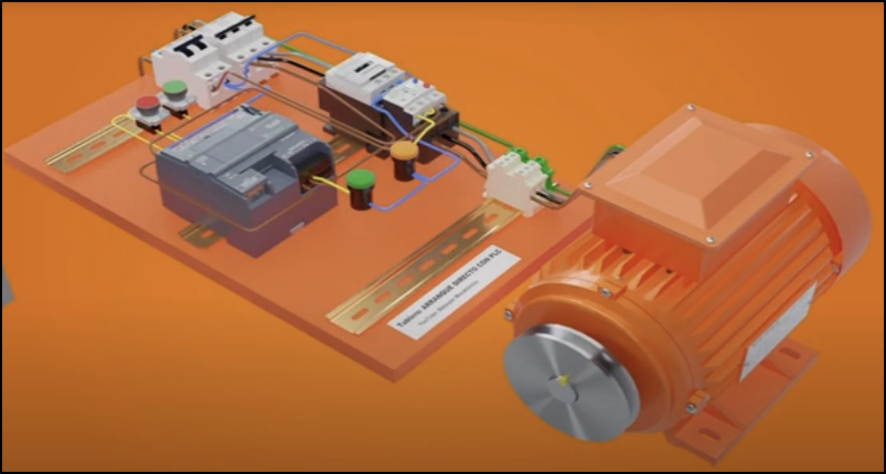
Example application: A motor start/stop circuit using pushbuttons and an indicator lamp.
Requirements:
- A start pushbutton should turn the motor ON.
- A stop pushbutton should turn the motor OFF.
- The motor should remain running (latched) even after the start pushbutton is released.
- A status light should indicate when the motor is running.
This simple yet practical example teaches the concept of latching circuits, which is fundamental in PLC programming.
Define your inputs and outputs (I/O)
Every PLC program is connected to real-world devices. These devices are classified as inputs (information coming into the PLC) and outputs (commands sent from the PLC).
To avoid confusion, each device must be clearly listed, assigned a descriptive tag name, and mapped to a data type.
| Device | Type | Data Type | Description |
| Start_PB | Input | BOOL | Activated when the start pushbutton is pressed |
| Stop_PB | Input | BOOL | Activated when the stop pushbutton is pressed |
| Motor_Running | Output | BOOL | Controls the motor starter coil |
| Motor_Light_ON | Output | BOOL | Turns on the lamp when the motor is running |
Step 2: Creating a new project
Launch TIA Portal
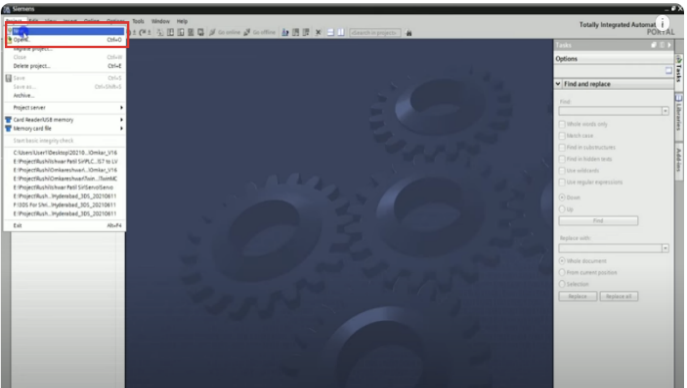
Open TIA Portal software from your desktop or start menu. Once the program loads, you will see the start screen with several options.
Create a new project
- On the start screen, click “Create new project”.
- Enter a project name, such as My_First_PLC_Program.
- Choose a file path to save the project.
- Click “Create” to confirm.
Configure a device
- On the “First steps” page, click “Configure a device”.
- Select “Add new device”.
- Expand the Controllers folder.
- Choose from the SIMATIC S7-1200 or S7-1500 series. (The S7-1200 is highly recommended for beginners due to its affordability and flexibility.)
- Select the exact CPU model that matches your hardware.
- Click “Add” to include it in the project.
Step 3: Hardware configuration
Assigning IP address
- Once the CPU is added, the device view opens.
- In the properties window at the bottom, select “PROFINET interface”.
- Under Ethernet addresses, enter an IP address for the PLC, e.g., 192.168.0.1.
- This address will be used later to connect the PC with the PLC.
Configuring I/O addresses
- In the same properties, go to “I/O addresses”.
- These addresses are where the PLC program links to actual hardware inputs and outputs.
- By default, for an S7-1200, inputs often start at %I0.0 and outputs at %Q0.0.
- Verify or adjust these addresses to match your application.
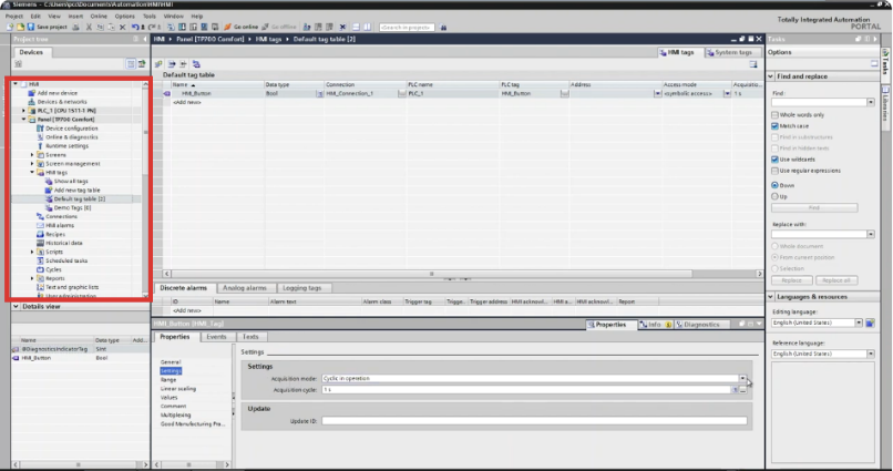
Step 4: Creating PLC tags
Open the default tag table
- In the project tree, expand “PLC tags”.
- Double-click “Default tag table”.
- A table opens where you can create tags for your I/O devices.
Add your tags
- Add a new tag for each I/O defined in the plan.
- Assign tag names and data types (all BOOL in this example).
- The software automatically assigns addresses, but they can be changed.
| Tag Name | Data Type | Address |
| Start_PB | BOOL | %I0.0 |
| Stop_PB | BOOL | %I0.1 |
| Motor_Running | BOOL | %Q0.0 |
| Motor_Light_ON | BOOL | %Q0.1 |
Step 5: Writing the Ladder Logic program
Open the Main Program Block (OB1)
- Expand “Program blocks” in the project tree.
- Double-click “Main [OB1]”.
- This block runs cyclically and forms the backbone of the program.
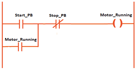
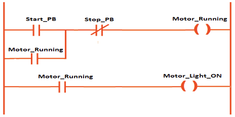
Program Network 1: Start/Stop logic
This network contains the motor latching circuit.
- From the Basic Instructions panel, drag a Normally Open Contact (NO).
- Place another NO contact in parallel with it.
- Add a Normally Closed Contact (NC) in series.
- Place a Coil (=) at the end.
Wiring:
- Assign Start_PB to the first NO contact.
- Assign Motor_Running to the parallel NO contact.
- Assign Stop_PB to the NC contact.
- Assign Motor_Running to the coil.
Logic: If Start_PB is pressed OR Motor_Running is already latched, AND Stop_PB is not pressed, then Motor_Running stays ON.
Program Network 2: Status light
This network turns on the lamp when the motor is running.
- Insert an NO contact.
- Insert a Coil.
- Assign Motor_Running to the contact.
- Assign Motor_Light_ON to the coil.
Logic: If Motor_Running = TRUE, then Motor_Light_ON = TRUE.
Step 6: Simulating the program
Start the simulation
- Save the project.
- Select the PLC in the project tree.
- Click “Start simulation”.
- Confirm the pop-up window.
- The program compiles and loads into the virtual PLC.
- Select “Start all” to begin simulation.
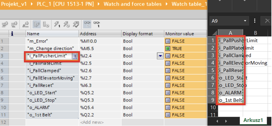
Test with a watch table
- Expand “PLC tags” → “Show all tags”.
- Open the watch table.
- Modify the Start_PB tag to True. Observe Motor_Running and Motor_Light_ON.
- Return Start_PB to False – the motor should remain latched.
- Change Stop_PB to True – the motor and lamp should turn off.
Step 7: Downloading to a physical PLC
Establish communication
- Connect PC to PLC via Ethernet.
- In TIA Portal, click “Go online”.
- Select your network adapter.
- Search for accessible devices.
- Assign an IP if required.
Download the program
- Right-click CPU → “Download to device”.
- Select hardware + software.
- Confirm settings → Load.
- After download, choose “Start all modules”.
- The PLC enters RUN mode.
Monitor and debug
- Open OB1.
- Enable Monitoring on/off.
- Observe green power flow lines.
- Use pushbuttons to test and verify outputs.
Key Takeaways: How to Write Your First PLC Program in Siemens TIA Portal
You have successfully gone through the process of planning, programming, simulating, and downloading a PLC program using Siemens TIA Portal.
This motor start/stop application demonstrates a core concept: latching circuits, which are the foundation of industrial automation.
By mastering this workflow, you now have a solid base to explore more advanced topics such as timers, counters, data blocks, and structured programming. Always remember to:
- Plan your project carefully before coding.
- Use descriptive tag names for clarity.
- Simulate and test your program thoroughly before deploying.
With experience, you will be able to create structured, scalable PLC applications that control entire production systems.
FAQ: How to Write Your First PLC Program in Siemens TIA Portal
What is TIA Portal used for?
TIA Portal is Siemens’ engineering software used to program PLCs, configure HMIs, commission drives, and manage industrial networks within one integrated environment.
Which PLCs can be programmed with TIA Portal?
TIA Portal mainly supports Siemens PLCs such as the S7-1200, S7-1500, S7-300, and S7-400, along with related devices.
Is ladder logic the only programming language available?
No. TIA Portal supports LAD, FBD, SCL, and also function charts, giving engineers flexibility in programming style.
Do I need real hardware to practice?
Not necessarily. TIA Portal includes PLCSIM, a simulation tool that allows you to test logic without a physical PLC.
How do I connect my PLC to TIA Portal?
You typically connect via Ethernet, assign an IP address, and then use the “Go online” function to establish communication.
Can I program safety PLCs with TIA Portal?
Yes, Siemens offers Fail-Safe CPUs that can be programmed in TIA Portal with additional safety libraries.
