A Human-Machine Interface (HMI) talks to a Programmable Logic Controller (PLC). The HMI is the control screen that operators use to monitor and interact with processes.
The PLC, on the other hand, is the brain of the machine, executing control logic and handling inputs and outputs from sensors and actuators.
Connecting them lets you see real-time machine information, adjust setpoints, and control operations safely and efficiently.
This article plays as a practical guide that explains how to connect an HMI to a PLC. It will cover the basic steps, which includes hardware selection, software setup, network configuration, and testing.
The purpose is to give beginners, students, and even working engineers a simple but complete roadmap to follow when integrating these two important components of automation systems.
How to Connect HMI to PLC? Step by Step
When you connect an HMI to a PLC, you essentially build a communication bridge. Think of it like connecting a computer monitor and keyboard to a CPU; the monitor displays what the CPU is doing, while the keyboard provides commands.
In the same way, the HMI displays PLC data (like motor status, temperature, or tank level) and lets the operator press virtual buttons to send commands back to the PLC.
Step 1: Choose Your Hardware and Software
Know Your Devices
Look carefully at your HMI and PLC hardware. Check the model numbers, manuals, and technical specifications.
For instance, a Siemens HMI might communicate differently from an Allen-Bradley HMI.
You need to know exactly what they are, because this helps with compatibility and avoids hours of wasted troubleshooting later.
Manufacturers often provide compatibility charts that show which HMI models support which PLC models.
Check for Compatible Protocols
HMIs and PLCs must speak the same language. This language is called a communication protocol. Common industrial protocols include Ethernet/IP, Modbus, and PROFINET.
For example, if your PLC supports Modbus TCP but your HMI only supports EtherNet/IP, they cannot communicate directly.
Your devices must support the same protocol, or you may need a communication gateway.
Always plan this early, since protocol mismatches are one of the most common reasons for failed setups.
Gather Your Software
You will need two different software programs. One is the PLC programming software (such as TIA Portal for Siemens or RSLogix for Allen-Bradley).
The other is the HMI design software (like WinCC, FactoryTalk View, or Weintek EasyBuilder).
The HMI software is used for designing the screens, buttons, and graphics that operators will interact with.
The PLC software is for programming the machine logic, such as starting motors, reading sensors, and handling alarms.
Get the Right Cable
The type of cable depends on the chosen protocol. For Ethernet, you use a standard Ethernet cable, usually CAT5e or CAT6.
For serial communication (like Modbus RTU), you might use an RS-485 cable, which has differential signaling for long distances.
Make sure the cable is in good condition, properly shielded, and suitable for industrial environments to avoid communication errors caused by electrical noise.
Step 2: Connect the Hardware
Physical Connection
Connect the HMI and PLC with the chosen cable. Each device has specific ports:
Ethernet ports look like computer LAN connectors, while RS-485 ports often use terminal blocks with labeled A+ and B- terminals.
Match the wiring carefully. For Ethernet, simply plug into the Ethernet port. For RS-485, double-check polarity because reversing wires will prevent communication.
Using a Network Switch
If you have more than one PLC or if your HMI must also connect to a SCADA system, you may need a network switch.
The switch connects all devices together in a star topology. This allows multiple devices, including engineering laptops, to share the same network.
For a simple setup, however, you can connect the HMI directly to the PLC with one cable.
Power On
Once the wiring is complete, power on both the HMI and the PLC. Confirm that they boot properly.
The power indicator lights should be lit and steady. If a device fails to power up, check your power supply rating, fuse protection, and wiring polarity. Stable power is crucial for avoiding intermittent disconnections.
Step 3: Configure the PLC Software
Create a Project
Open the PLC programming software and create a new project. This defines the workspace where you will add hardware and logic.
Add Your PLC
Select and add your specific PLC model from the software’s hardware catalog. This ensures the correct settings and memory layout are applied.
Set Up Communication
Go to the communication or network settings. Define the communication protocol that matches your HMI.
For Ethernet, assign an IP address and subnet mask. Ensure that the IP address is unique and does not conflict with other devices in the network.
For serial communication, configure the baud rate, data bits, parity, and stop bits exactly as required.
Enable Communication Access
Some PLCs require enabling communication services. For example, Siemens PLCs may require enabling PUT/GET communication under protection settings. Without this, the HMI might be blocked from reading or writing data.
Define Tags
Tags are symbolic names for memory addresses inside the PLC. Defining clear and descriptive tags is essential for linking with the HMI.
For instance, instead of using “MW100,” define a tag called “TankLevel” to represent a water tank level sensor. This makes programming and troubleshooting much easier.
Write Your PLC Program
Develop the control logic using ladder logic, function blocks, or structured text. This is where you define machine operations, such as starting pumps, monitoring pressure, or shutting down equipment during emergencies.
Download to PLC
Transfer both the logic program and the communication configuration to the PLC. Test the program locally to ensure that inputs and outputs respond correctly.
Step 4: Configure the HMI Software
Create a New Project
Open the HMI design software and start a new project.
Select HMI Model
Choose the exact model of your HMI device from the list. This ensures that the right screen resolution, memory size, and supported drivers are loaded.
Configure Communication
Open the communication settings and select the same protocol as the PLC. If using Ethernet, enter the PLC’s IP address.
If using serial, input the same baud rate and parity settings. This creates the communication link between the two devices.
Set HMI IP Address
For Ethernet setups, assign a unique IP address to the HMI. Make sure it belongs to the same subnet as the PLC.
For example, if the PLC is 192.168.1.10, you might assign the HMI 192.168.1.20.
Map Tags
Create HMI tags and link them to PLC tags. For example, the HMI tag “TankLevelDisplay” might link to the PLC tag “TankLevel.” This mapping allows the HMI to read real-time values and write commands back.
Design the Screens
Use the HMI software’s graphical tools to create the operator interface. Add buttons, lamps, meters, and trend charts.
For example, a “Start Motor” button might link to a PLC coil, while a red alarm light might indicate an over-temperature condition.
Download to HMI
Finally, download the HMI project to the physical HMI device. This usually requires connecting via USB, Ethernet, or serial cable depending on the model.
Step 5: Test the Connection
Initial Test
Once everything is configured, check the HMI screen. It should display live data from the PLC.
For example, if you linked the “TankLevel” tag, filling the tank should update the HMI display automatically.
Test Commands
Try sending a command from the HMI. For example, press the “Start Pump” button. The PLC should receive the command, and the pump output should energize.
Check for Errors
Both PLC and HMI software usually provide diagnostic tools. Use them to check for error messages or failed connections.
Troubleshoot Problems
If communication does not work, check step by step:
- Check the cable: Is it firmly connected? Is it damaged?
- Check the power: Are both devices properly powered?
- Check settings: Do the IP addresses or baud rates match?
- Check firewall: Is your PC or network firewall blocking communication?
- Check wiring: For serial connections, verify that A+ and B- wires are not swapped.
Common Connection Types
Ethernet/IP
A popular protocol, especially with Allen-Bradley PLCs. It is fast, reliable, and widely supported. Requires Ethernet cables and IP address configuration.
Modbus TCP/IP
Another common Ethernet-based protocol, supported by many brands. Simple to set up, making it a great starting point for beginners.
Modbus RTU
A serial communication protocol used over RS-485 cables. Ideal for low-speed, long-distance communication. Requires careful setting of baud rate, parity, and stop bits.
PROFINET
A protocol widely used in Siemens environments. Very fast and precise, suitable for synchronized automation tasks. Uses standard Ethernet cables but requires proper network planning.
Advanced Considerations
Security
Modern industrial networks face cybersecurity risks. Consider using secure protocols like OPC-UA or enabling password protection on both PLC and HMI.
Multiple PLCs
A single HMI can be configured to communicate with multiple PLCs. This is common in larger plants. Each connection must be configured separately, and tags should be organized clearly.
Documentation
Always document your work. Write down all communication settings, IP addresses, and tag names. This helps during troubleshooting, maintenance, and future upgrades.
Best Practices
- Use high-quality, shielded cables to reduce noise.
- Avoid routing communication cables next to high-voltage power lines.
- Keep both HMI and PLC firmware updated to prevent bugs.
- Label network cables for easier maintenance.
- Always test your setup in a safe environment before deploying in production.
Key Takeaways: How to Connect HMI to PLC
This article served as a step-by-step guide and explained how to connect HMI to PLC.
It covered the basic steps, which included hardware selection, cable connections, software configuration, and testing.
From the discussion above, it is clear that connecting an HMI to a PLC is a key task in automation that bridges human control with machine intelligence. It requires careful planning and execution.
You must choose compatible hardware and protocols, connect the devices physically, configure both PLC and HMI software, and define data tags.
Finally, you must test the connection thoroughly and troubleshoot any issues systematically.
By following these simple steps and best practices, you can successfully connect your HMI to your PLC, ensuring smooth, safe, and efficient operation in industrial environments.
FAQ: How to Connect HMI to PLC
What are the essential steps to setup HMI-PLC communication?
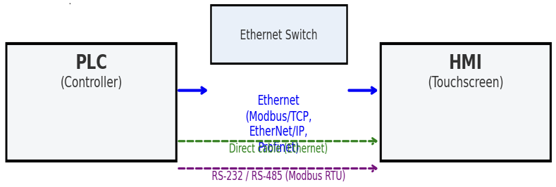
The general workflow involves: Physical Connection (Ethernet, RS-485, RS-232); Protocol Compatibility (Modbus RTU/TCP, EtherNet/IP, PROFINET, OPC UA); Configuration- assign IP addresses or serial settings.
Can an HMI interface with multiple PLCs or vice versa?
Yes, it’s commonly supported. You simply add a separate communication connection (and corresponding tag mapping) for each PLC in the HMI software. Likewise, a PLC could be accessed by multiple HMIs.
What if the physical connections or protocols don’t match?
Use a serial converter (RS-232 to RS-485) or a gateway/protocol converter to bridge incompatible interfaces or protocols.
These solutions are especially handy when integrating older PLCs with modern HMIs or vice versa.
Can wireless connections be used instead of wired ones?
Yes, if both devices support wireless modules (Wi-Fi or cellular), you can establish a wireless link.
However, note that wireless setups require extra attention to security and potential interference issues.
Why isn’t my HMI communicating correctly with the PLC even though IP addresses match?
Several factors might cause this:
- Some HMIs require a network switch rather than a direct cable connection
- Ensure communication settings are correctly defined in the HMI (e.g., correct protocol, station IDs, etc.).
- Use ping tests or diagnostic tools to confirm connectivity. Users on forums often troubleshoot with tools like ping and network diagnostics
Do HMIs need to be added to the PLC’s I/O tree?
No. Usually, HMIs operate as a client, requesting data from the PLC rather than being part of its I/O configuration.
As long as both devices are on the same network/protocol, the communication works
