In modern industrial automation, precise monitoring and control depend on the smooth communication between field devices and controllers.
One of the most important examples is the integration of a pressure transmitter with a Programmable Logic Controller (PLC).
A pressure transmitter converts a physical pressure value into a standard electrical signal, usually 4–20 mA, that the PLC can interpret.
The PLC then uses this signal to make decisions, such as opening a valve, activating a pump, or triggering an alarm.
This interaction forms the foundation of automated systems in industries like manufacturing, chemical processing, oil and gas, and water treatment. The result is better efficiency, improved safety, and greater reliability.
This article details how a pressure transmitter works with a PLC, explaining the signal conversion process and integration steps.
It also introduces best practices, and common troubleshooting methods used in industrial automation.
Pressure Signal to PLC Program
The path from a process’s actual pressure to PLC decision making involves three main stages: Pressure sensing at the source, signal conversion and transmission and PLC processing and control
In the following subsections we will take a look at each step, in detail.
Pressure Sensing at the Source
The first task of a pressure transmitter is to sense the actual pressure of a fluid either gas or liquid.
Inside the transmitter, a sensing element (often a diaphragm) deflects slightly in response to changes in pressure.
This mechanical deflection is the basis for the measurement. Different transmitters measure different pressure types:
- Gauge Pressure: Compares pressure to the surrounding atmosphere.
- Absolute Pressure: Compares pressure to a perfect vacuum.
- Differential Pressure: Measures the difference between two separate pressure points, such as across a filter or tank.
Converting Pressure to Electrical Signal
Once the pressure is sensed, the transmitter’s internal electronics convert it into a standardized electrical signal.
The most widely used output is the 4–20 mA current loop. It’s preferred because current signals resist electrical noise and remain stable over long cable distances.
How the 4–20 mA Loop Works:
- The transmitter typically operates as a 2-wire device.
- The same two wires provide both power and signal.
- The PLC supplies 24 V DC to power the transmitter.
- The transmitter modulates the current between 4 mA (minimum) and 20 mA (maximum) to represent the measured pressure.
- 4 mA = 0% of the pressure range
- 20 mA = 100% of the pressure range
- 12 mA = approximately 50% of the range
- This current signal travels to the PLC’s analog input module, which measures it.
PLC Processing and Control
The PLC’s analog input module converts the received 4–20 mA signal into a digital integer value.
This raw number must be scaled into real world engineering units like bar or psi so that the control logic can use it.
Scaling the Input
Scaling converts the raw input into readable engineering values. The general formula is:

For example: 4 mA = 0 bar; 20 mA = 10 bar; A midrange signal (12 mA) represents about 5 bar.
Once scaled, the PLC program uses this value for decision making.
Executing Control Logic
The PLC compares the scaled pressure with pre-set limits:
- If the pressure drops below a lower limit, it may start a pump.
- If it rises above a high limit, it can shut down equipment or trigger alarms.
This ensures safe, automatic operation and reduces the need for manual intervention.
Integrating the Pressure Transmitter with a PLC
Integration requires correct hardware selection, proper wiring, and accurate software configuration.
Step 1 – Selecting the Right Hardware
Choose a pressure transmitter that fits the process requirements:
- Pressure Type: Gauge, absolute, or differential
- Range: The expected operating pressure range
- Accuracy: Depending on process criticality
- Material Compatibility: Must match the process fluid
Also, ensure that the PLC’s analog input module supports the same signal type (e.g., 4–20 mA). Some modules accept voltage signals, so compatibility is important.
Step 2 – Wiring the Components
Before wiring, turn off all power sources and follow lockout/tagout safety procedures.
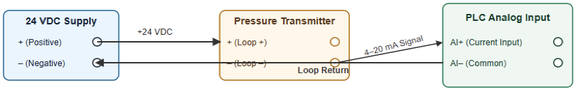
Connecting a 2-Wire Transmitter:
- Connect the positive (+) terminal of the 24 V DC power supply to the positive (+) terminal of the transmitter.
- Connect the negative (–) terminal of the transmitter to the analog input channel of the PLC.
- Connect the common terminal of the analog input module back to the negative (–) terminal of the power supply.
This completes the current loop.
Grounding: Proper grounding is essential. It prevents electrical noise and ensures accurate signal transmission.
Step 3 – Configuring the PLC
Set the Input Range:
In the PLC’s hardware configuration, define the analog input channel as 4–20 mA. This ensures the PLC interprets the signal correctly.
Apply Scaling:
Use scaling blocks or math functions in the PLC program to convert the raw digital input into engineering units.
This allows operators to see the actual pressure on the HMI (Human-Machine Interface).
Define Alarms and Logic:
Program the PLC to take specific actions when pressure limits are reached:
- Low-pressure alarm: Warns or starts a pump
- High-pressure alarm: Shuts off valves or stops pumps
- Critical limit: Activates an emergency shutdown (ESD)
These logic steps transform raw data into actionable control.
Best Practices and Troubleshooting
Even well-designed systems can experience issues. Following installation best practices helps prevent problems and improves accuracy.
Best Practices
Avoid Electrical Noise
Use shielded cables and route them away from power cables or variable frequency drives (VFDs).
Stable Mounting
Install transmitters away from vibration, heat, or direct sunlight.
Regular Calibration
Calibrate transmitters periodically to maintain accuracy. Calibration involves applying known pressures and adjusting the transmitter’s zero and span.
- zero and span.
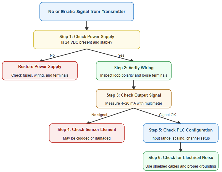
Common Problems and Solutions
| Problem | Possible Cause | Solution |
| No signal (4 mA constant) | No power, broken wire, or blocked sensor | Check power supply, wiring, and sensor diaphragm |
| Full signal (20 mA constant) | Pressure exceeds range or calibration error | Verify process pressure and recalibrate |
| Erratic reading | Electrical noise, loose wiring, or vibration | Check shielding, grounding, and mounting |
Advantages of PLC-Integrated Pressure Transmitters
Connecting pressure transmitters to PLCs brings multiple operational benefits.
Enhanced Process Control
Real-time data allows for precise and automated adjustments. Processes stay consistent and efficient, ensuring stable production quality.
Increased Safety
Continuous monitoring detects unsafe pressure levels early. PLCs can immediately shut down equipment or trigger alarms to prevent damage or accidents.
Better Data and Analytics
PLCs can log and trend pressure data. Engineers use this information to optimize performance, predict maintenance needs, and detect gradual system degradation.
Reduced Costs
Optimized operations lower energy consumption, reduce waste, and minimize downtime. Over time, these savings justify the investment in automation.
Case Study: Tank Level Monitoring Using a Differential Pressure Transmitter
To understand this integration in practice, consider a chemical plant where a PLC maintains the level in a storage tank using a differential pressure (DP) transmitter.
Measurement
The DP transmitter measures the pressure difference between the bottom and the top of the tank.
This difference corresponds directly to the liquid height, since pressure at the base depends on fluid density and height.
Signal Transmission
The transmitter converts this pressure difference into a 4–20 mA signal and sends it to the PLC’s analog input.
PLC Logic
- The PLC reads the 4–20 mA signal.
- It scales it into engineering units (for example, 0–10 meters of tank level).
- The ladder logic then executes the following:
- If the tank level falls below 20%, the PLC turns on a pump to refill.
- When the level reaches 90%, the pump turns off.
- If the level exceeds 95%, a high-level alarm activates.
Control Outcome
This automation keeps the tank level within a safe and efficient range.
It prevents overflow, reduces waste, and ensures continuous production without manual intervention.
Key Takeaways: How a Pressure Transmitter Works with PLCs
This article introduced how a pressure transmitter works with a PLC, by detailing the signal conversion process and integration steps.
In addition, it studied the best practices, and common troubleshooting methods used in industrial automation.
This leads to conclude that the pressure transmitter–PLC system is a cornerstone of industrial automation.
It transforms physical pressure into a digital signal that drives intelligent control decisions.
By following correct installation steps, configuring inputs properly, and maintaining calibration, engineers can create accurate, efficient, and safe control systems.
The ability of PLCs to interpret and act on pressure data enables smarter factories, where processes are optimized, downtime is minimized, and safety is always prioritized.
From simple tank monitoring to complex process control, the integration of pressure transmitters and PLCs continues to power the future of industrial automation.
FAQ: How a Pressure Transmitter Works with PLCs
What is the difference between a pressure transducer and a pressure transmitter?
- A pressure transducer converts pressure into a small electrical signal (e.g., voltage or resistance).
- A pressure transmitter includes signal conditioning and outputs a standardized signal (often 4–20 mA) that is easier for PLCs or other control systems to read.
Why is the 4–20 mA current loop standard used for transmitters?
- The 4–20 mA loop is resistant to electrical noise over long cable distances, making it reliable in industrial environments.
- The current loop can both power the transmitter and carry the signal (in two-wire devices).
- Because the signal is current (not voltage), voltage drops in the wires don’t alter the reading.
How is a pressure transmitter wired to a PLC?
- Most transmitters use two-wire wiring: the same pair carries power (often 24 V DC) and the signal (4–20 mA) to the PLC’s analog input.
- Some transmitters are four-wire types: separate wires for power and signal.
- In wiring, you must configure the PLC analog input module for current input and connect the loop correctly (positive end to transmitter, negative back to PLC).
- Modules often support single-ended or differential wiring modes, affecting how you route the wires.
How is the transmitter signal converted into meaningful pressure values in the PLC?
- The PLC’s analog input module reads the 4–20 mA current and converts it to a raw digital count (integer).
- Then you apply a scaling formula in the PLC logic to map raw counts to engineering units (e.g., psi, bar).
- For example, if your card is 14-bit (0 to 16,383 counts), the formula would subtract the counts representing 4 mA, divide by the span (counts for 4–20 mA), then multiply by the max pressure.
What pressure types can the transmitter measure?
- Gauge pressure (relative to ambient atmospheric pressure)
- Absolute pressure (relative to vacuum)
- Differential pressure (difference between two pressure points)
Selecting the right type depends on your application (tank level, flow, sealing, etc.).
What are common errors or issues when integrating transmitters with PLCs?
- No output (4 mA stuck): Could be broken wiring, incorrect power supply, or a failed transmitter.
- Max output (20 mA stuck): Could mean pressure outside range, calibration error, or internal fault.
- Unstable or noisy readings: Often due to electrical noise, improper grounding, or poor shielding of wiring.
- Incorrect scaling / mapping: If scaling is set wrong, the displayed pressure is incorrect. Check the formula and calibration points.
How often should the pressure transmitter be calibrated?
- Routine calibration is recommended to maintain accuracy over time, especially in critical processes.
- Calibration involves applying known pressures, checking zero and span, and adjusting as needed.
Can the transmitter be cleaned or repaired?
- Cleaning: Yes, but with care. Use a soft cloth with alcohol or lukewarm water. Do not submerge or damage the sensor face.
- Repair: Possible, but typically handled by specialists or manufacturers. Internal parts (strain gauges, electronics) are delicate.
What is a span vs. range in transmitter terms?
- The range is the lowest to highest pressure the device is specified to measure (e.g., 0–100 psi).
- The span is the difference between the highest and lowest values (so range = 0 to 100 psi gives a span of 100 psi).
Can a PLC read multiple transmitters from a single power supply?
Yes. In many cases, multiple two-wire transmitters can share a single 24 V DC supply, each looped to a separate analog input channel, as long as the power supply’s capacity is sufficient.
