In modern industrial and automation systems, maintaining stable process control is essential.
Maintaining accurate control is also critically important. Machines and processes must operate at desired conditions.
They must operate despite disturbances, load changes, and environmental variations. One of the most widely used solutions achieves this objective.
This solution is the PID loop. PID control has been essential in industrial automation for many years.
This is due to its effectiveness, reliability, and without forgetting its simplicity. It is commonly applied in temperature control and motor speed regulation.
It is also used in pressure systems and flow control. Many other applications also use PID control.
Understanding how a PID loop works is fundamental for engineers. Understanding its components and behavior is also essential. This applies to technicians and automation professionals.
They are involved in control system design and operation. This article introduces the concept of PID loops. It explains their structure, operation, and practical significance.
What is a PID loop?
A PID loop is a closed-loop feedback control system. It continuously regulates a process variable.
The regulation matches a desired setpoint. The term PID refers to the joint of its three main parts: Proportional action, Integral action, and Derivative action.
These are the three control mechanisms employed by the controller. The PID controller calculates an output signal based on the error. The error is the difference between the setpoint and the process variable.
By adjusting its output in response to this error. The controller drives the system toward stable operation. It also drives the system toward accurate operation.
Basic Structure of a PID Loop
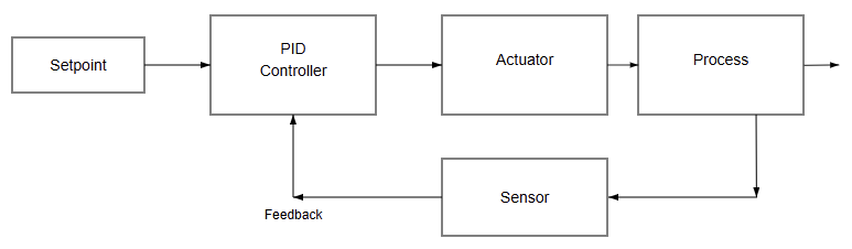
A typical PID loop consists of four main elements. These elements are the process, sensor, controller, and actuator.
The process is the physical system being controlled. Examples include a heater, motor, or tank. The sensor measures the process variable.
It converts the measurement into a usable signal. The controller receives this signal. It compares the signal with the setpoint. Based on the PID algorithm, it generates an output signal.
This signal drives the actuator. The actuator applies the necessary correction to the process. This action completes the feedback loop.
Closed-Loop Control Concept
PID control operates using closed-loop feedback principles. In a closed-loop system, the controller continuously monitors output.
It adjusts its actions accordingly. This feedback mechanism allows automatic correction of deviations.
Deviations may be caused by disturbances. They may also result from operating condition changes. As mentioned above, open-loop systems rely on command.
On the other hand, closed-loop control does not depend solely on commands. This makes it more accurate in real-world applications. It also makes the system more robust.
Setpoint and Process Variable
The setpoint is the desired value the system maintains. An example is a target temperature or speed.
The process variable is the actual measured system value. The controller continuously compares these two values.
This comparison determines the control error. Changes to the setpoint create a new error value. Disturbances affecting the process variable also create errors.
These errors prompt the controller to adjust its output. The adjustment restores system balance.
The Control Error
The control error is defined as the difference between values. The values are the setpoint and process variable.
This error is the primary input to the PID controller. When the error is large, a stronger correction is produced.
As the error decreases, the controller output is reduced. The objective of PID control is to minimize this error. This must occur quickly and smoothly. Instability must not be caused.
Proportional Control Action
The proportional component produces output proportional to the current error. A larger error results in a larger corrective action. Proportional control provides an immediate response to process changes.
Using proportional control alone often leads to steady-state error. The process variable settles close to the setpoint.
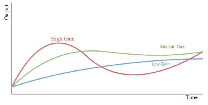
It does not settle exactly at the setpoint. The proportional gain determines controller aggressiveness. It determines reaction strength to error.
Integral Control Action
The integral component addresses limitations of proportional control. It considers accumulated error over time.
It continuously sums the error. It adjusts the controller output accordingly. This eliminates steady-state offset.
Integral action is useful when precise control is required. Excessive integral gain can lead to overshoot. It can also cause oscillations.
This occurs especially during transient conditions. Careful tuning is necessary. Accuracy and stability must be balanced.
Derivative Control Action
The derivative component predicts future behavior. It responds to the rate of change of error. It provides a damping effect to improve system stability. It also reduces overshoot.
Derivative control is useful in fast-response systems. It is also useful in oscillatory systems. Because it reacts to error changes.
It can amplify measurement noise. Proper filtering is necessary.
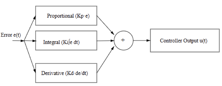
Combined PID Control Action
In a PID controller, all three actions are combined. They produce the final control output. Each component plays a specific role.
For instance, proportional control provides immediate correction. Integral control removes steady-state error.
Derivative control improves dynamic stability. When properly tuned, combined PID action delivers fast control. It also delivers accurate control.
The control remains stable. This performance applies across many operating conditions.
Mathematical Representation of PID Control
PID control is often represented mathematically. It is expressed as a sum of three terms, and the controller output equals proportional gain times error. It also includes integral gain times the integrated error.
Derivative gain multiplies the rate of error change. This mathematical model helps engineers analyze behavior. It also supports an appropriate tuning strategy design.
Controller Output and Actuators
The PID controller output drives the final control element. Examples include control valves, variable frequency drives, or heaters.
This output may be analog or digital. It may also be pulse-width modulated. This depends on system design.
Output limits are often implemented. They protect equipment and ensure safe operation. Actuator characteristics influence loop performance significantly. These include response speed and operating range.
Sensors and Measurement Accuracy
signals, Sensors and transmitters play a critical role in PID loops. They provide accurate and reliable measurements. Common industrial signals include 4–20 mA.
They also include voltage signals, which are 0–10 V. Digital communication protocols are also common.
Poor sensor accuracy can degrade control performance. Noise and delay can also cause instability. Proper sensor selection is essential. Correct installation is equally important.
Disturbances and System Stability
Disturbances are external factors affecting the process. Examples include load changes and supply variations.
Environmental influences are also common disturbances. A well-tuned PID loop compensates disturbances automatically.
This occurs through feedback. Stability refers to a system’s recovery ability. It describes a return to steady operation.
Unstable systems exhibit sustained oscillations. They may also show divergent behavior. Stable systems settle smoothly.
PID Tuning Methods
PID tuning involves selecting appropriate gain values. These include proportional, integral, and derivative gains.
Manual tuning most of the time relies on trial-and-error adjustments. These adjustments are based on observed system response.
Classical methods include the Ziegler–Nichols technique. They provide initial tuning guidelines.
These guidelines are based on oscillation behavior. Modern controllers include auto-tuning functions. These simplify commissioning. Expert verification remains important.
Digital Implementation of PID Loops
Most PID loops are implemented digitally today. They run in programmable logic controllers.
They also run in distributed control systems, and microcontrollers are also commonly used.
Digital implementation requires careful sampling time selection. This ensures accurate approximation of continuous control behavior. Poor sampling choices lead to degraded performance. They can also cause instability.
Industrial Applications of PID Loops
PID loops are used extensively in industrial automation. They regulate temperature in furnaces.
They adjust speed in motor drives. They control pressure in pipelines. They balance level in tanks.
Their versatility makes them suitable for many processes. These include simple and complex processes.
Many industrial plants operate hundreds of PID loops. Some plants operate thousands simultaneously.
Advantages and Limitations
PID control is popular because it is simple. It is also robust and well understood. It requires relatively low computational resources. It integrates easily with industrial hardware.
However, PID control may struggle with nonlinear systems. Long-time delays also present challenges.
Multivariable interactions can reduce effectiveness. Advanced control strategies may be required.
Key Takeaway: What is a PID loop?
This article depicted the fundamental principles of PID loops. It also described their structure and operation. A PID loop is a fundamental building block. It is essential within industrial control systems.
By combining proportional, integral, and derivative actions. Reliable automatic control is achieved.
This applies across a wide range of applications. Proper understanding of PID components is essential.
Behavior and tuning techniques are equally important. These ensure stable and accurate system performance.
Despite advanced control methods. PID loops remain trusted and indispensable. They remain essential in modern automation.
FAQ: What is a PID loop?
What is a PID loop?
A PID loop is a feedback control system that maintains a desired value.
What does PID stand for?
PID stands for Proportional, Integral, and Derivative.
What is the purpose of a PID controller?
Its purpose is to minimize error between setpoint and process value.
How does a PID loop work?
It continuously measures error and adjusts output automatically.
What is a setpoint in a PID loop?
The setpoint is the desired target value.
What is the process variable?
It is the actual measured value of the process.
What does the proportional term do?
It reacts proportionally to the current error.
What does the integral term do?
It eliminates steady-state error over time.
What does the derivative term do?
It predicts error changes and improves stability.
Where are PID loops commonly used?
They are used in temperature, speed, pressure, and flow control.
Why are PID loops popular?
They are simple, reliable, and effective.
Can PID loops handle disturbances?
Yes, feedback allows automatic disturbance correction.
What is PID tuning?
It is the adjustment of PID gains for best performance.
What systems implement PID control?
PLCs, DCSs, and microcontrollers commonly implement PID loops.
